 WJCarpenter
I designed a 3D printed enclosure for the D1 Mini and relay board. The design is in OpenSCAD, but it uses Willem Aandewiel's YAPPgenerator template, a handy bit of coding for making custom enclosures for electronics projects. I've used it before with great results. Even though it's intended to hold a PCB, it still works great for this project.
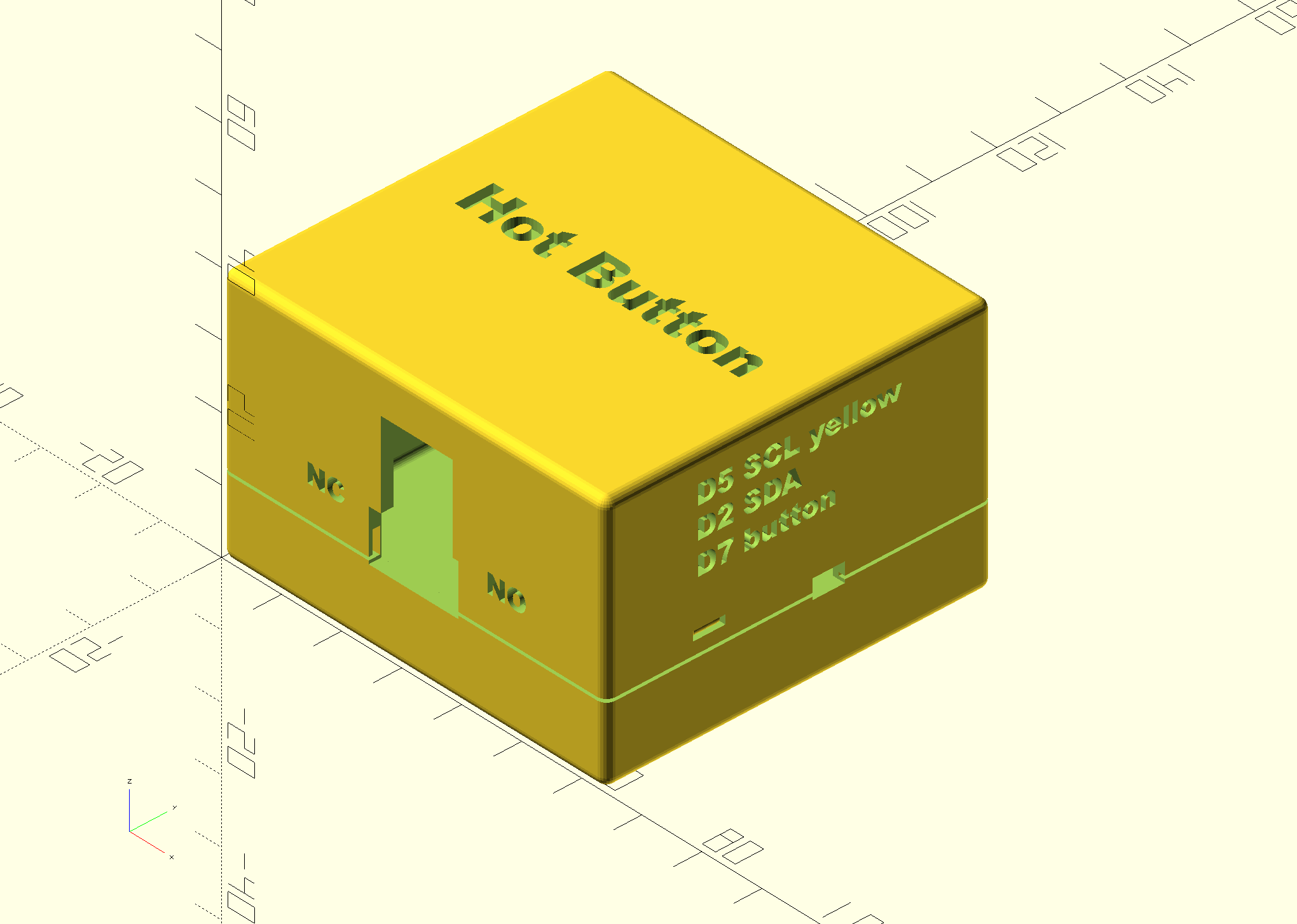
There's a lot going on with this enclosure, and it's easier to see it in the OpenSCAD rendering than in a photo of the printed box, so that's where I'm pulling the graphics from. The enclosure is in two pieces, a short "base" and a taller "lid". The two pieces are held together with three small clips around the edges and further aligned with a pin-and-post mechanism inside. I have to be honest and say I had to print this several times as I experimented to get the dimensions just right.
On the lid of the enclosure is just simple label "Hot Button". On one side is an opening for the USB power port and the contacts for the relay. The D1 Mini is above the relay board specifically because the relay board needs a wider opening, and it makes it easier to print without supports by using that orientation. The mini breadboard will be stuck with it's double-sided tape to the lid, under the "Hot Button" label.
I put some hints for myself in text on the enclosure so that I won't have to refer to notes when I am down in the basement fooling around with it. I know from past experience how easy it is to pull the wires out of the breadboard and needing to figure out the positions for plugging them back in. Near the opening for the relay contacts is a reminder of which side is normally open and which side is normally closed. On another side are reminders of which GPIO pins I used. I used the D1 Mini pin names because that's what I would be looking at when re-assembling things. I only needed to remind myself of the SCL and SDA pins for the I2C interface since the ground and power are obvious. Further, when the enclosure is closed, there is a reminder that the SCL line is using a yellow wire. Again, power and ground are obvious, and SDA must be whatever other wire is left over.
On the same side as those pin reminders is a small cut-out for the I2C wiring to connect the climate sensor. There's another cut-out like it on the opposite side because I haven't decided which side I will end up using.
On another side is a large circular cut-out for the local button switch. The 3D printer is able to print that circle on a vertical face without needing supports. Also visible is a URL to this project. That's for the benefit of some future owner of my house who might be wondering what the heck this little box is.
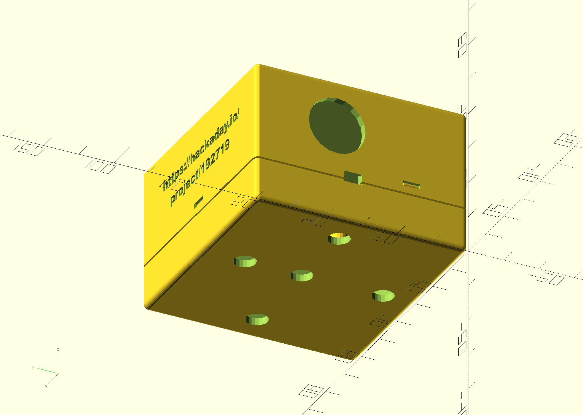
I'm not yet sure how I will mount this enclosure. I might use velcro or 3M Command Strips to stick it on the side of the water heater, or I might use screws to attach it to the wall. For that latter case, I put a few holes in the bottom of the base for screws.
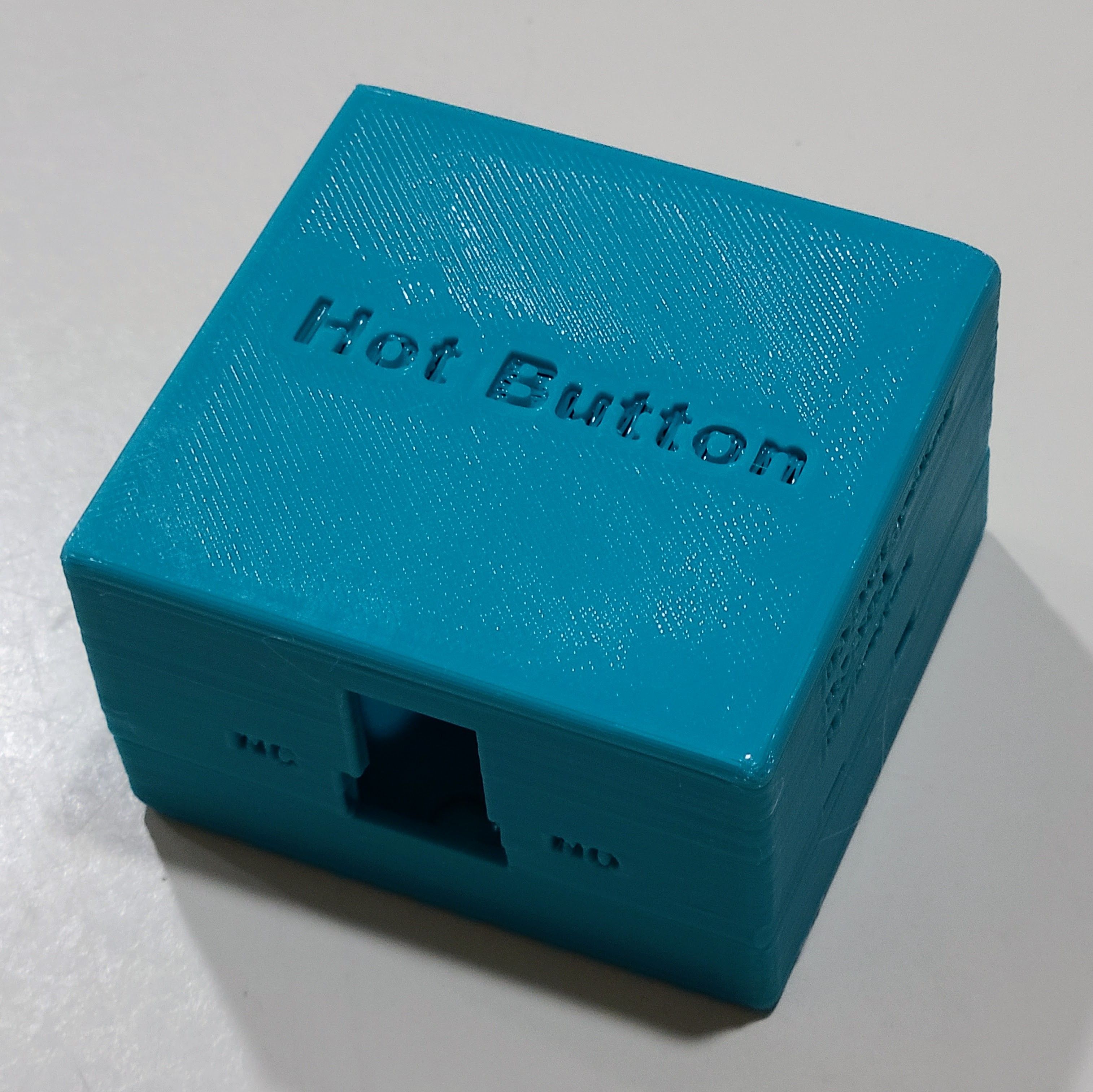
Here's the actual printed enclosure. I printed it with teal PLA+ filament with 0.28 layer thickness and 15% infill. Although PLA+ is a little bit fragile due to stiffness, I don't expect to take the thing apart very often. Since it will live in an out of the way location, it's also not worth printing it with a smaller layer height. It's more or less 60mm in length and width, and it's about 40mm tall. In addition to the padded tape on the back of the mini breadboard, I will also use some kind of thin padding inside the base so that the whole electronics assembly is held snugly inside.
Here's the OpenSCAD design file for the enclosure.
// https://hackaday.io/project/192719-calling-for-hot-water
// Enclosure for D1 Mini with relay board.

// Template from:
//-----------------------------------------------------------------------
// Yet Another Parameterized Projectbox generator
// See https://mrwheel-docs.gitbook.io/yappgenerator_en/ for
// documentation and a download pointer.
//-----------------------------------------------------------------------

// These "local" variables have to come before the "include" statement.
// The "hbrb_" numbers are sort of fundamental constants of mine.

hbrb_bottom_zsize = 14;
hbrb_lid_zsize = 22;
// Overall PCB coordinates
hbrb_pcb_size_x  = 60;
hbrb_pcb_size_y  = 56;
hbrb_pcb_thickness = 2;
hbrb_lid_plane_thickness = 2.0;
hbrb_base_plane_thickness = 2.0;

hbrb_pin_diameter = 4;
hbrb_pin_offset  =  7;
hbrb_screwhole_diameter = 6;
hbrb_screwhole_offset   = 7;

hbrb_ridge_height = 4;
hbrb_round_radius = 1.5;

hbrb_bottom_zsize_total = hbrb_bottom_zsize + hbrb_round_radius;
hbrb_lid_zsize_total = hbrb_lid_zsize + hbrb_round_radius;

hbrb_standoff_height = hbrb_bottom_zsize_total - hbrb_base_plane_thickness - hbrb_ridge_height;

hbrb_relay_width  = 15;
hbrb_relay_height = 8;
hbrb_relay_zbase = 0;

hbrb_usb_width  = 12;
hbrb_usb_height = 14;
hbrb_usb_zbase = hbrb_relay_height - 0.5;

hbrb_i2c_width  = 5;
hbrb_i2c_height = 3;
hbrb_i2c_zbase =  0;

hbrb_button_diameter = 16;

hbrb_typeface = "Arial Black:style=regular";
hbrb_text_engrave_fraction = 0.75;

include

printBaseShell      = true;
printLidShell       = true;

wallThickness       = 2.0;
basePlaneThickness  = hbrb_base_plane_thickness;
lidPlaneThickness   = hbrb_lid_plane_thickness;

// These two heights were obtained by trial and error. The cutouts on
// the sides are either exactly at the seam where the base and lid
// join, or the seam splits the cutouts and shares it between base and
// lid. That allows you to print the whole enclosure without supports.

baseWallHeight      = hbrb_bottom_zsize;
lidWallHeight       = hbrb_lid_zsize;

ridgeHeight         = hbrb_ridge_height;
ridgeSlack          = 1.5;
roundRadius         = hbrb_round_radius;

standoffHeight      = hbrb_bottom_zsize_total - hbrb_base_plane_thickness - hbrb_ridge_height - hbrb_pcb_thickness;
pinDiameter         = hbrb_pin_diameter - 0.4;  // avoid fitting too snugly
pinHoleSlack        = 0.3;
standoffDiameter    = pinDiameter + 1.5;

pcbLength           = hbrb_pcb_size_x;
pcbWidth            = hbrb_pcb_size_y;
pcbThickness        = hbrb_pcb_thickness;

// We don't need padding because we're not concerned about the corners.
paddingFront        = 0;
paddingBack         = 0;
paddingRight        = 0;
paddingLeft         = 0;

//-- D E B U G -----------------//-> Default ---------
showSideBySide      = false;     //-> true
onLidGap            = 0; //-> 3;
//shiftLid            = 1;
//hideLidWalls        = false;    //-> false
//colorLid            = "yellow";
//hideBaseWalls       = false;    //-> false
//colorBase           = "white";
//showOrientation     = true;
//showPCB             = true;
//showPCBmarkers      = true;
//showShellZero       = true;
//showCenterMarkers   = true;
//inspectX            = 0;        //-> 0=none (>0 from front, <0 from back)
//inspectY            = 0;        //-> 0=none (>0 from left, <0 from right)
//-- D E B U G ---------------------------------------


pcbStands = [
   [            hbrb_pin_offset,            hbrb_pin_offset, yappBoth, yappPin]
  ,[pcbLength - hbrb_pin_offset, pcbWidth - hbrb_pin_offset, yappBoth, yappPin]
  ,[            hbrb_pin_offset, pcbWidth - hbrb_pin_offset, yappBoth, yappPin]
  ,[pcbLength - hbrb_pin_offset,            hbrb_pin_offset, yappBoth, yappPin]
];

//left and right: parallel to X-axis
//back and front: parallel to Y-axis
//length is X, width is Y

//-- left plane   -- origin is pcb[0,0,0]
// (0) = posx
// (1) = posz
// (2) = width
// (3) = height
// (4) = angle
// (5) = { yappRectangle | yappCircle }
// (6) = { yappCenter }
cutoutsLeft =  [
   [pcbLength/2 - hbrb_usb_width/2+0.5,   hbrb_usb_zbase,   hbrb_usb_width,   hbrb_usb_height,   0, yappRectangle]
  ,[pcbLength/2 - hbrb_relay_width/2,     hbrb_relay_zbase, hbrb_relay_width, hbrb_relay_height, 0, yappRectangle]
];

//-- back plane  -- origin is pcb[0,0,0]
// (0) = posy
// (1) = posz
// (2) = width
// (3) = height
// (4) = angle
// (5) = { yappRectangle | yappCircle }
// (6) = { yappCenter }
cutoutsBack =   [
   [pcbWidth/2,     hbrb_i2c_zbase,               hbrb_i2c_width,       hbrb_i2c_height, 0, yappRectangle]
  ,[pcbWidth/2 + 7, hbrb_button_diameter/2 + 7.5, hbrb_button_diameter, 0,               0, yappCircle]
];
cutoutsFront =  [
   [pcbLength*(1/2), hbrb_i2c_zbase, hbrb_i2c_width, hbrb_i2c_height, 0, yappRectangle]
];

//-- base plane    -- origin is pcb[0,0,0]
// (0) = posx
// (1) = posy
// (2) = width
// (3) = length
// (4) = angle
// (5) = { yappRectangle | yappCircle }
// (6) = { yappCenter }
// These aren't lined up perfectly, but it doesn't matter since they will not normally be
// visible. Five holes for maximum screw mounting flexibility.
cutoutsBase = [
   [hbrb_screwhole_offset, pcbLength/2, hbrb_screwhole_diameter, 0, 0, yappCircle]
  ,[pcbLength - hbrb_screwhole_offset, pcbLength/2, hbrb_screwhole_diameter, 0, 0, yappCircle]
  ,[pcbWidth/2, hbrb_screwhole_offset, hbrb_screwhole_diameter, 0, 0, yappCircle]
  ,[pcbWidth/2, pcbLength-2*hbrb_screwhole_offset, hbrb_screwhole_diameter, 0, 0, yappCircle]
  ,[pcbWidth/2, pcbLength/2, hbrb_screwhole_diameter, 0, 0, yappCircle]
];

// Little tabs for holding the two halves of the case together.
snapJoins   =   [
   [pcbLength/2 ,   4, yappRight]
  ,[pcbWidth*(1/4), 4, yappFront]
  ,[pcbWidth*(1/4), 4, yappBack]
];

//-- origin of labels is box [0,0,0]
// (0) = posx
// (1) = posy/z
// (2) = orientation
// (3) = depth
// (4) = plane {lid | base | left | right | front | back }
// (5) = font
// (6) = size
// (7) = "label text"
// trial and error positions since no way to calculate rendered sizes in OpenSCAD, and YAPP is always left-justified
labelsPlane =  [
   [ 8,  pcbLength/2 - 2,      0, lidPlaneThickness * hbrb_text_engrave_fraction, "lid",  hbrb_typeface, 6, "Hot Button" ]

  ,[14,  roundRadius+16,  0, lidPlaneThickness * hbrb_text_engrave_fraction, "left",  hbrb_typeface, 3, "NC" ]
  ,[44,  roundRadius+16,  0, lidPlaneThickness * hbrb_text_engrave_fraction, "left",  hbrb_typeface, 3, "NO" ]

  ,[14,  hbrb_bottom_zsize+hbrb_lid_zsize - 4,  0, lidPlaneThickness * hbrb_text_engrave_fraction, "front",  hbrb_typeface, 3, "D5 SCL yellow" ]
  ,[14,  hbrb_bottom_zsize+hbrb_lid_zsize - 8,  0, lidPlaneThickness * hbrb_text_engrave_fraction, "front",  hbrb_typeface, 3, "D2 SDA" ]
  ,[14,  hbrb_bottom_zsize+hbrb_lid_zsize -13,  0, lidPlaneThickness * hbrb_text_engrave_fraction, "front",  hbrb_typeface, 3, "D7 button" ]

  ,[12,  roundRadius+26,  0, lidPlaneThickness * hbrb_text_engrave_fraction, "right",  hbrb_typeface, 3, "https://hackaday.io/" ]
  ,[16,  roundRadius+20,  0, lidPlaneThickness * hbrb_text_engrave_fraction, "right",  hbrb_typeface, 3, "project/192719" ]

// if you are changing things and lose track of which side is which, you can uncomment these temporarily
//, [ 8,   5,   0, 1, "left",  hbrb_typeface, 7, "L" ]
//, [40,   5,   0, 1, "front", hbrb_typeface, 7, "F" ]
//, [5,    5,   0, 1, "back",  hbrb_typeface, 7, "B" ]

];

//---- This is where the magic happens ----
YAPPgenerate();
Discussions
Become a Hackaday.io Member
Create an account to leave a comment. Already have an account? Log In.