 JP Gleyzes
What is it ?
End of August, my brother designed a small PCB to accomodate the excellent project OpenXsensor on Raspberry Zero.
Mstrens published a very versatile solution to use this cheap but powerful MCU to get a multiProtocol solution for telemetry.
Here is how this project can be used to build an inexpensive PCB to add the following sensors to your FS-IA6B receiver. (could be easily adapted to other receivers).
- a variometer
- a battery voltage sensor
- a GPS tracker
- an optionnal current sensor
- 1 to 4 extra channels added to your 6 channels FS-IA6B
The final device looks more or less like a cube 28 mm x 30 mm x 18 mm
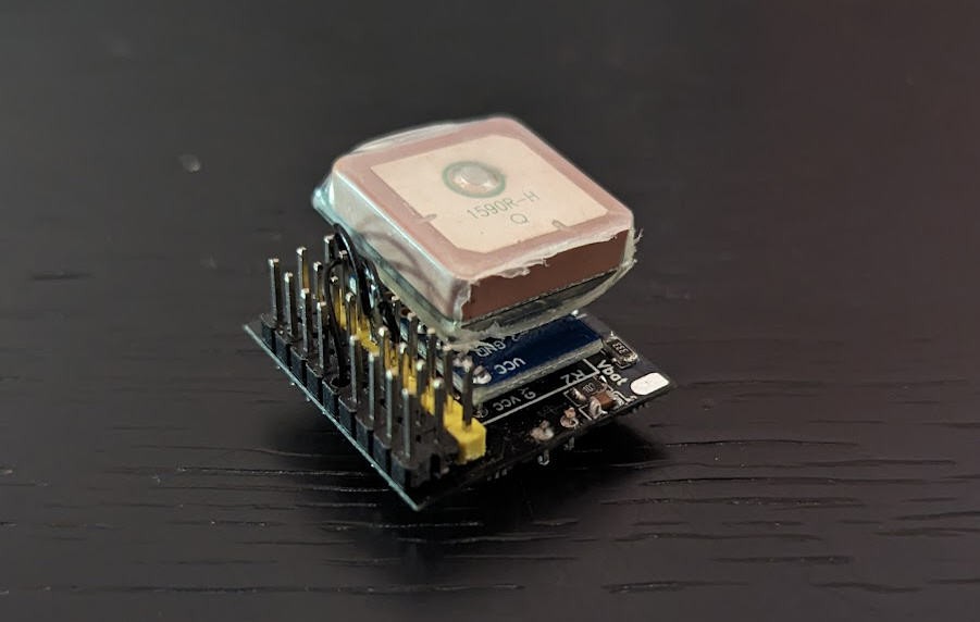
It could even be smaller with newest generations of GPS modules.
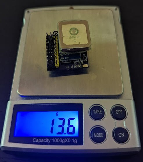
And it weights less than 14g
Optionnally (for french pilots) we will see how to modify a TX16s radio to incorporate a "remoteID" beacon in it.
This will be compliant with french regulations for drone identification.
Follow this project and you will be able to build yours, configure it and fly !
It is not exactly a new design, but rather an "integration project" of existing solutions. So credits will go to people who produced these open source solutions. They will be quoted in time!
Schematics
Schematics for this project cannot be simpler... it's basically just an integration of existing DIY modules !
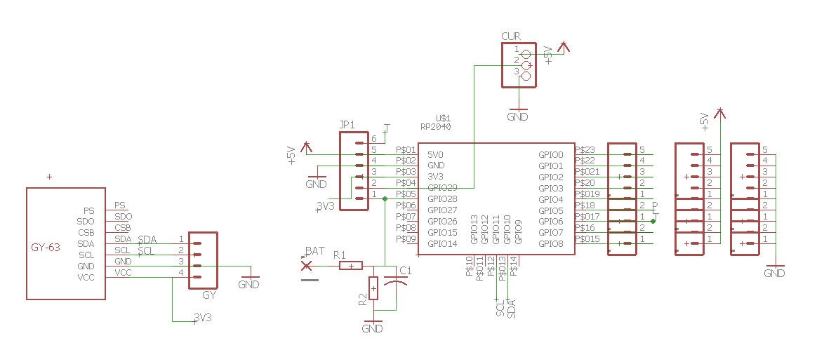
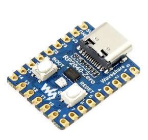
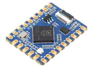
The heart is a Raspberry zero :
It could also be a raspberry tiny which is pin to pin compatible but doesn't have the USB connector.
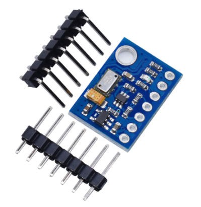
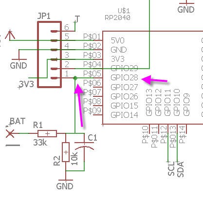
A GY-63 pressure sensor MS5611 is connected to the I2C port
Then a voltage divider is added to measure battery voltage.
- For lipo 3s pack R1 = 33k R2 = 10k
- For lipo 4s pack R1 = 47k R2 = 10k
And finally a few connectors are also added to connect sbus, Ibus and to allow extra channels to be accessible.
Power of the RP2040 is provided by these connectors. 5V is coming from the SBUS connector of the receiver which is itself connected to the 3 pins marked "T" (for Telemetry) obn the board.
PCB
Aeropic routed this schematics to design of PCB. It's a very compact "mezzanine style" PCB
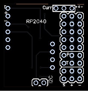
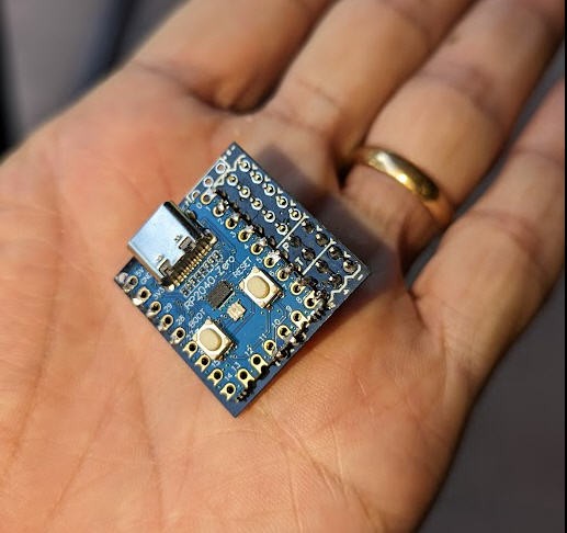
When assembled (without the GPS) it looks like this
The PCB was sponsored by PCBWay and you can order it on their site into my "shared projects"
Soldering is not totally simple as the GY-63 must be soldered first and the pin headers supporting it shouldn't protude too much on the other side where the RP2040 is soldered!
This video gives a step by step process for soldering the board but also for configuring it
Firmware
We will install OpenXsensor on this little board.
Mstrens made a fantastic job to allow OpenXsensor to run on Raspberry Zero boards. His project on github worths to spend a few hours reading : openXsensor (oXs) on RP2040 board
It could be a little intimidating at first glance. But here are the simplified steps to run your board with this firmware:
install the firmware
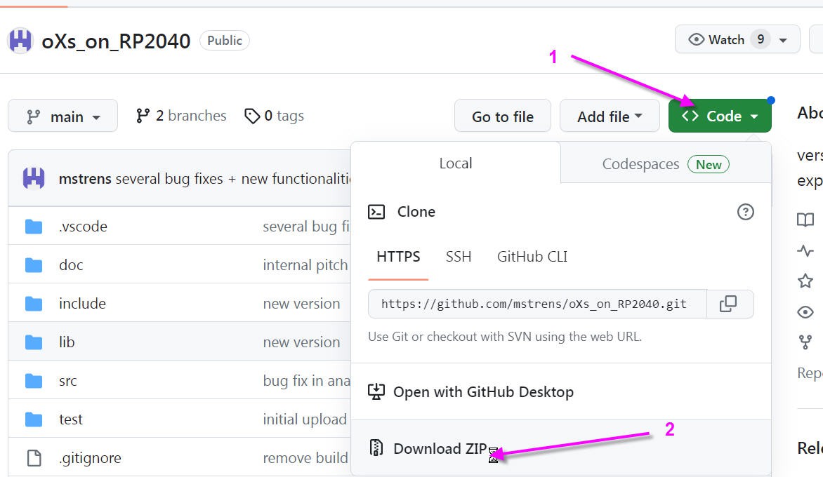
- download all the project from github
- click on "code" button
- then download zip
unzip all the file and open it until you see these files
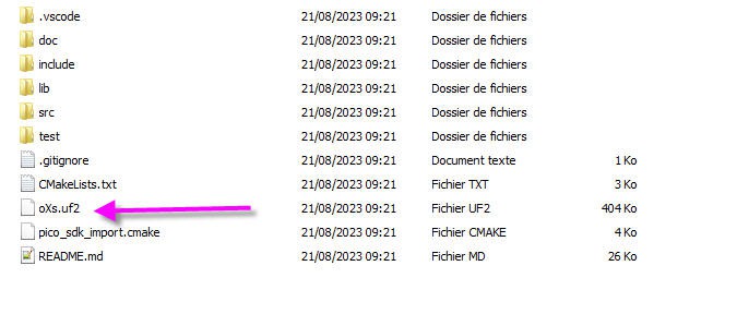
the oXs.uf2 is the binary firmware that you will have to flash into your RP2040
To do this, simply press the boot button on the RP2040 board and (while pressing) connect the board to your PC USB plug. Release the boot button and you should see a new USB disk poping up : this is the bootlader disk.
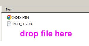
Simply drag and drop the oXs.uf2 file into this disk and your fimware will upload automatically!
When done you should see the red led flashing. OpenXsensor is running!
Configuring OpenXsensor
OpenXsensor is a very open firmware; it can work with custom boards (like ours) so you have to tell him which pin is used and for which kind of sensor!
This can be done using a serial terminal connected to the USB port of your RP2040.
It can be on a PC (arduino IDE serial port) or even on a smartphone.
I will show you this method as it is very handy to reconfigure things when you are into the fields!
As I am using an android phone, I downloaded Serial USB Terminal.
- download it, open it
- connect the link
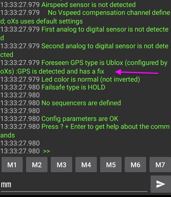
- type mm into the bottom box and return
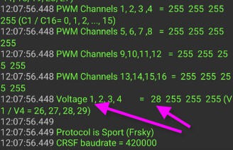
You should see this kind of screen with all the configuration displayed
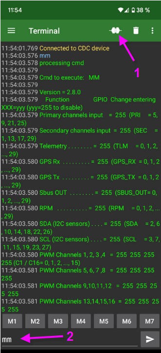
As you see all the pins are unmapped (they are at "255" value).
type one after one these commands into the serial line and press return for each command. The board will reboot, reset the connection but keep your entered configuration.
- V1 = 28
- V2 = 29
- SDA = 10
- SCL = 11
- PRI = 5
- TLM = 6 Protocol = i
Let's take the example of the first command : V1 = 28
It simply tells the firmware that Voltage 1 of the telemetry will be affected to pin 28 of the board. And pin 28 is the ADC where is connected the battery voltage divider !
So type this into the command line,
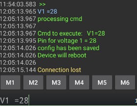
reconnect the link and type mm, and will see that the pin28 is affected to V1
Ok : simple ?
Now do the same with the other commands :
- V1 = 28
- V2 = 29
- SDA = 10
- SCL = 11
- PRI = 5
- TLM = 6
- Protocol = i
- V2 is for optionnal current sensor
- SDA and SCL are to configure the GY-63 board
- PRI will tell the board that the pin5 can be used as a "Primary Channel" (Pin marked P on the board)
- TLM tells the board that the Telemetry will be output on pin 6 (pin marked T on the board)
- Protocol will tell the board that our receiver is compatible with Ibus
Your board is now configured and should be connected to your receiver (we will see this later)
Adding a GPS tracker
You can connect GPS devices on OpenXsensor. If you have a Ublox model then configuration will be damn simple.
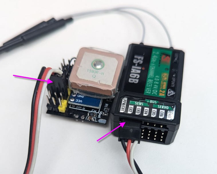
Solder a connector or the wires to pins :
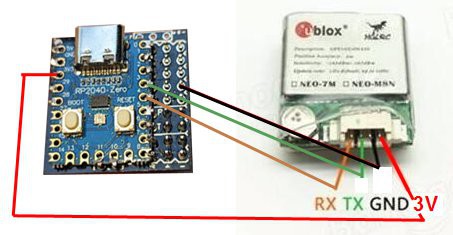
Note that I power the GPS with 3.3V coming from voltage regulator of the RP2040. This is to avoid GPS_TX pin to output 5V signals...
now you can configure again your board by typing the following commands:
- GPS_RX = 4
- GPS_TX = 3
And that's it your GPS is connected and the board recognizes it:
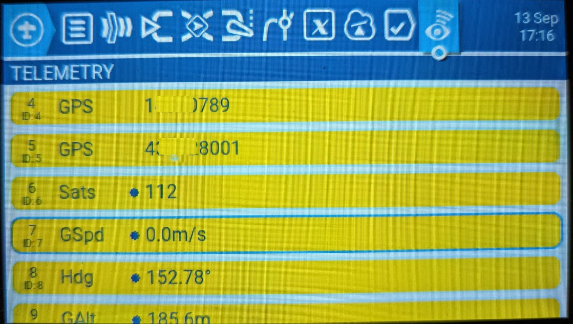
If you want to see the values of the fix then type the FV command:
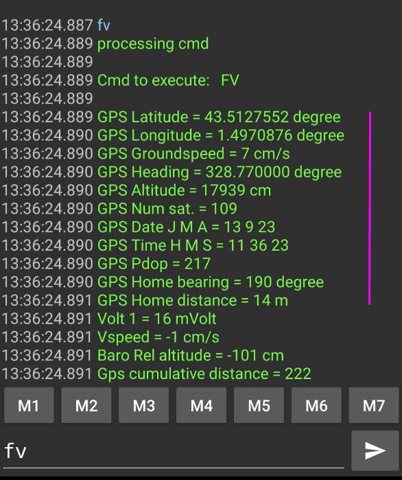
This command will display all the sensors values captured by the firmware. GPS (pink line) then GY-63 board converted to altitude and variometer values. And the V1 voltage (not connected to battery for this exemple).
Your board is finished and works. Now we will try to use it !
Using the board with TX16s radio and FlySky FS-IA6B receiver
Connection
Start by connecting the T plug of the board to the SENS Ibus connector of the FS-IA6B (telemetry port).
Do this with a regular servo wire with 3 pins female headers.
Discover telemetry on TX16s radio
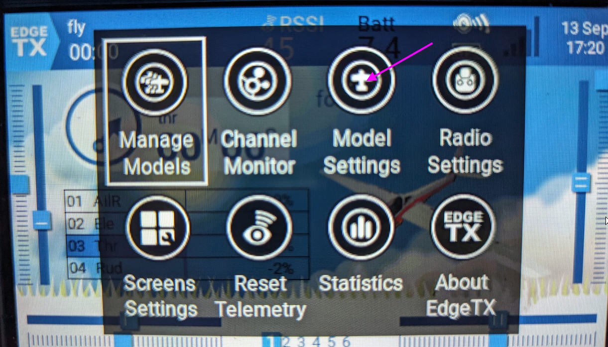
Power the receiver as usual, then on your model go to the "model settings" menu and click on the telemetry page
Then click on "discover new" button
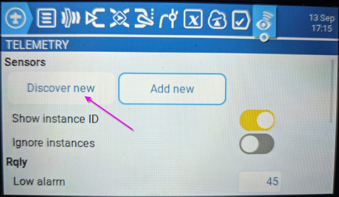
And you will get all the discovered sensors of your board !
As you can see the GPS data are longitude and latitude in decimal degrees but with values multiplied by 10000000... And they do have the same name "GPS" for lon and lat. We have to change their name.
It was a bug fixed in release V2.9.1 of EdgeTx.
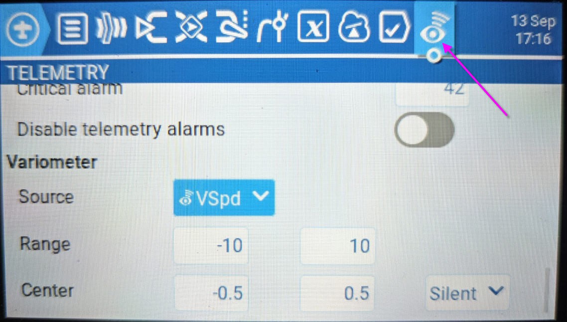
configure the variometer
While you are on the telemetry page you can configure your variometer. Scroll down to the bottom of the page
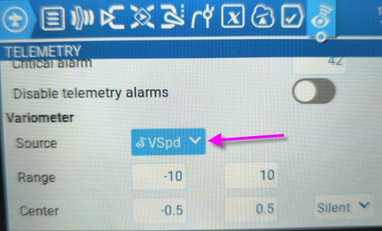
Be sure to select the VSpd (vertical Speed telemetry) as the source, then you can select the dead band you want to avoid beeps when almost no vertical motion.
And now if you move up/down your board you should ear the variometer beeps/beeps !
A black box in your model
In case of a crash it could be very useful to have a "black box" to know where is the last known position of your plane before (or after) crash.
EdgeTx offers this possibility and you can of course select the parameters to store in the black box. Again have a look at the telemetry page and tick the box "log"
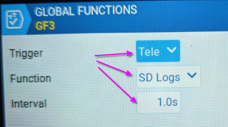
They call this feature "logs". You can enable logging via a "global function"
Go to the system menu (press SYS key)
then select the global functions tab and insert a new GF (already done on this picture)
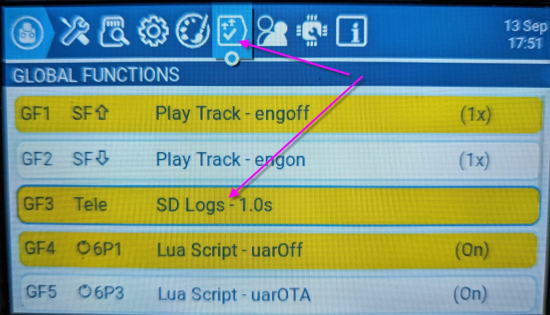
this function should be triggered when telemetry (tele) is received and will output data to the SD card logs every 1s.
Access the logs
Now any time you power your receiver it will transmit telemetry. This telemetry will be logged into your SD card in the folder named "logs". Logging will stop after flight or when changing model.
So you just have to connect a USB cable to your PC or your phone and search for this folder
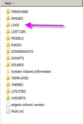
Open it and search the log of your last flight. It's a .csv file containing all the sensors, the sticks, the buttons etc...
Look for the lon and lat columns, pick up the lon and lat values and you can search your plane using google maps !
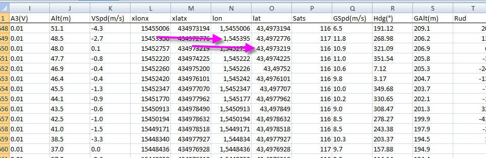
You can even use online converters to read this excel file and convert it into kml file.
Mygeodata works really well.
This could conclude this project as everything is working.
You have a telemetry addon for your receiver, capability of adding a variometer and a GPS tracker for your plane !
But I wanted to go even further and use these GPS data to integrate a "remoteID" beacon into my radio.
The DroneID beacon ("remoteID" for french pilots)
USA have now a legal text enforcing the use of a beacon identification for UAVS. In France we do have more or less the same law (but with a different specification).
The idea here is to implement a ground based "DroneID" beacon emitting the frames required by french law to identify a flying drone and its pilot.
So this implementation will NOT comply with US laws... but ONLY with French law.
Here is what says (after google translation) the french legal text
The transmission of data mentioned in article R. 20-29-2 of the postal and electronic communications code has the following characteristics:
1° The reporting message consists of a single WiFi frame;
2° The reporting message is not encrypted;
3° The reference of the geodetic system is EPSG 4326. The coordinates are transmitted in “degrees/decimals of degrees”:

- the transmitted latitudes are included in the interval [- 90°; + 90°]
- the longitudes transmitted are included in the interval]- 180° (excluded); + 180° (inclusive)].

4° The route transmitted, the true route, takes the geographic north as a reference;
5° The data is transmitted in units respecting the International System:

- speed in meters per second,
- vertical position in meters.

6° The transmission coding system is UTF-8;
7° The data is transmitted using the TLV (Type Length Value) mechanism and corresponds to the types defined in the table of types attached to this order.
8° The time base is UTC+00/00;
9° The transmission of the reporting message is carried out from the take-off of the aircraft traveling without anyone on board until its landing and periodically according to one or other of the following two processes :

- either on any WiFi channel in the 2400 to 2483.5 MHz band and in accordance with the beacon frame transmission standard as defined by the IEEE 802.11 (100 TU) standard, on the condition that the signaling system is native to the aircraft traveling without anyone on board and is coordinated with the latter's command and control system;
- either on Wifi channel number 6 at the first of the following temporal or spatial terms:
- 2 sendings are separated by at most 3 seconds;
- 2 shipments are separated by at most 30 meters.
By chance an open source implementation of these specifications has been done by Pierre Khancyr. He wrote an arduino library compatible with ESP32 hardware. DroneID_FR, code source on his github page.
He wrote also an implementation of this library on a TTgo ESP32 board: TTgo_T_Beam project
So all the credits for DroneID must go to Pierre and his valuable work.
What I did is simply to modify the TTgo_T_Beam project to interface it with the telemetry coming from TX16S radio.
In a few words :
- GPS data needed to comply with french DroneID come from the RP2040 board via telemetry
- these data are sent via the TX16s serial port to an ESP32 board hidden into the radio
- this ESP32 uses its wifi and DroneID_FR library to emit drone identification frames
Source code for the ESP32 beacon.
The code is available on my github page here : DroneID_fr_telemetry
Compared to Khancyr's code, I simply added a JSON serial interface with the telemetry received by TX16s radio.
Format of the JSON message is
{
"OTA":0,
"lat":433828245,
"lon":13870095,
"GSpd":0,
"Hdg":193.33999633789,
"GAlt":183.60000610352
}
Meaning that values needed to comply with the french DroneID can be easily found into these messages.
Afterwhat the original DroneID_fr library is used to broacast the frames.
Nothing complex! Excepted the work done by Pierre Khancyr ...
As this ESP32 board will be hidden into the TX16s radio, and thus not physically accessible for uploading new firmware, I have added the possibility to upload firmware Over The Air. This is done using the OTA mode of ESP32, and is triggered via the same JSON message with the boolean "OTA". If OTA == 1 then the droneID beacon is stopped and replaced by a connection to your wifi router to allow OTA.
Hardware inside the TX16s radio
To connect our ESP32 to the radio we will use its serial ports. They are acessible from outside the radio. I choosed AUX2 port.
Connection will be like this
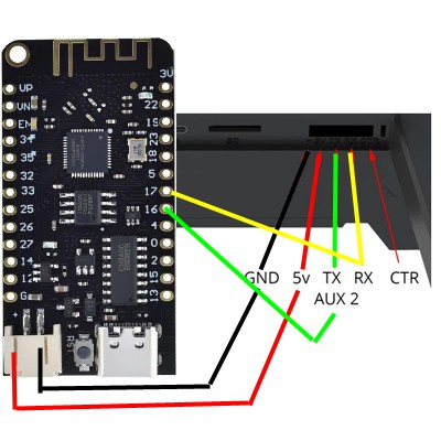
Note that only the TX pin is important (and of course 5V and ground).
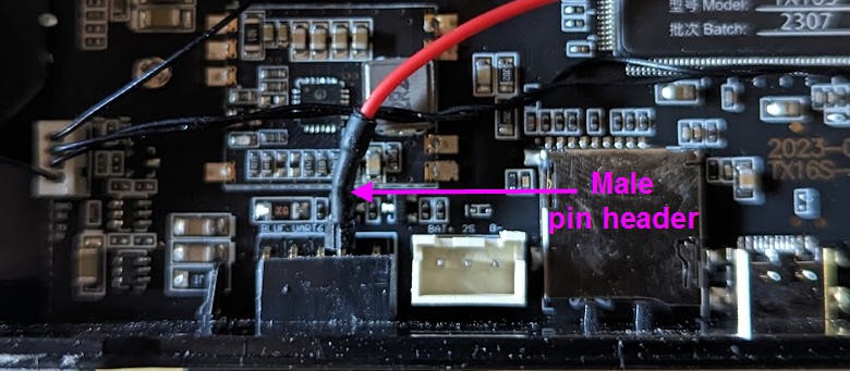
Rather than having the ESP32 outside the radio I prefered an internal integration. So I opened my TX16s and discovered a free connector on the left sde of the PCB with AUX2 pins exposed:
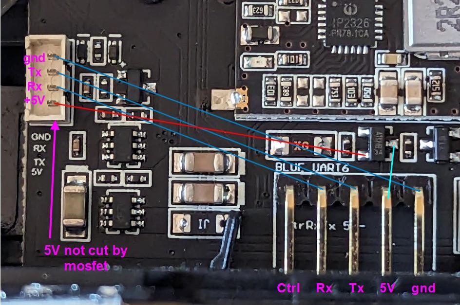
However I discovered that the 5V pin of this connector is not cut by the mosfet as it is the case with the big connector...
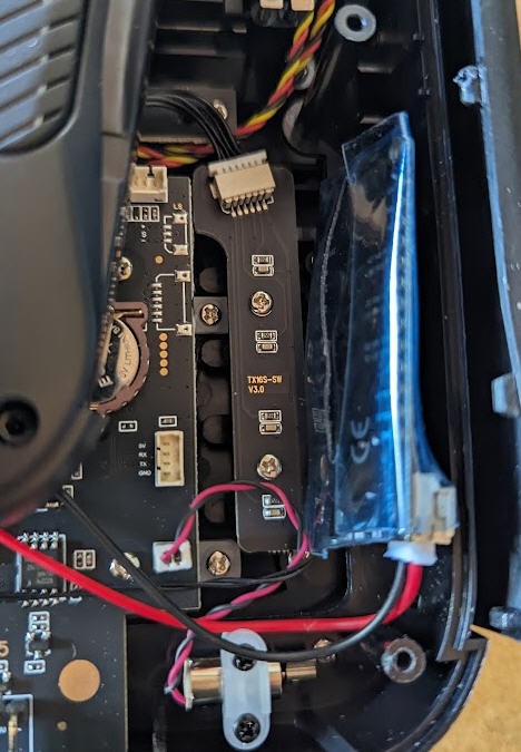
As I wanted to be able to electrically switch off the ESP32 when not in use, I adopted an hybrid solution:
- GND, Rx and Tx pins are those from the left tiny connector
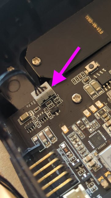
- 5V is the one from the big pin header... I managed a way not to solder on it using a pin header plastic case as a spring while inserting the metal pin from the internal side.
And that's it to be able to hide an ESP lolin32 lite board into the radio !
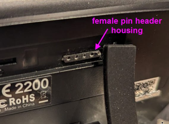
drop the ESP32 on the right side of the radio. over will close and keep the board in place.
Switching ESP32 power on and off via the TX16s radio
We will now use lua scripts to trigger all we need into the ESP32 firmware!
Let's start by powering on and off the serial2 port 5V pin.
here is the script to switch on
local function run()
  -- Called periodically while the Special Function switch is on
  -- switch on serial port 2 : serialSetPower(port_nr, value)
    serialSetPower(1, 1)
end

return { run=run }
and to switch off would be the same with 0 instead of 1 !
local function run()
  -- Called periodically while the Special Function switch is on
  -- switch off serial port 2 : serialSetPower(port_nr, value)
    serialSetPower(1, 0)
end

return { run=run }
Scripts are located into the SCRIPTS/FUNCTIONS directory of the SD card
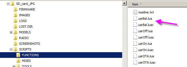
Beware that scripts names must remain very short (6 characters)
Beware also that variables declared into a script can be used by another one...
FUNCTIONS script can be trigerred by physical switches of the radio.
I have associated uarOff.lua script to FM0 mode button of the radio. So that when FM0 button is pressed the AUX2 5V pin is not powered (0V) and the ESP32 will shut down totally
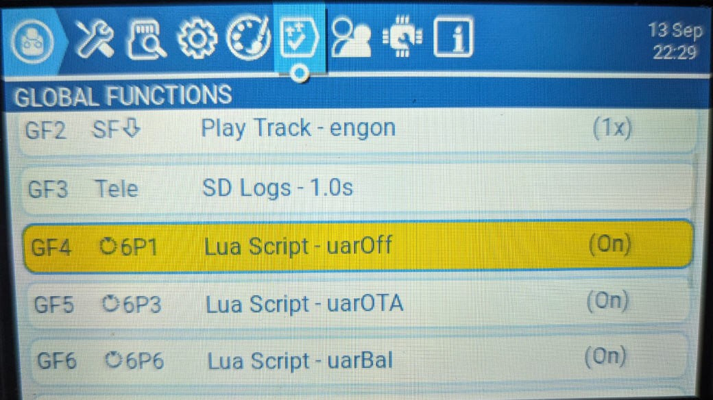
toggle modes with TX16s radio : ESP32 off / beacon On / OTA on
You got the idea !
- FM0 will switch off the ESP32
- FM6 will start to power it and launch the DroneID beacon
- FM3 will start to power it, stop the beacon and launch the OTA mode for ESP32
As I wanted a "complex" behavior with FMx buttons I couldn't use a single script to toggle on or off the AUX2. Indeed using the "background" function of lua scripts (triggered when a button is off) would have switched off the port while another button could have switched it on... A mess
That is the reason why 3 scripts does exist
- uarOff. lua (previously explained
- uar.Bal.lua launching the beacon
local function init()
  -- Called once when the script is loaded
	mGPS =  getFieldInfo("GPS").id    -- id of the field "GPS". GPS is a "table" with GPS.lat and GPS.lon
	mGSpd =  getFieldInfo("GSpd").id  -- id of the field "GSpd"
	mHdg =  getFieldInfo("Hdg").id    -- id of the field "Hdg"
	mGAlt =  getFieldInfo("GAlt").id  -- id of the field "GAlt"
end

local function run()
  -- Called periodically while the Special Function switch is on
--{"OTA":0, "lat":43.5128245, "lon":1.4970095, "GSpd":0, "Hdg":193.33999633789, "GAlt":183.60000610352}
	serialSetPower(1, 1) -- setPower port AUX2 on --> serialSetPower(port_nr, value)
    serialWrite('{"OTA": 0, "lat":'..(getValue(mGPS).lat)..', "lon":'..(getValue(mGPS).lon)..', "GSpd":'..getValue(mGSpd)..', "Hdg":'..getValue(mHdg)..', "GAlt":'..getValue(mGAlt)..'}\n')
end


local function background()
  -- Called periodically while the Special Function switch is off
end

return { run=run, background=background, init=init }
The init function is called once the script is stored into memory during model selection.
As you can see init function will get the Id number of the named variables . This mechanism is much faster than retrieving the values of the variables by their names. It is explained into the documentation of EdgeTx_Lua optimization tricks
Then, when the button FM6 is on, the run function will execute in loop and write the telemetry values into a JSON message for the serial port AUX2 and thus for the ESP32
- uarOTA/lua will switch the ESP32 into OTA mode
local function init()
  -- Called once when the script is loaded
end

local function run()
  -- Called periodically while the Special Function switch is on
--{"OTA":1}
    serialSetPower(1, 1)
    serialWrite('{"OTA": 1}\n')
end


local function background()
  -- Called periodically while the Special Function switch is off
end

return { run=run, background=background, init=init }
Your DroneID_fr_telemetry beacon is finished and should work.
You can verify this using an external ESP32 to decode the beacon's frames. Follow this github project to use this feature : https://github.com/dev-fred/Decode_balise_ESP32
Your beacon MUST be registered on the french Alphatango platform. The procedure is quite simple and is explained into this log
Licenses
Unless otherwise stated, all works presented here that are not based on software/code are subject to the Creative Common Attribution license .
The complete legal text can be found here
Unless otherwise stated, all software/code-based works presented here are subject to the GNU General Public License v3.0
The complete legal text can be found here