 kelvinA
[9 Sep 2023]
The actual changes that I've implements aren't that numerous -- I plan to use a 2.0" transflective LCD positioned closer to the north edge, the Thumb Tetrinsic has been moved north to be the same disance from the edge as the left/rightmost Finger Tetrinsics and the height of Tetrescent is down from 44mm to 40mm -- but I've learned some things about my printer settings when trying to print out the printable concept.
Transflective LCD
I was able to find the KD020QVRMA002, a 2.0" 240x320px transflective LCD:
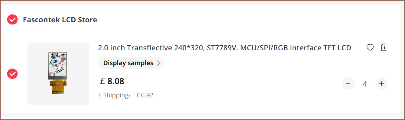
I can't find any concrete numbers, but believe it would be less reflective than the 2.7" reflective LCD. There's also 80 less vertical pixels, but I do get multiple colours and a backlight for low-light use. It also allows Tetrescent to be thinner, assuming that there's nothing else contributing to the overall thickness.
It seems that transflective LCDs come in more sizes and at lower costs than rLCDs, especially ones with frontligting.
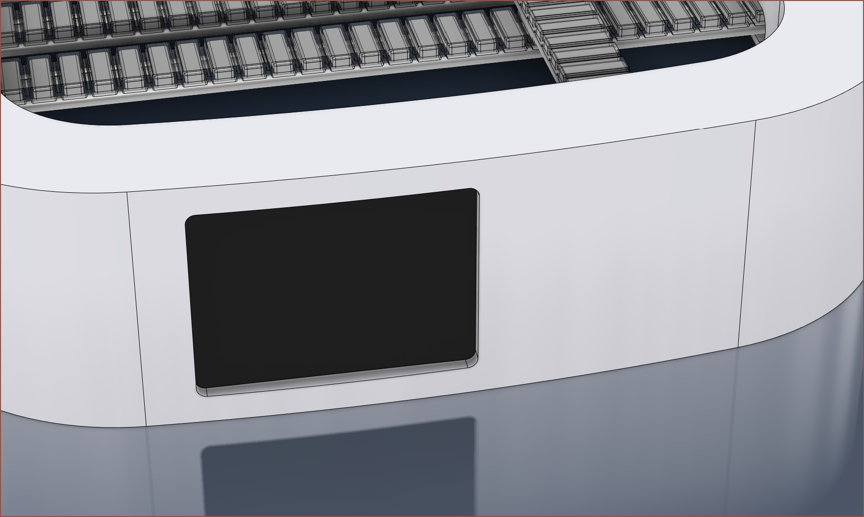
It's been placed like so to allow space for the Thumb Tetrinsic as well as it being a slightly less steep angle to see by a user. My only concern is that the square 240x240px area I plan to dedicate for the word processing interface is probably going to be the size of a 1.54" smartwatch (which I have typed on with the use of a folding keyboard just fine). It likely just means only a few words would be visible at any one time. The bottom 240x120px is dedicated to the UI concept I made for Tetent Concept3.
Printing the concept
The first attemt failed somewhat mysteriously, but I think it had something to do with some peeling-up top layers. My roughly-tuned supports were removeable, but they didn't break off as easily as I'd like, nor provide a nice looking under-layer.
For the peeling top layers, I had enabled Skin Edge Support, but I don't think the 6 layers was enough for it to stabilise. Instead of a fixed layer count, I opted to set "Skin Edge Support Thickness" to 10mm.
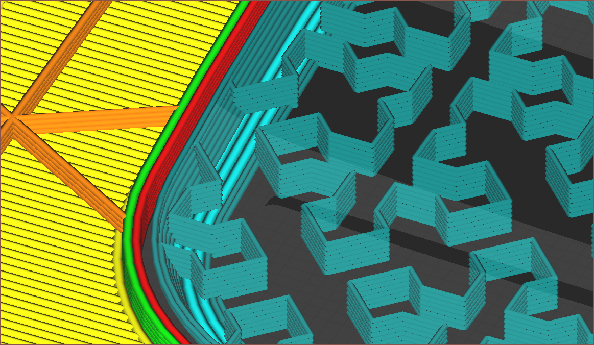
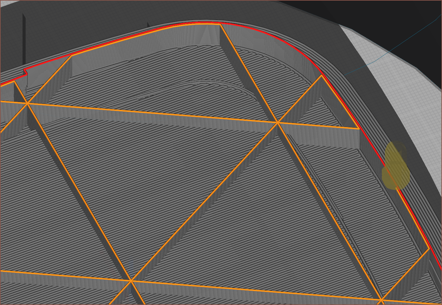
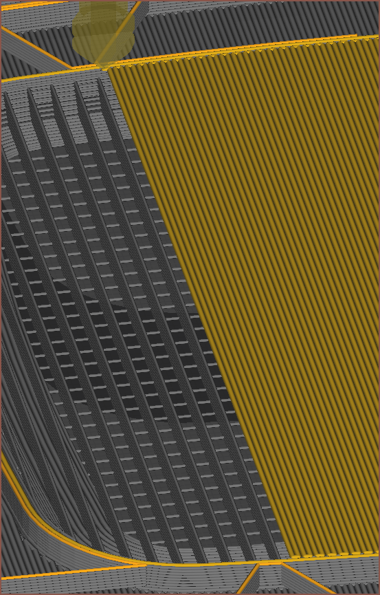
Tackling the supports, I did some researching and changed my support line width to 3/4ths of the nozzle diameter. Then I looked into support pattens and liked the look of "Cross":
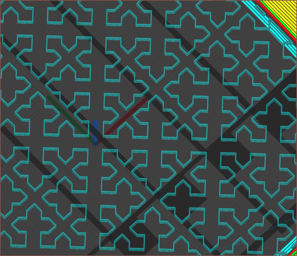
It looked like it would be a springy support structure that would break off easier. The only issue was that there seemed to be some small extrusions on the right edges, so I added a single wall via "Support Wall Line Count":
I also found out about "Enable Conical Support", which slopes the edges. This is good, since it means that the support isn't right next to the inner walls all around.
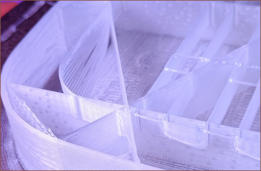
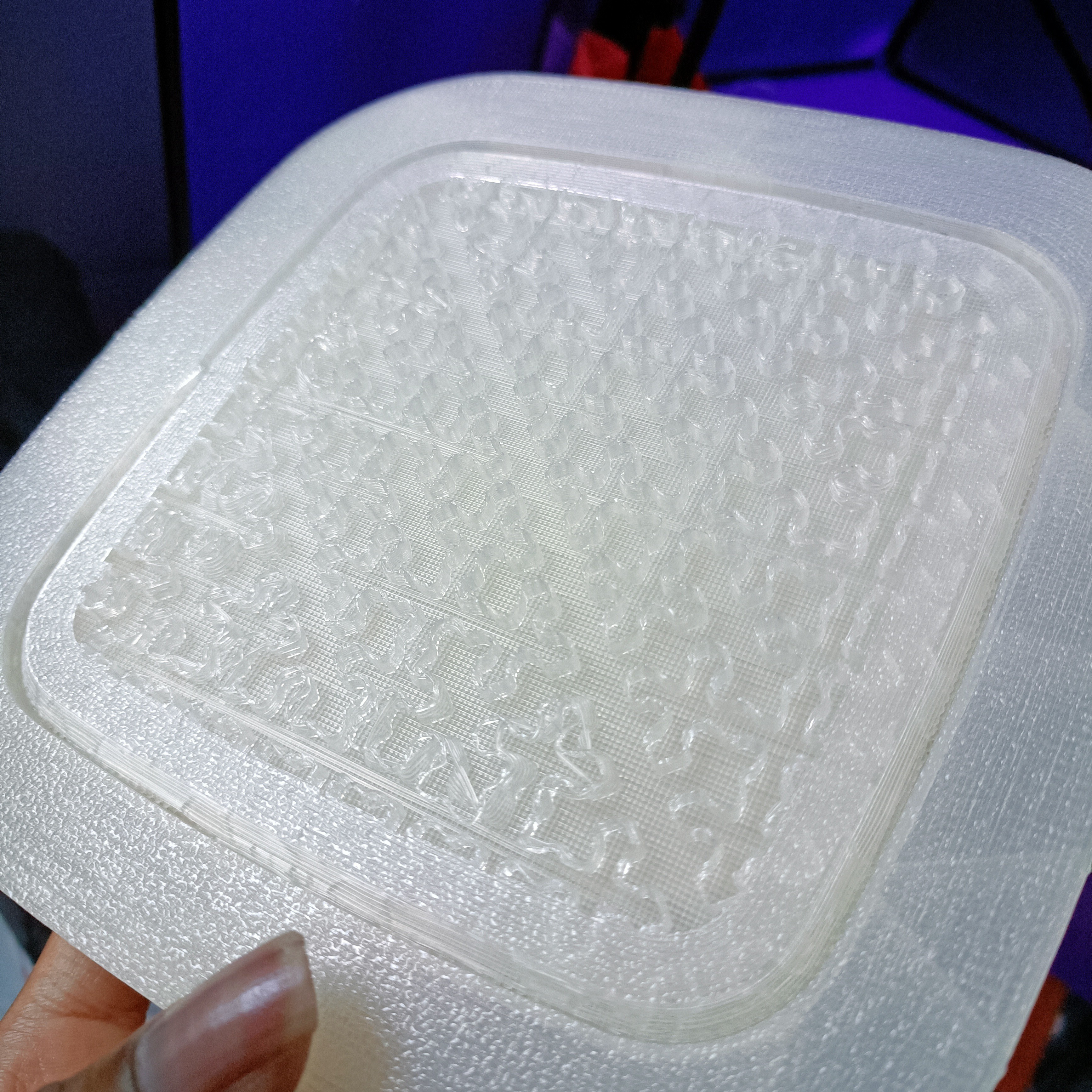
The subsequent print actually succeeded this time, and it does seem that the increased skin edge support helped. This is what it looked like when it was printing:
Trying the concept
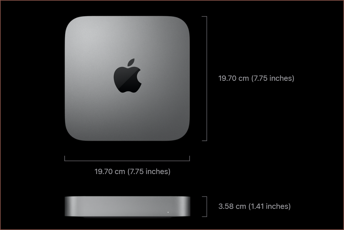
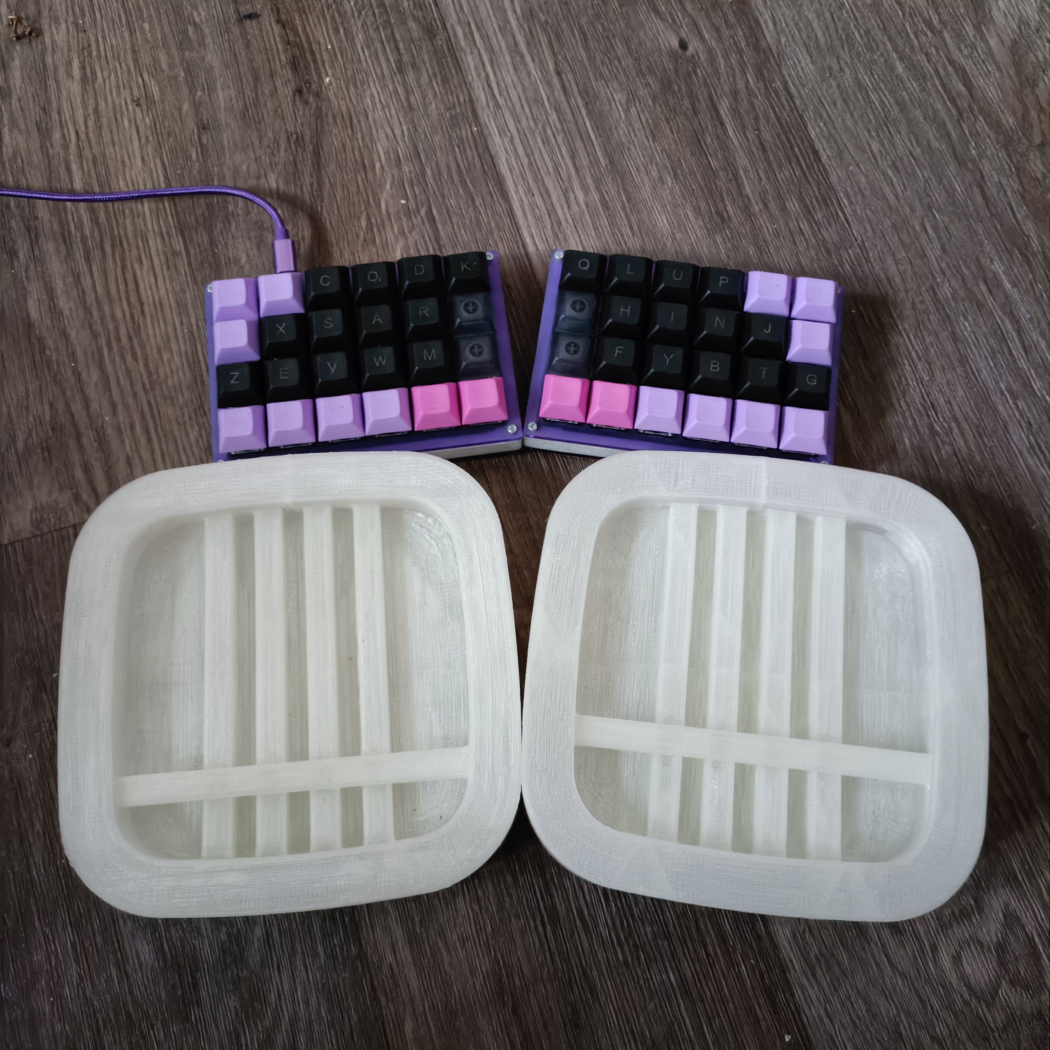
The first thing I noticed was that it's quite large in comparison to my keyboard / mouse. I can still hold it on one hand fine though, but it's more the size of a mini-pc. It's smaller in XY than a Mac Mini though.
So I sat on some stairs and I also tried it outside to see how it fares, since desks don't grow outside. Suprisingly, I think I can get it to work by getting my palm to push Tetrescent into my lap, holding it in place. When outside, sitting on railings or the floor, I was eating a sandwich in my other hand to get some real-world, single hand experience.
The only thing I thought needed changing was that the thumb was too close to the south edge. Thus, I've moved the Thumb Tetrinsic northwards:
Printing the next concept attempt
I wanted to reduce the amount of material needed to print the next concept, as well as increase print reliability. I changed my top/bottom pattern from "Lines" to "Zigzag" and reduced its speed from 60 to 54mm/s and reduced acceleration to 300mm/s/s. To counter this speed decrease, I increased my bridge speed from 30 to 45mm/s and reduced the "Bridge Skin Density" to 90%.
I also wanted to go down from 2 to 1 outer shell wall, but past experience (quite a few years ago now) suggested that wasn't a reliable idea. I thought I'd go with a "1.5" thickness by enabling "Connect Infil Polygons":
This also means that the skin support is made up of 2 or 3 lines instead of just one. I predicted that this would allow these lines to stabilise faster and reduced the thickness to 8mm.
So I sent that to print and the first thing was that the first layer was changing direction too fast and causing the supports to peel up in a few places, so I also reduced the initial layer acceleration to 300mm/s/s.
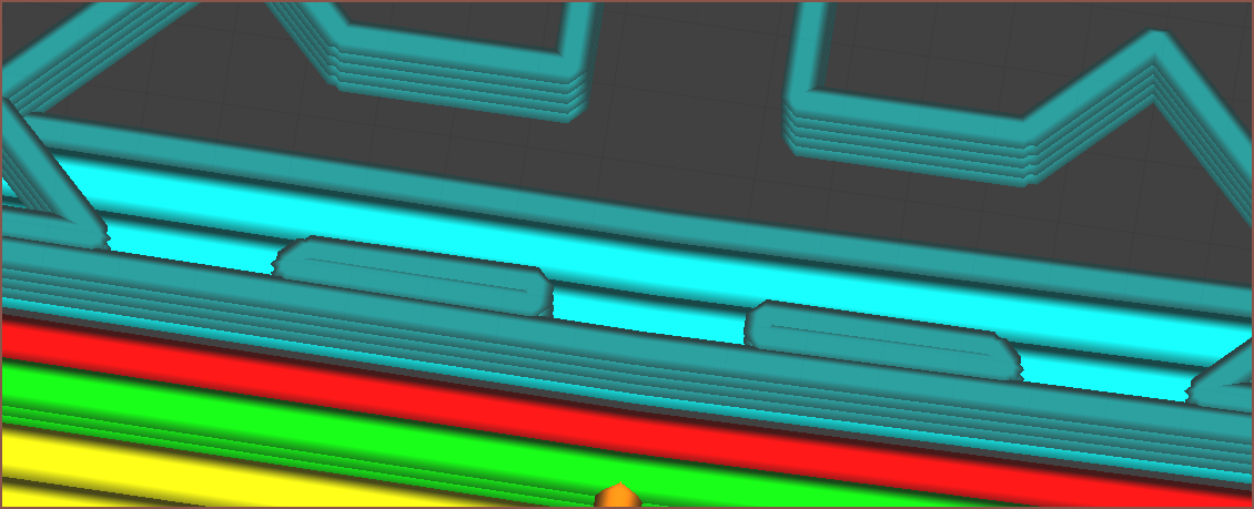
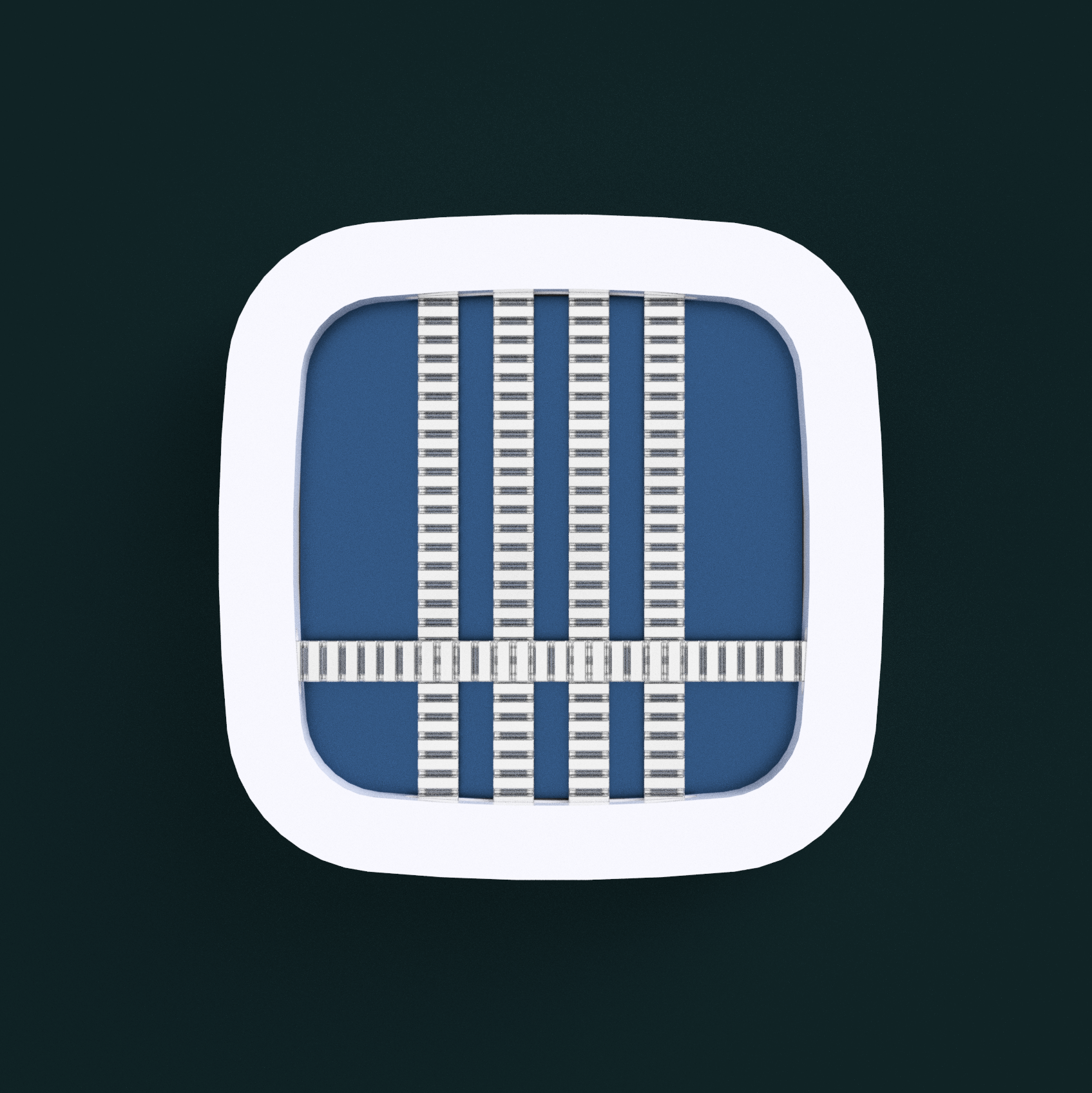
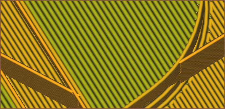
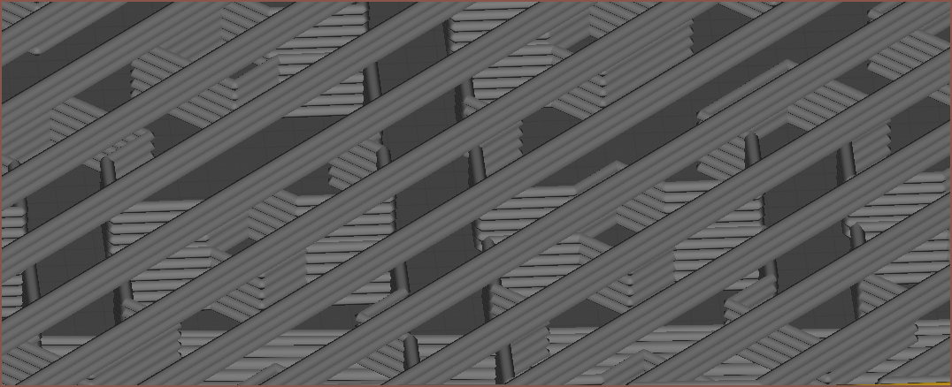
I noticed that this bottom layer that is just about the supports laid down much better than the first time. The only issues were those long gaps that are in the same direction as the layer lines. At least now I know why my first supports were so bad using ZigZag:
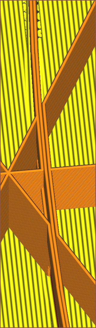
Unfortunately, "Support Infil Line Directions" only works on patterns such as Zig Zag, and had no effect on the Cross pattern. It's possible that I can use a support interface roof and set "Support Interface Line Directions" to "[45]" to produce the below pattern, however something like 23 (I can't use 22.5) would need to be used since there are still long gaps in the Cross pattern for 45 degree angles:
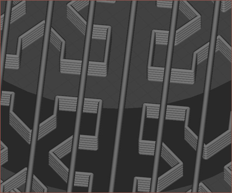
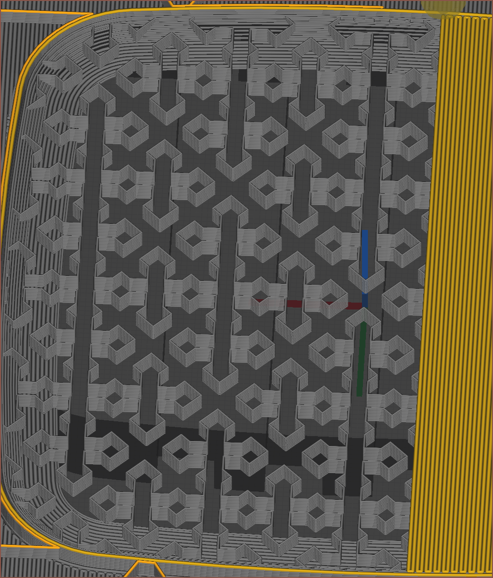
The sag isn't that bad, and this print is probably going to be one of the largest areas that even need support, so I think I'll be fine with the Cross pattern at 15% fill.
I did notice that the skin didn't really attach to the perimiter, so I've increased "Skin Overlap Percentage" from the default 5% to 10% (the same as the default "Infill Overlap Percentage".
Trying the second attempt
So the print finished as I was writing this log.
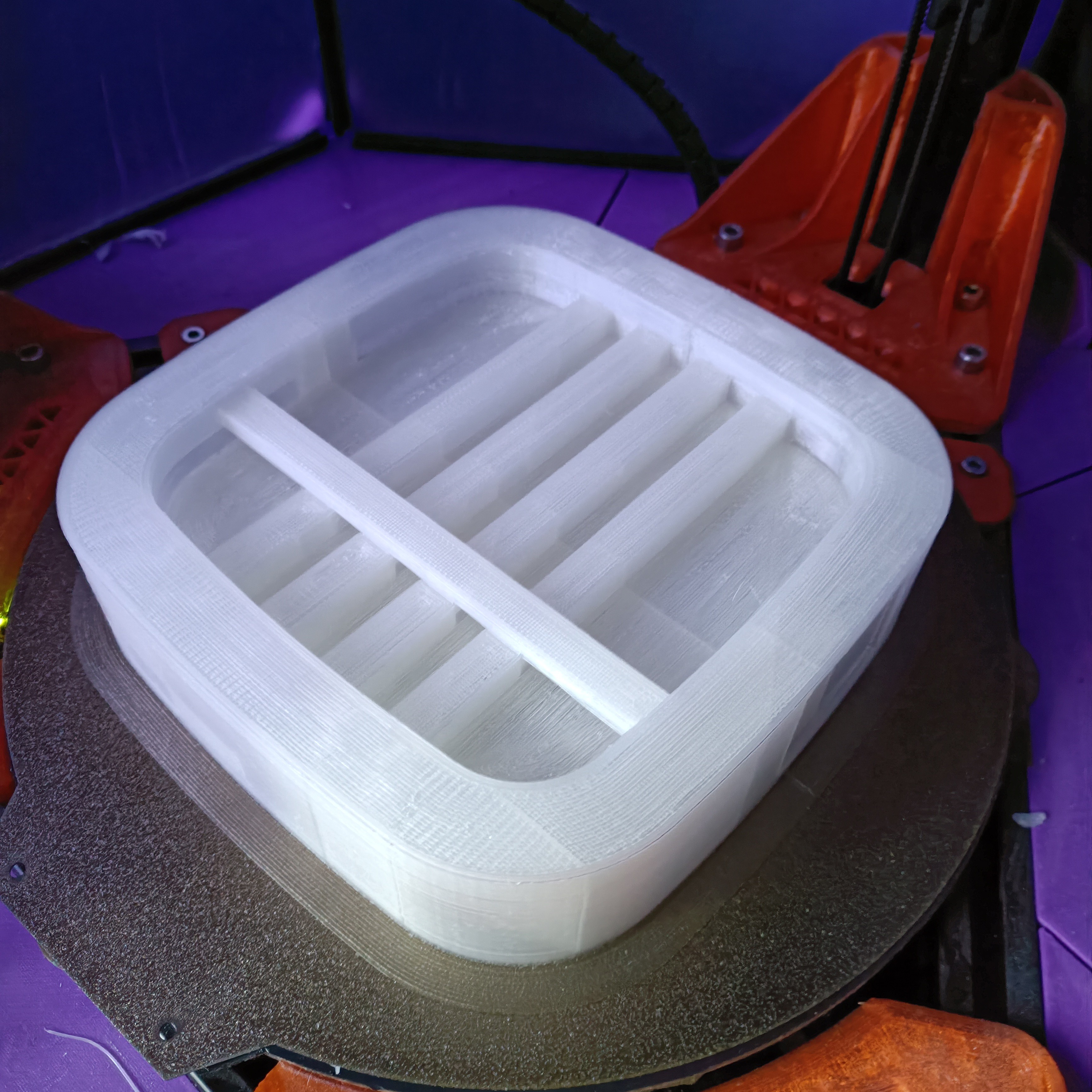
It certainly stuck better and has less warping, so I'll continue to use a bed temperature of 54C going forward. The support also looks good:
Unfortunately, the support has become harder to remove. The long, unsupported sections also sag and detach from the rest of the otherwise good looking underside. I might try 45 degree zig-zag with no outer wall next time.
The actual feel of the layout feels fine, although my thumb is still hitting on the corner. Reducing the radius also makes the device look sharper-edged. I've only been able to reduce from 20mm to 18mm, as even 15mm looks kind-of sharp.
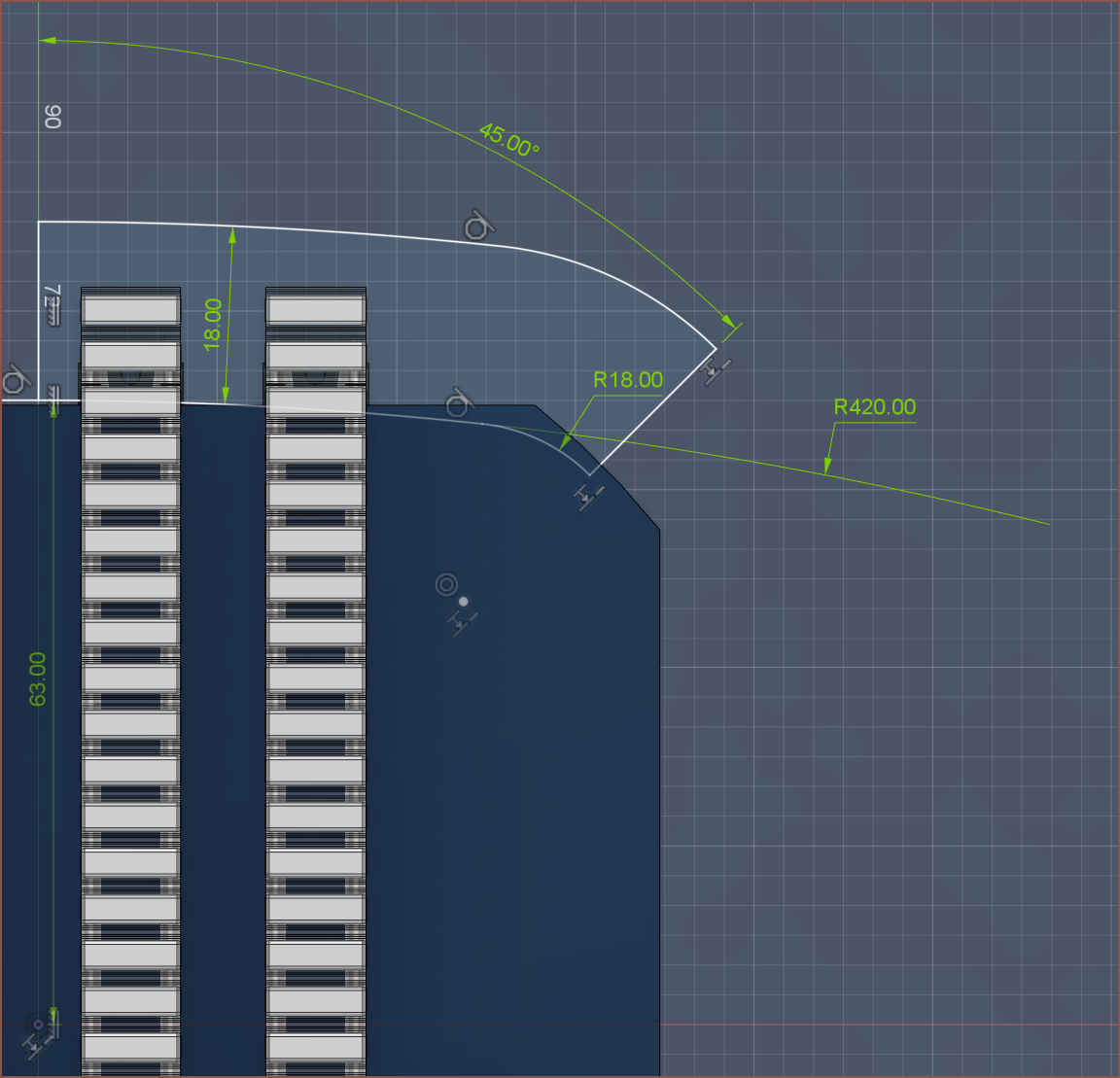
The solution is probably to increase the inner radius from 63mm to 64 or 65mm.
Here's a size comparison with my "Let's Split" keyboard:
Discussions
Become a Hackaday.io Member
Create an account to leave a comment. Already have an account? Log In.