 jimshortz
What Is It?
The Intel SDK-85 is a single board computer trainer from Intel. It is very similar to the MOS (later Commodore) KIM-1 in that it features a keypad and 7 segment display. 2K of ROM and 256 bytes of RAM are provided by two multi-function chips (8155,8755) which also provide a generous 36 GPIO ports. The board can be programmed using either the keypad or via a 110 baud serial port.
The left half of the board is a "playground" area where the user can add their own chips (via wire wrapping). Expansion options exist to double the RAM and ROM, and expand to a whopping 72 GPIO ports plus a timer.
My Story
The board was acquired from a local ham for a small cash sum. Several years ago I missed an opportunity to get a Heathkit ET-4000 (it was literally purchased by the person in front of me in line for $20). When I saw this SDK-85, it was a "buy first, ask questions later" situation. As such, I am unsure of its history. I didn't even think to make a note of who I purchased it from.
The kit was in very good condition. The original box, manuals, and 8085 reference card were included (the latter being very important). It was a basic kit (no expansions) but had been fully assembled. The only thing not attached was the red lens, but it was included.
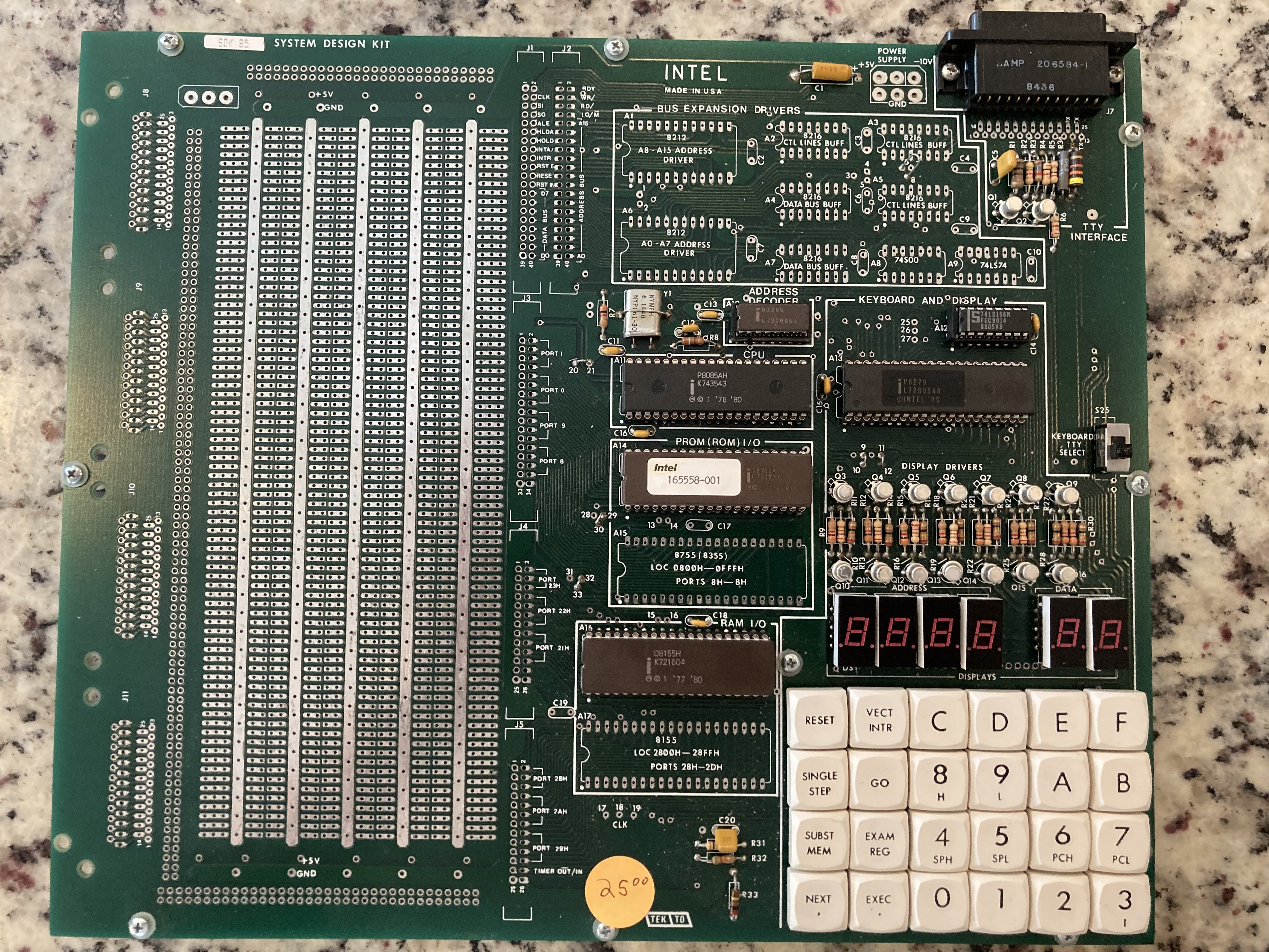
Fig 1 - The board as delivered
No connectors were included, so I soldered some 18AWG zip cord into the connector holes. I connected it to my bench supply and was greeted with an "8085" prompt after applying power. All of the keys appeared to work and no smoke came out. I keyed in the "4 digit hex counter" program from the manual and it worked correctly.
Next, I typed in the "decimal counter" example. This one did not work so well. After some debugging I determined that the problem was due to interrupts. Evidently, the authors of the manual had neglected to include instructions to clear out the RST vectors in RAM. After doing so, the program worked correctly and I was smugly confident about discovering their oversight.
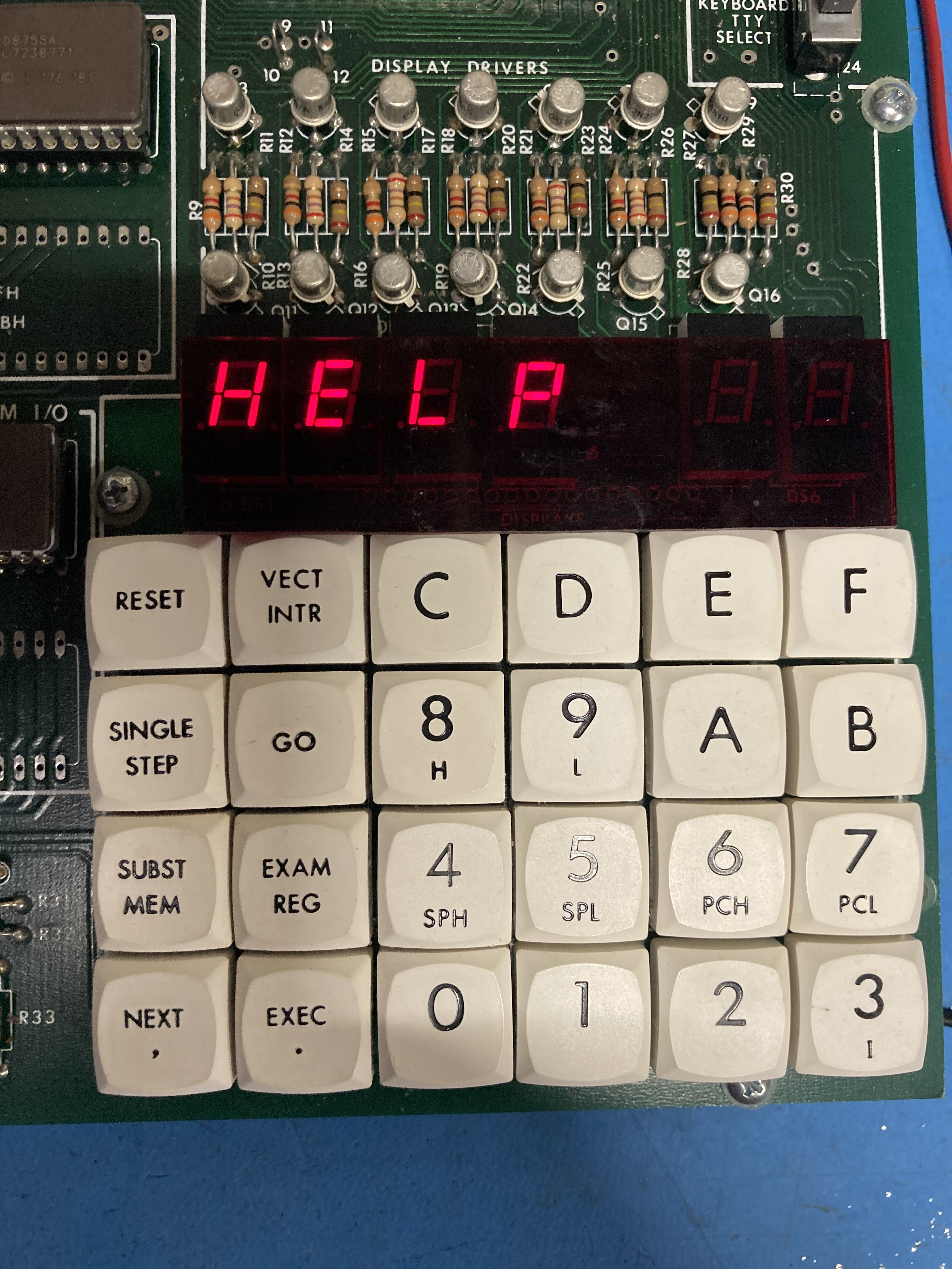
Fig 2 - An appropriate program from the manual
After some time, and having similar problems with other programs, I began to question my previous conclusion. I started reviewing the construction steps just to make sure the previous builder had done it correctly. On about the third read through, I discovered a mistake. On page 3-4, the builder is instructed to strap pins 3 and 5 together if using the basic kit. This step had been omitted. After applying the strap, all of the example programs worked correctly without modification. Omitting this strap was causing spurious RST6.5 interrupts to be fired, and my software changes had simply covered up the problem.
I also used some double-sided tape to attach the red lens. This was the original specification, though the suppled tape was long gone. I used some 3M tape left over from hanging a poster.
At this point, I now have a fully functioning "basic kit" with 256 bytes of RAM and 2K of ROM.
Discussions
Become a Hackaday.io Member
Create an account to leave a comment. Already have an account? Log In.