 jimshortz
Other than the DB-25 serial port, the SDK-85 comes with no connectors. However, the manual is quite complete and provides recommendations on page 3-5.
It is important to install the power connector for several reasons. First and foremost, you want to avoid accidentally revering the polarity which would likely destroy this vintage board. Equally important is to not mix up the +5 and -10V supplies as that would also destroy things. Lastly, being able to unplug the power allows for the board to be easily flipped over for soldering, wire wrapping, or inspection. I found myself flipping the board quite a lot.
I was able to locate the Molex power connectors from several sources. The easiest was a kit available from Digi-Key. I was able to assemble the connectors using an ordinary "automotive-style" crimper. I installed the male housing on the board and used the female housing for the power supply cable.
However, I did make a mistake in assembly - I used a male housing but female pins. I discovered this error when trying to connect the power cable which was male pins in a female housing. It was difficult to get the connectors to mate and then the pins pulled out of the female housing. I was able to work around it by jamming the wires into the pins without using the housing, but I need to fix this as I have negated the two most important benefits of the connector.
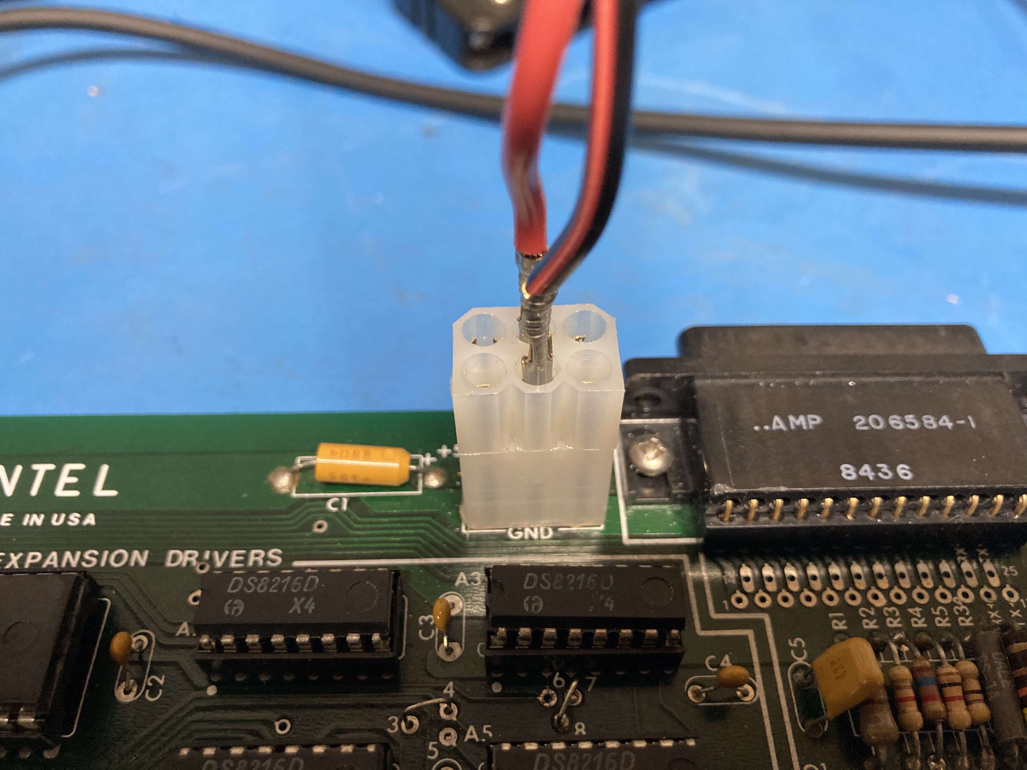
Fig 1 - The "hacky" power connector
I was unable to find the "spectra strip" connectors described for J1-J5. So, I used snap pins instead. I chose the extended length kind (Digi Key part S1052E-36-ND). This allows me to connect either an IDC ribbon cable up top, or use the bottom for wire wrapping. This also makes it possible to build daughterboards that plug directly on top of the SDK-85 and sit over the wrapping area.
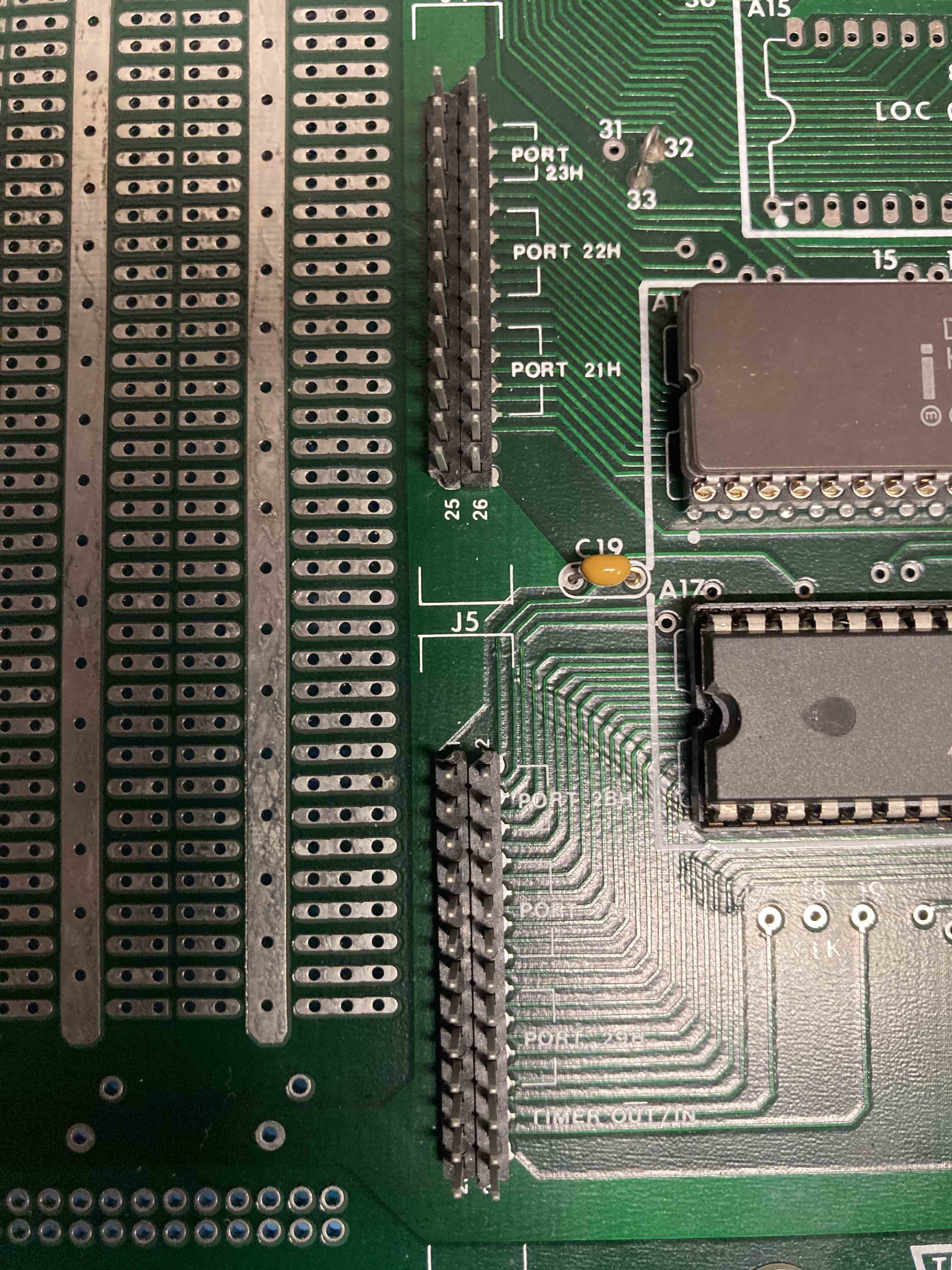
Fig 2 - Header pins installed in GPIO port
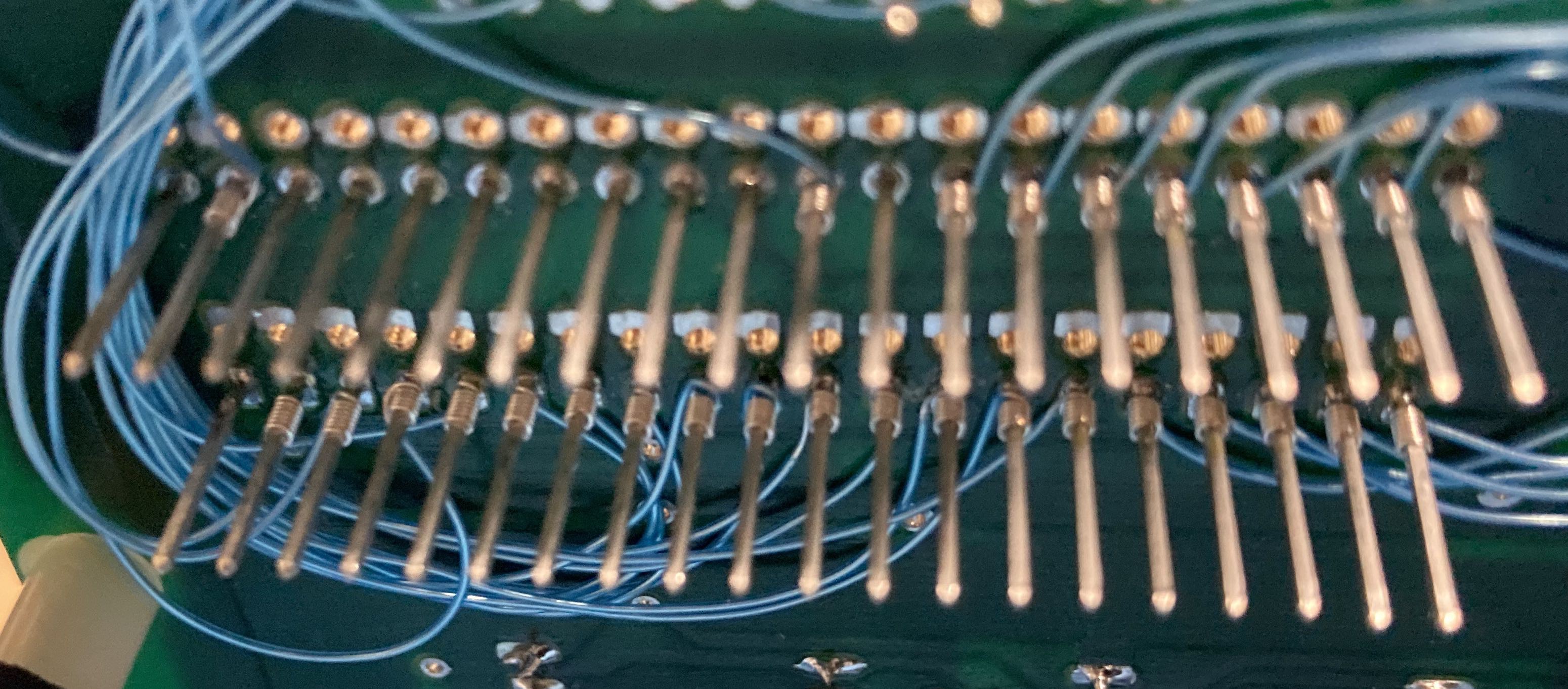
Fig 3 - Header pins used as wrap posts (underside of board)
Lastly, I used individual snap pins for the +5 and GND lines. This provides both an easy point for wire wrapping and also a place to connect test equipment topside.
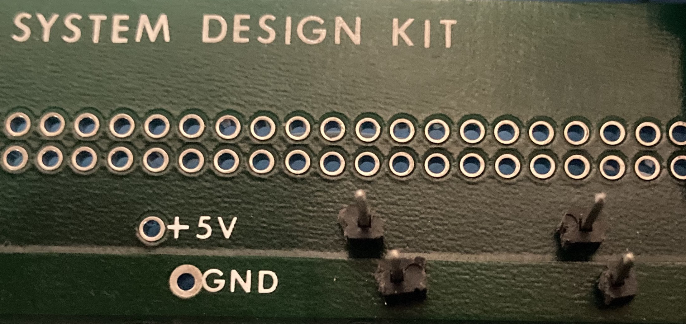
Fig 4 - Power pins
Discussions
Become a Hackaday.io Member
Create an account to leave a comment. Already have an account? Log In.