 jimshortz
As mentioned previously, the "basic configuration" consists of 256 bytes of RAM, 2K of ROM, and 36 GPIO lines. There are also three ways the board can be expanded:
* Add a second 8155 IC to double the RAM to 512 bytes. This also adds 20 additional GPIO lines and a timer.
* Add a second 8755 IC to double the ROM to 4K. This also adds 16 additional GPIO lines.
* Add bus expansion drivers to allow whatever the heck you want to be added to the prototype area.
These upgrades are independent - you can do any combination of them. It's also worth pointing out that if you perform the bus expansion upgrade, you can add generic 32K SRAMs and EPROMs giving you far greater amounts of RAM and a ROM that is both larger and easier to program. These generic parts are also much easier to acquire.
However, I chose to apply the 8155 upgrade as it was easy and I wanted the additional GPIO lines and timer port. Simon did not fit in the basic RAM and I didn't want to undertake a large upgrade until I finished that project.
I acquired the 8155, the 8212s, 8216s, and 74AC00 at the same time from a small vendor in the US with a healthy chip stash. You can also order them from eBay, but will likely have to use multiple vendors and possibly go overseas. It was much easier to just go to a single source. Not all of the chips were advertised on his site, but I contacted him via email and he did have everything I needed.
Installing the 8155 was straightforward, just solder in a 40 pin socket and plug the chip in. Or at least it should have been. After installing the new 8155, the system would no longer start. After a couple of agonizing hours of troubleshooting, I discovered the problem.
The SDK-85 is a 12 inch x 12 inch two layer board. The bottom layer is mostly ground pour. So, the ground pin of the 8155 had quite a large heat sink attached to it. This resulted in a faulty solder joint that my aging eyes were unable to detect on the first (or fifth) inspection. After cranking the heat and re-flowing, I was able to get a working system again with double the RAM.
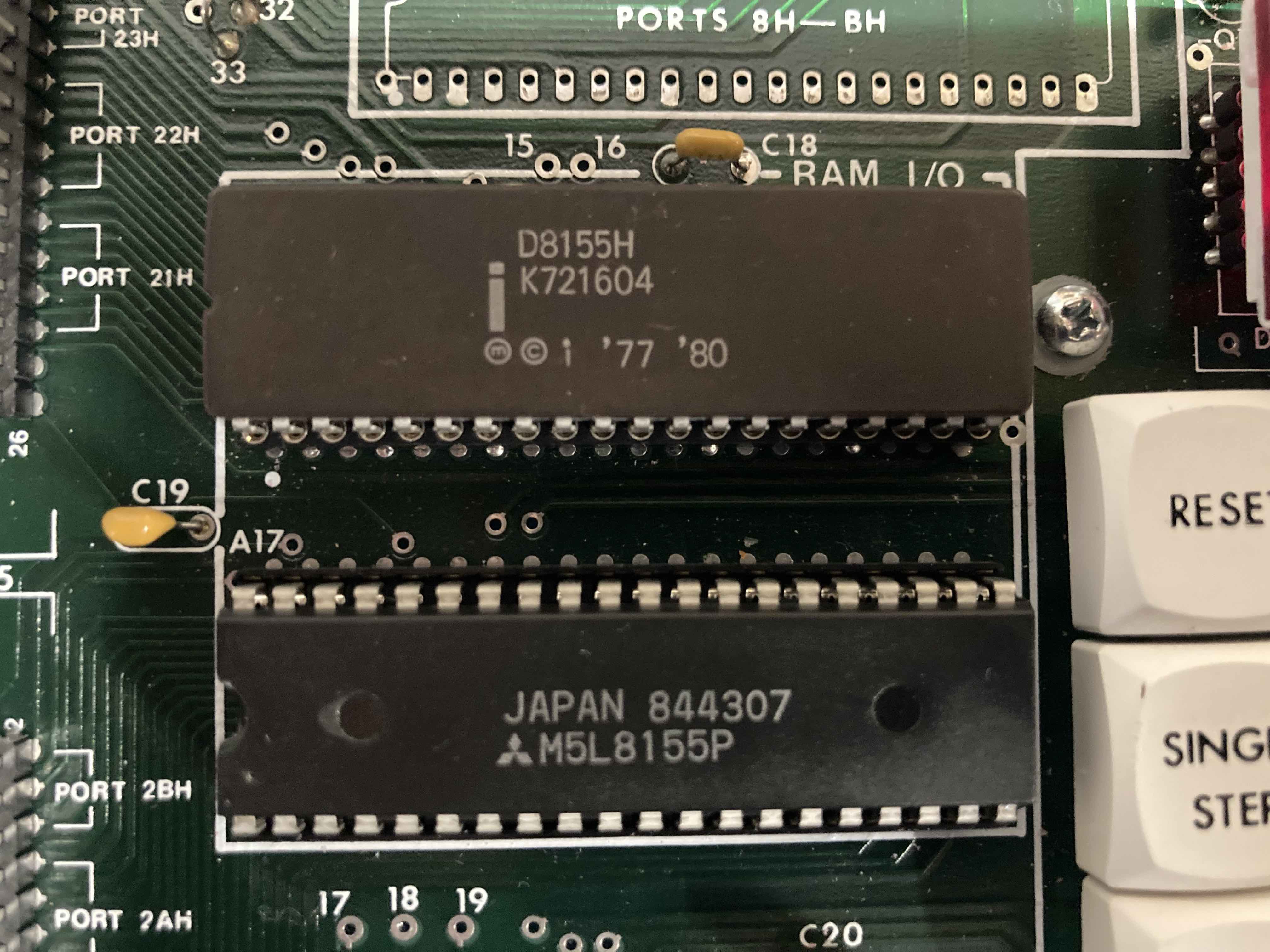
Fig 1 - The second 8155 installed. Obviously a second source (Mitsubishi)
Some weeks later I added the bus expansion chips as well. This involves adding nine chips to the board:
* Two Intel 8212 8 bit latches (for demultiplexing the address lines)
* Five Intel 8216 buffers (for driving the big banks of RAM folks would have had in the 1970s)
* A 74AC00 and 74LS74 for glue logic
Each chip was installed with a socket and also required a 0.1uF disc capacitor for bypassing. Strapping changes were also required as described in the manual. After installing all the new chips and capacitors I tested them by booting up the system and everything worked correctly. Little did I know that one of the 8216 had a bad ground pin connection caused by the heat sinking problem again. This would rear its ugly head during a later phase.
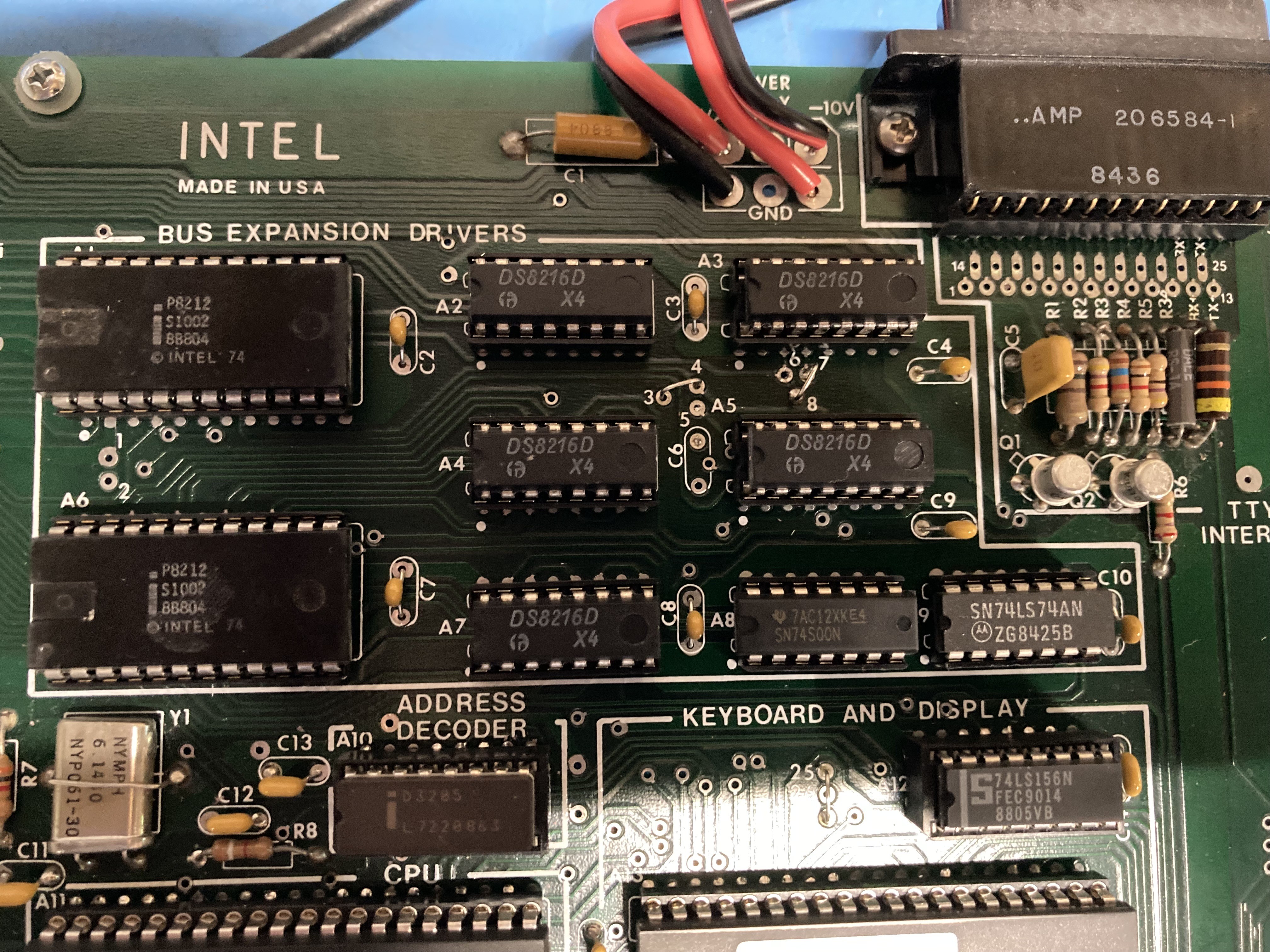
Fig 2 - All 9 bus expansion chips installed
The bus expansion upgrade by itself does nothing. What I added is complex enough to get its own post which is forthcoming.
Discussions
Become a Hackaday.io Member
Create an account to leave a comment. Already have an account? Log In.