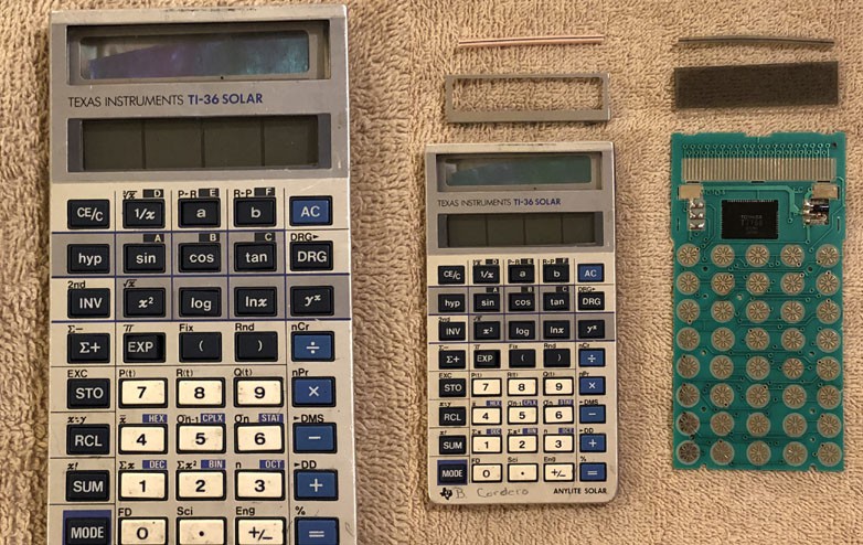
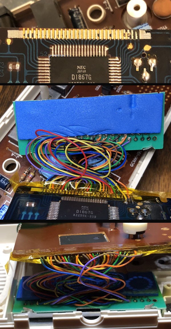
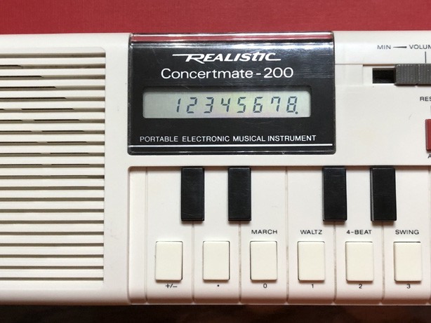
• Casio VL-1 LCD repair log

    rbroniak09/18/2023 at 16:30 0 comments

    Before you look through this repair log, you may want to checkout davedarko's log - Repairing the LCD of a Casio VL-Tone VL-1.  I looked everywhere to try and find some info about repairing my Casio's LCD and this was one of the few pages I found with helpful information. 

    When I received my Casio from Ebay, (thanks andwe_928236) it had 3 distinct problems. A variable resistor that controlled the main supply voltage was totally shot - disintegrated! A small pcb trace was cracked that prevented 3 of the keys from working. And, the subject of this repair, the LCD did not show any life whatsoever.

    I easily replaced the resistor and fixed the pcb trace, but the LCD would prove to be much more challenging.

    After reading through Dave's log, I wondered if an old calculator could provide what I needed. I have an extensive vintage calculator collection and I soon found a broken TI-36 solar that I knew would be suitable.

    The LCD in the Casio is connected by a flimsy flex cable with 29 carbon traces emmbedded into the plastic - (see Dave's log). It was, and I guess still is, a very common way to connect an LCD to a circuit board. But over time the connection becomes brittle and the adhesive that holds the flex cable to the LCD and PCB gets old and falls apart. In my opinion, the connection used by many calculators - including this one, has better longevity. It uses an elastic zebra strip that press fits up against the circuit board to make the connection. A small tin frame bracket fits over the glass LCD to press the contacts together.

    I used some isopropyl alcohol to remove the adhesive from the Casio glass. I could see the contacts on the glass and I lined up the 2 pieces so that the Casio's LCD was aligned with the contacts on the calculators circuit board. I trimmed the board - and this is where I was extremely lucky - so that it would eventually line up perfectly with the display cutout in the front bezel.

    Now the next question was - how will the new circuit board fit into the Casio VL-1 case? Surprisingly it didn't take much modification to get the board to fit into the case. And here again, I think I was just lucky to trim the case exactly right.

    So now it was time to get out the trusty 'ol soldering iron and get to work to make the connections from the display board to the main PCB of the VL-1. I used 30 AWG wire wrap wire in 8 colors to make my connections. It's a good idea to use a small wirewrap wire stripper to strip the ends to keep the wire from getting nicked. A nicked wire can easily break off.

    The main PCB of the Casio still had a few places where the old adhesive needed to be removed. After a bit of scraping I was able to connect the two boards together. This picture shows the results after the first atempt. Later, I trimmed all the wires to about half the length that you see in the photos. Also, I reoriented the direction of the wires from the Casio keyboard PCB so that they point 180 degrees from the position in the photos. The unit then fit together much better after I did that.

    I checked the display to see if it was working before I put it back together. The LCD was working great, except that I had to apply a bit of pressure to the glass to get it to show up visibly. But as it turns out, once the display board was put into place and the keyboard PCB was screwed down tight on top - there was plenty of pressure to keep all the segments visible.  So here is the final photo of the keyboard after everything was put all back together.

    I still can't believe that it lined up with the bezel as well as it did. Thanks for reading my repair log!