Arduino Latency Meter
A simple DIY Arduino-based device to measure the input-to-action latency in 3D games.
https://github.com/EugeneFainstain/ArduinoLatencyMeter

1. How it works
a. It works differently
- Unlike other common HW latency meters, this device doesn't measure a "click-to-photon" latency, but rather an "aim-to-photon" latency.
- The device presents itself to the PC as a mouse, and sends a mouse movement (not a click!) message.
- Once the message is sent, the device measures the time until the image on screen changes.
b. Advantages over other latency metering devices
- You don't need bullets to measure latency, so you never run out of ammo - you can (quickly) make as much measurements as you wish. As a result, the device can work autonomously to collect unlimited number of measurement samples, reaching a much higher accuracy.
- The measurement doesn't rely on the muzzle flash animation, which (depending on developer) may be rendered with a delay, producing incorrect results.
- You can measure latency in games that don't shoot guns (e.g. shoot arrows or explore)
- You don't need to place the device in the middle of the screen every time. It is unobtrusive enough that you don't even have to take it off.
- The device requires only one connected wire for operation.
- The device can even estimate the effective framerate - something the other devices cannot do.
- And of course, last but not least - the device is open source, cheap, and easy to make!
c. So what about the "click-to-photon"?
- The device can also measure "click-to-photon" by appropriately modifying the software it's running, if one wanted to.
2. Building the device
- See building instructions below in the "Instructions" section.
3. Device placement
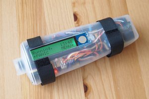
- The device should be placed at the top edge of the monitor, approximately in the middle. I mean, it is also possible to place the device in the corner (like I did in the photo at the top) - but it ended up being easier to find suitable measurement scenes if the device was placed in the middle - see a section called "choosing the right scene for measurement" below.
- Attach a piece of Velcro to the top of the monitor bezel to hold the device.
- IMPORTANT!!! Be careful with the USB connector on the board - it's rather flimsy and will break off if you try to apply torque force to it. This mostly happens when you try to unstick the device from the Velcro by pulling on the wire towards yourself. :) Consider yourself warned...

4. Operating the software
a. Programming the Arduino board
- Download Arduino IDE from here: https://www.arduino.cc/en/software
- Use it to open the script - ArduinoLatencyMeter.ino
- Connect the board, use Tools -> Port to select the correct port
- Select the "Arduino Micro" board from Tools -> Board -> Arduino AVR Boards -> Arduino Micro.
- A word of caution: this specific board can be slightly bricked by selecting the board type incorrectly - but this shouldn't be possible with the current code. In any case, it can be unbricked as well, but it's a bit of a hassle.
b. Using the Arduino IDE to interact with the software
- Once the board is programmed, open the serial monitor via Tools -> Serial Monitor. You should see a printout that looks something like this:

Here is what this means:
- The latency meter - speedwise - is equivalent to a high-speed camera running at about 55,000fps.
- To start the measurement with a delay (to have enough time to Alt-Tab to the target application) - enter the number of timeout seconds in the input edit box (the one just above the printout).
- An alternative (and more convenient) way to start and stop the measurement is to push the wire on the board to close the circuit. This way you don't need to Alt-Tab.
- It helps to have a secondary monitor - with the Arduino IDE running there - to see the measurements appear in real time.
- Any serial terminal can be used instead of the Arduino IDE - once the board has been programmed.
 Eugene Fainstain


 Muhammed Azhar
 RemoteMCU