 dennis
Adding limit switches to the ST1000 and ST2000 is a great way of preventing serious damage to these otherwise wonderful units.
In my case the damage was already done. The motor had stripped the teeth of the toothed belt that drives the gears, and even stripped the teeth of one of the nylon gears themselves. Even the seal and outer bearing guide had been cracked on both sides. The files are hosted at printables for your convenience and mine (so I don't have to maintain my 3d printing projects in multiple places).
Adding these switches will prevent your unit from stripping off toothed belts etc
The 3D printable files are at Printables:
https://www.printables.com/model/570906-raymarine-st1000-tiller-autopilot-limit-switch-car
The 3D source drawings are at OnShape. Note that you only need access to this (free) if you want to edit your own version or access the 3D animated model:
https://cad.onshape.com/documents/ff892cc9957fb0d175a6a223/w/027790e8fd4758f3be9a786d/e/4644be35b096e6c55c23fbe9
(the OnShape document title is ST1000 LimitSwitches)
YouTube step by step walk-through for those who need it: (Sorry about the low quality video, I tried but no longer have the proper gear):
This hack was inspired by:
His video is much better quality and WAY MORE concise but his mod is technically more involved!
Another major source of inspiration for this was the following site:
https://www.cruisingonstrider.us/ST1000mods.htm
All source files and instructions are Open Source: GPLv2 or later.
Photos depicting a light grey / white printed unit are used with permission of the photographer Danny J. Mydlack who reserves all rights.
 ProgressTH
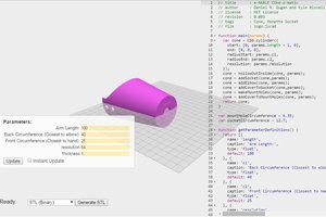
 Daniel R. Dugan
 Thomas Suarez