The purpose of the components used are;
▫ IC: The IC, or integrated circuit, is the central component of the fire alarm system. It
processes the signals from the other components and controls the operation of the system.
▫ Arduino Uno: The Arduino Uno is a microcontroller board that is programmed to control the operation of the fire alarm system. It receives input signals from the other components and generates output signals to control the LCD display, buzzer, and other components.
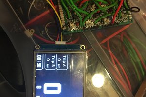
▫ LCD Display: The LCD display is used to display important information about the fire alarm system, such as the temperature, smoke level, and alarm status.
▫ Germanium Diode: The germanium diode is used to detect changes in temperature that indicate the presence of a fire. It is connected to the Arduino Uno, which processes the
signals from the diode and activates the alarm if necessary.
▫ Smoke Sensor: The smoke sensor is used to detect the presence of smoke particles in the air. It is connected to the Arduino Uno, which processes the signals from the sensor and activates the alarm if necessary.
▫ Buzzer: The buzzer is used to sound an alarm in the event of a fire. It is connected to the Arduino Uno, which activates the buzzer if the temperature or smoke level exceeds a certain threshold.
▫ Resistors: They are used to ensure that a signal is at a known state, either high or low, when no input is present.
▫ Capacitors: Capacitors are used in conjunction with resistors to create timing circuits for various purposes, such as activating a delay before the alarm is triggered.
▫ Transistors: They are used to amplify weak signals from sensors or other sources to a level where they can be processed by the IC or other components.
3.3 Fire alarm system using germanium diode and smoke sensor circuit design
The fire alarm system using germanium diode and smoke sensor works by detecting the increase in temperature and presence of smoke particles. The DR25 germanium diode is used as a heat sensor and will conduct only when the temperature is above 158 degrees Fahrenheit. It is connected to a transistor in reverse bias, which keeps the transistor turned on until the temperature threshold is reached.
Once the temperature is above 70 degrees Celsius, the resistance of the DR25 diode drops to 1k ohm, turning off the transistor and making the reset pin of the 555 timer go high. This generates an output at pin 3, which triggers the alarm through the buzzer.
In addition to the germanium diode, a smoke sensor is also used to detect the presence of smoke particles. When smoke particles are detected, current flows and triggers the alarm through the buzzer. Multiple DR25 diodes and smoke sensors can be used in parallel and placed in different rooms to detect fires more effectively. Overall, this system provides a reliable and effective way
to detect fires and alert occupants to potential danger.
If the smoke value in any room is greater than 500 (indicating the presence of smoke), the LCD displays the corresponding message ("Room 1: Fire!", "Room 2: Fire!", or "Room 3: Fire!"), activates the buzzer, and waits for 1 second. If there is no smoke detected in any room, the LCD
displays "All rooms clear" and deactivates the buzzer.
In addition, the program checks if the timer input is HIGH, and if so, activates the buzzer for 5 seconds and displays "Room on Fire!" on the LCD. The program then loops back to the beginning and repeats this process.
 DIY GUY Chris
 borsaci06
 Lithium ION