 Dave Collins
REV3 Works and synchronization scales exactly as expected!
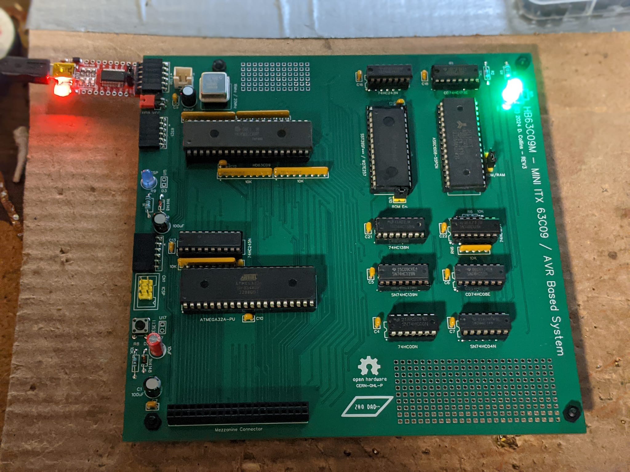
In short, the REV3 prototype is running at 20MHz. All of the
underlying functionality is synchronizing, scaled up from 16MHz with
zero issues. I am ecstatic and want to thank PCBWay for getting the
prototype to a stable state by again covering a 2nd run of
the mini ITX PCB. They have always been a wonderful partner in retro
and I would not be able to operate nearly as quickly as I do without
their help.
The problem of the REV1 Prototype:
What we learned from REV1 specifically is, using the AVR to Clock
the CPU is bad because we don’t know (inside the context of the
code) where the CPU clock is at when we send the IOGNT_ signal as it
is interrupt timer driven. Generally the best we can do is guess, and
insert a delay (as the AVR in REV1 was clocked at 16 Mhz and the CPU
was clocked at 4Mhz). Guessing is bad as there is, turns out – a
lot that can happen to delay or decrease the period of time the AVR
takes to finish this process. This causes a bit of instability and
made it generally impossible to move forward on optimizing things.
How does the AVR share the bus with the HD63C09?
The bus arbitration was switched from active arbitration (REV1) where delays were used to insure the IOGNT_ was held long enough to prevent MRDY from bouncing, to passive synchronized arbitration (REV2 and REV3). Essentially what this means is, both CPU's are using the same system clock and so every 4 cycles they finish their current cycle at the same time. To really understand requires some explanation, This all comes down to the specific timing of the 63C09’s decode cycle.
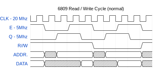
The 63C09 creates the quadrature clock’s (E & Q) which are
90 degrees offset from each other. In the case of the HB63C09M these
clocks run at ¼ the system clock due to a simple internal clock
divider that uses a set of J/K Flip Flops (each flip flop divides by
2). The 63C09E (‘E’ for external) generates this clock external
to the chip, which opens up some of the 40 pin package for extra
signals which are useful for more traditional bus arbitration. Both
CPU’s have the option of using a clock stretching circuit which
allows the designer to “hold over” or stretch the clock by up to
5uS. This 5uS limitation is to allow the CPU to refresh its internal
dynamic registers to avoid data corruption. I briefly went over
this in REV1 architecture overview.
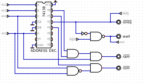
While significant changes have occurred within the selection chip set, the request grant circuit remains consistent. In this circuit, the AVR typically keeps the IOGNT_ signal high, except when it intends to relinquish control of the data bus to the CPU. When the CPU reads or writes to 0xA000 – 0xAFFF, this generates an IO request via the address decoder. Once the IO request is initiated, the address decoder generates a low signal that, after passing through an inverter to one input of the NAND gate, sets the output low as long as the leg tied to IOGNT_ is high. This output is tied to the MRDY signal on the CPU and begins a clock stretch. This state persists until the IOGNT_ signal pulsed low by the AVR for exactly ½ cycle of E.
Simple enough right? But what if we release IOGNT_ before the IO
Request ends (less than ½ of E)? In short, we would have a problem.
Since it’s just a passive logic circuit it would compute the result
and pass it along to essentially the MRDY line causing it to bounce a
few nS before the IO request finishes – this may trigger a second
clock stretch early, or cause other unpredictable things to happen on
the busses or inside the CPU which usually just result in a non
working system.
So how can we take advantage of clock synchronization to fix this issue:
The advantage here IS the 5uS limitation – this sounds strange
however it is a fixed limitation regardless of the speed of the
system clock. The 63c09 can handle ~.6 to .75 instructions per cycle,
depending on the instruction. The AVR on the other hand can handle 1
instruction per cycle. Meaning running at 16Mhz it can perform 80
instructions in 5uS, and at 20Mhz it can perform 100. This might not
seem like a lot of overhead at first. However, when broken down into
single step IO requests like: Send a character to the UART, read the
value of a status register, or set the bank register to a value on
the bus; you can start to see the advantages. Furthermore, because
the AVR can flip a bit on and off in an internal register in exactly
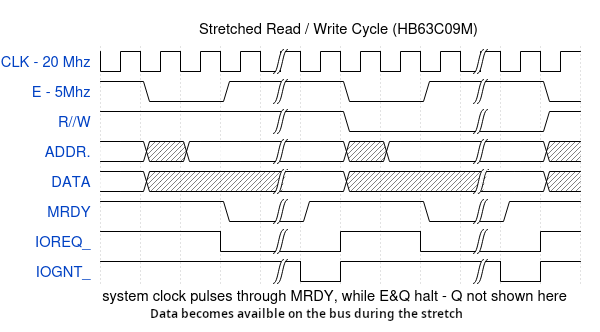
2 cycles of the system clock, we can see that this is exactly ½ of E! So, we can
be assured that when the AVR holds the IOGNT_ signal low, it will stay low
until just as the address bus is beginning to change. This means the
firmware does not have to do any of the timing, as the timing is
handled through synchronization.
Furthermore, no matter what happens inside the stretch be it 3 AVR cycles or 90, when we send the grant signal to the request grant circuit, the CPU's will continue on in a synchronized fashion without any worry that things will get out of sync.
SO, putting it all together:
Since each bit flip of IOGNT_ happens on each subsequent system pulse clock pulse, we can predict the amount of time each operation will take as the AVR can flip a bit in 1 cycle. We also know that E is held high and will almost immediately latch the data (in a read), or move on to the next cycle (in the case of a write) after MRDY ends the address bus has moved on. Because of this IOGNT_ will rise synchronous to the end of the IOREQ_ signal from the address decoder. This will happen in such a way, that even after the clock stretch, both CPU’s will still be synchronized. Furthermore, because both CPUs are tied to the same clock the result is exactly the same (within the maximums), whether or not the clock on the AVR is running at 4Mhz or 20Mhz. No state machine, no fuzzy timing math, no latching the data to later grab it off outside of real time; no running the MCU 300-400x the speed of the CPU to catch interrupts and data in real time. Essentially, to the CPU, the AVR is a regular old slow memory device, and to the AVR the CPU is just an 8 bit latch.
Thank you for going along with me on this journey, I hope that this has given a good groundwork for understanding the inner workings of the HB63C09M. If anything this technique is very easy to replicate and will work on any 8 bit CPU that has a clock stretching mechanism. Furthermore, the fully static Z80 and 6502 would not have to even worry about the length of the stretch period which opens up some very interesting options for sharing the bus.
For those that are interested I hope to have the design files in a
state that is ready to share by the next revision or two, until then
the design schematics are always available in the files section here. In addition I did a hack a day pages piece on how the mezzanine connection developments are going, if you'd like to check that out it is linked here.
Have a wonderful week, I will keep everybody up to date as things progress.
Discussions
Become a Hackaday.io Member
Create an account to leave a comment. Already have an account? Log In.