At this point we have something that at least proves out the concept of using TDR to measure soil moisture, but requires an oscilloscope to actually measure. To make this project work, I'll need to make a self contained way to measure that timing difference and it also can't cost much. So I want to avoid any ADC based based designs and instead focus on comparator and timing based designs.
The first design I attempted to replicate was from an EDN article. There are some low res partial schematics in the article that I recreated:
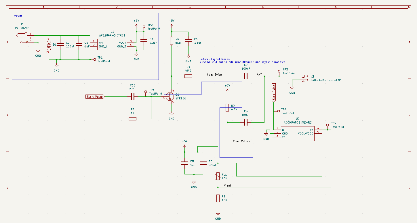
And also the PIC24F based digital section:
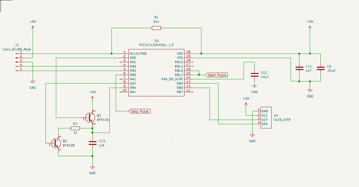
Which resulted in the following layout:
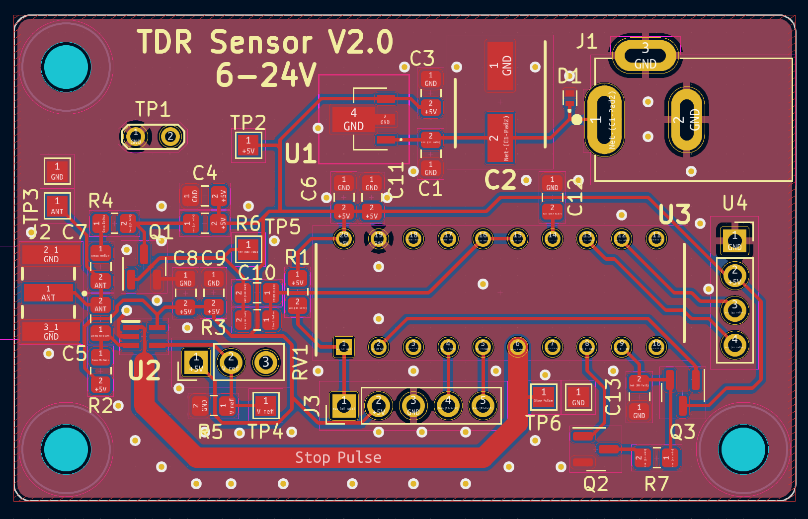
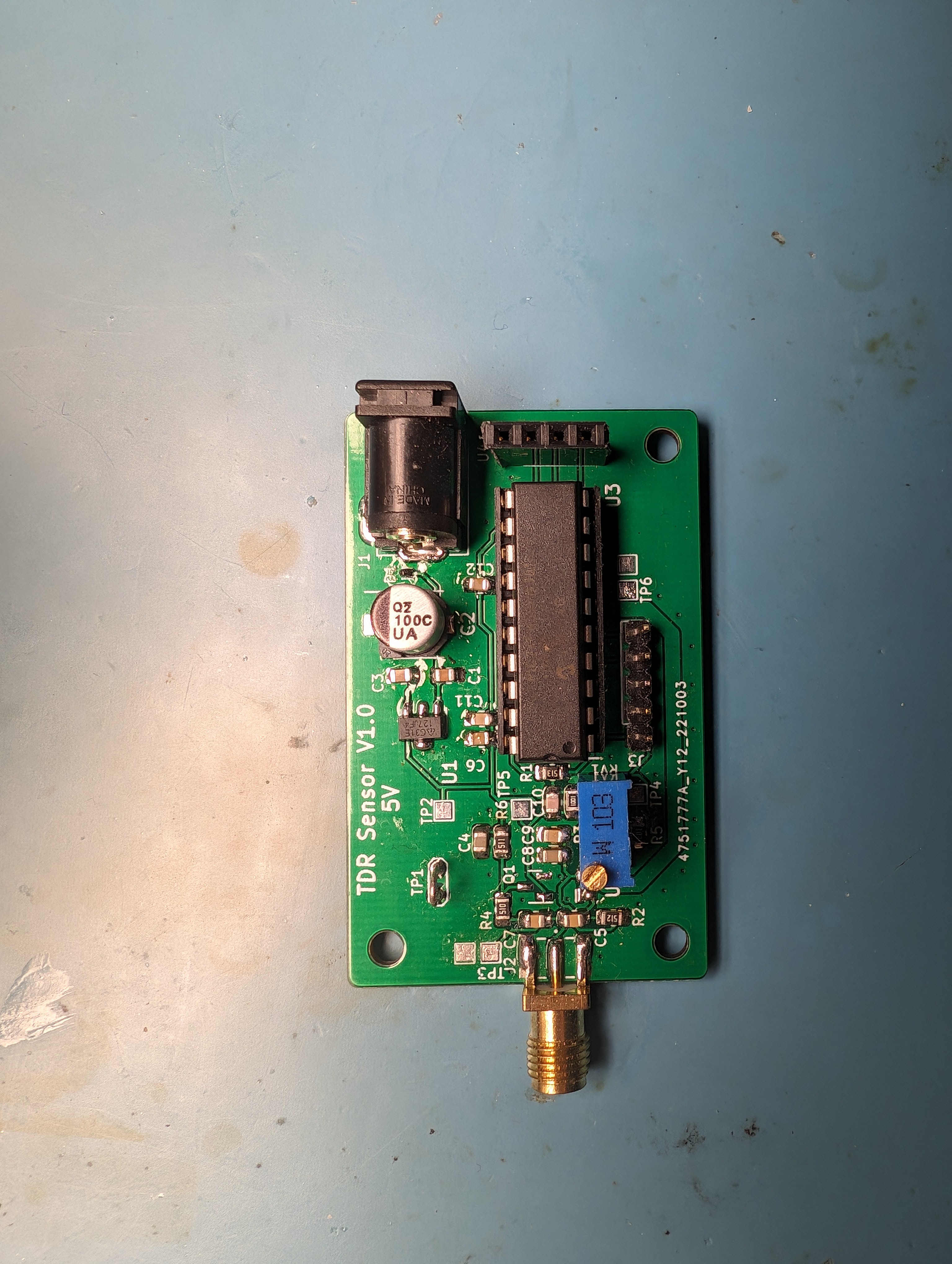
If you look closely, you may notice some unpopulated parts. I didn't take a picture until after I had already harvested a few components for the next version. There was a next version because this design ended up not having the resolution I needed to detect the differences between moist soil and slightly less moist soil. In the end it could measure a delay change of about 500ps which wasn't enough to reliably detect the moisture difference over a day.
So even if it didn't work out, I learned a few things while working with the PIC microcontroller and the CTMU. As mentioned in the article, the PIC has a current source it can start and stop charging a capacitor with. It then can measure the voltage on that cap to determine how much time has passed. Even with the current source set to the highest setting and using just the internal capacitance, the charge was too small to get an accurate reading. Also, the documentation on how to set the flags to get the right charge range where incorrect and had to be determined experientially.
The code is pretty simple and mostly configuration, so I'm including it here for completeness.
#define RANGE_5_50uA 1 // 5.50uA
void CtmuTimeConfig(unsigned int range, signed int trim)
{
    // Step 1 Configure the CTMU
    CTMUCON1 = 0x0000; // Disable CTMU
    CTMUCON1bits.TGEN = 0; // Disable Time Generation mode
    CTMUCON1bits.EDGEN = 1; // Edges are enabled
    CTMUCON1bits.EDGSEQEN = 1; // Edge sequence enable
    CTMUICONbits.ITRIM = trim; // Set trim
    CTMUCON1bits.CTTRIG = 1; // Trigger output enabled
    CTMUICONbits.IRNG = (range & 3); // Set range
    // This line does not apply to all devices
    //CTMUCON2bits.IRNGH = (range>>2); // set high bit of range

    CTMUCON2bits.EDG1MOD = 1; // Edge mode
    CTMUCON2bits.EDG1POL = 1; // 1 - rising edge 0 - falling edge
    CTMUCON2bits.EDG1SEL = 2; // 8 = CTED13 Pin 6 || 2 = CTED2 pin 15
    CTMUCON2bits.EDG2POL = 0; // 1 - rising edge 0 - falling edge
    CTMUCON2bits.EDG2MOD = 1; // Edge mode
    CTMUCON2bits.EDG2SEL = 8; // 8 = CTED13 Pin 6
//    CTMUCON2bits.IRSTEN = 1; // enable reset by external trigger
//    CTMUCON2bits.DSCHS = 4; // ADC end of conversion

    // Step 2 Configure the port Ports
    TRISBbits.TRISB12 = 1; // Configure RB12 as a input CTED2
    ANSBbits.ANSB12 = 0; // disable analog on RB12

    TRISBbits.TRISB2 = 1; // Configure RB2 as a input CTED13
    ANSBbits.ANSB2 = 0; // disable analog on RB2

    TRISAbits.TRISA0 = 1; // Configure RA0 as a input
    ANSAbits.ANSA0 = 1; // Configure AN0/RA0 as analog
    AD1CHSbits.CH0SA = 0 ; // Select AN0

    // Configure the cap drain output pin
    TRISAbits.TRISA3 = 0; // RA3 as output
    PORTAbits.RA3 = 0; // Set output low

    // Step 3 configure the ADC
    AD1CON1 = 0x0000; // Turn off ADC
    AD1CON1bits.SSRC = 0; // 4 - CTMU is the conversion trigger source 0 - manual
    AD1CON2 = 0x0000; // VR+ = AVDD, V- = AVSS, Don't scan,
    AD1CON3 = 0x0000; // ADC uses system clock
//    AD1CON3bits.ADCS = 8; // conversion clock = 1xTcy
    AD1CON5 = 0x0000; // Auto-Scan disabled
    AD1CON1bits.ADON = 1; // Enable ADC
    AD1CON1bits.ASAM = 1; // Auto-sample

    // Clear CTMU Interrupt
    IFS4bits.CTMUIF = 0;

    // Step 4 - 6 Enable the current source and stop manual discharge
    CTMUCON2 &= ~0x0300; // clear the edge status bits
    CTMUCON1bits.CTMUEN = 1; // Enable the CTMU
    CTMUCON1bits.IDISSEN = 1; // begin manual discharge of cap
    PORTAbits.RA3 = 1; // Drain the external cap
    __delay_ms(10); // Wait for the drain to complete
    CTMUCON1bits.IDISSEN = 0; // stop discharge of cap
    PORTAbits.RA3 = 0;
}

static void config_ADC_ext_cap() {
    AD1CON1 = 0x0000; // Turn off ADC
    ANSA = 0; // Clear register select
    ANSB = 0;
    // Configure RB4/AN15 to read the voltage on external cap
    TRISBbits.TRISB4 = 1; // Configure RB4 as an input
    ANSBbits.ANSB15 = 1; // Configure AN15 as analog
    AD1CHSbits.CH0SA = 0b01111; // Pick AN15

    AD1CON1bits.ADON = 1; // Enable ADC
    AD1CON1bits.ASAM = 1; // Auto-sample
}

#define MAX_TRIGGER_CHECKS 100
/*
    Main application
 */
int main(void)
{
    char print_buf[128] = {0};
    // initialize the device
    SYSTEM_Initialize();

    SSD1306_Begin(SSD1306_SWITCHCAPVCC, SSD1306_I2C_ADDRESS);
    SSD1306_set_rotation(SSD1306_ROTATE_180);
//    SSD1306_Display();
//    __delay_ms(2000);
    SSD1306_ClearDisplay();
    SSD1306_DrawText(2, 7, "Hello, world!", 1);
    SSD1306_Display();

    // Configure the pulse output pin
    TRISBbits.TRISB13 = 0; // RB13 as output
    ANSBbits.ANSB13 = 0; // disable analog on RB13
    PORTBbits.RB13 = 0; // Set output low

    unsigned int result;
    CtmuTimeConfig(0, 0); // 550uA

    int count;
    int flip = 0;
    while(1)
    {
        count = 0;
        PORTBbits.RB13 = 1; // Trigger pulse
        PORTBbits.RB13 = 0; // Reset pulse
        // Wait for CTMU interrupt
        while(IFS4bits.CTMUIF == 0) {
            count++;
            // Bail if we fail to trigger
            if(count > MAX_TRIGGER_CHECKS) {
                CTMUCON2 &= ~0x0300; // clear the edge status bits
                goto main_loop_end;
            }
        }
        // Clear CTMU Interrupt
        IFS4bits.CTMUIF = 0;

        //config_ADC_ext_cap();
        // Make sure the interrupt is already cleared
        IFS0bits.AD1IF = 0;
        // Trigger ADC conversion
        AD1CON1bits.SAMP = 0;
        // Step 7: Wait for ADC interrupt
        while(IFS0bits.AD1IF == 0){}

        // Steps 8-11
        IFS0bits.AD1IF = 0; // clear the interrupt
        result = ADC1BUF0; // read ADC result

        CTMUCON1bits.IDISSEN = 1; // begin manual discharge of cap
        PORTAbits.RA3 = 1; // Drain the external cap
        __delay_ms(10); // Wait for the drain to complete
        CTMUCON1bits.IDISSEN = 0; // stop discharge of cap
        PORTAbits.RA3 = 0;

        CTMUCON2 &= ~0x0300; // clear the edge status bits

        // Write results to screen
        char format[] = "ADC: %d %s";
        int slen = sprintf(NULL, format, result, flip ? "." : " ");
        if(slen < sizeof(print_buf)-1) {
            sprintf(print_buf, format, result, flip ? "." : " ");
        } else {
            sprintf(print_buf, "Print too long");
        }
        SSD1306_ClearDisplay();
        SSD1306_DrawText(2, 7, print_buf, 1);
        SSD1306_Display();

main_loop_end:
        // Wait a bit
        __delay_ms(10);
        flip = !flip;
    }
    return 0;
}
I didn't write much in the way of documentation or screen shots of the experimental results since I was focused on getting it working, and since it didn't, I don't really feel like going back and setting it up again.
At this point it was back to the drawing board for the sensor side of the project, which we'll take a look at in the next log.
Discussions
Become a Hackaday.io Member
Create an account to leave a comment. Already have an account? Log In.
Wonderful to go thru your work. Recently I am building a tdr soil sensor for agri for a smart system. I see the AliExpress versions (MEC, JCXT) have their pcbs with an STM32L452RE, an lmv324, an rs485 and voltage regulators to measure soil conductivity, moisture and temperature. There is no signal generator like 74AC14 and the STM32L452RE they use works at 40MHz so there is no chance of getting pulses into or out of probes of 2-10ns. Your option to go for low cost is mine too. I aim to use Esp32 C3 with Lora (heltec chip) instead of stm/rs485 so the sensor sends data to wifi/bt/lora directly. Your choice of using a timing based ic and low cost adc inspires me too. It will be fascinating to get 4-10ns reflection for delta t for time to give moisture. That leaves one question: if we want to measure Electrical Conductivity and moisture than we will need both the rising peak height (VT/VR) and delta t. Avoiding a 1Gsps adc will not give the rising peak height? Or is there a way around? Hope to get an answer. Anyways liked your log a lot.
Are you sure? yes | no