The TDC7200 Time-to-Digital Converter chip came to my attention and despite it not exactly intended for this application, the basic functionality seems to be exactly what I need. It's intended to be used in something like a LIDAR system, where it measures the time between the outgoing pulse and the reflection. But the measurement resolution of 55ps with a standard deviation of 35ps should be more than enough my application.
So what I need to do is create a start and stop signal to feed into this chip and then read out the time of flight. The start pulse is easy, since I'm already generating that to feed into the Schmitt trigger to create the pulse, but the only twist is that the TDC requests the pulse instead of it just happening whenever. So, I wait for that with the RP2040 and then send out the start pulse.
Where I want to stop measuring is at the final reflection from the end of the PCB antenna. Since the TDC doesn't work off of voltage trigger level like an oscilloscope, I used a voltage divider to set the trigger level and a comparator to make a single step after that threshold is crossed.
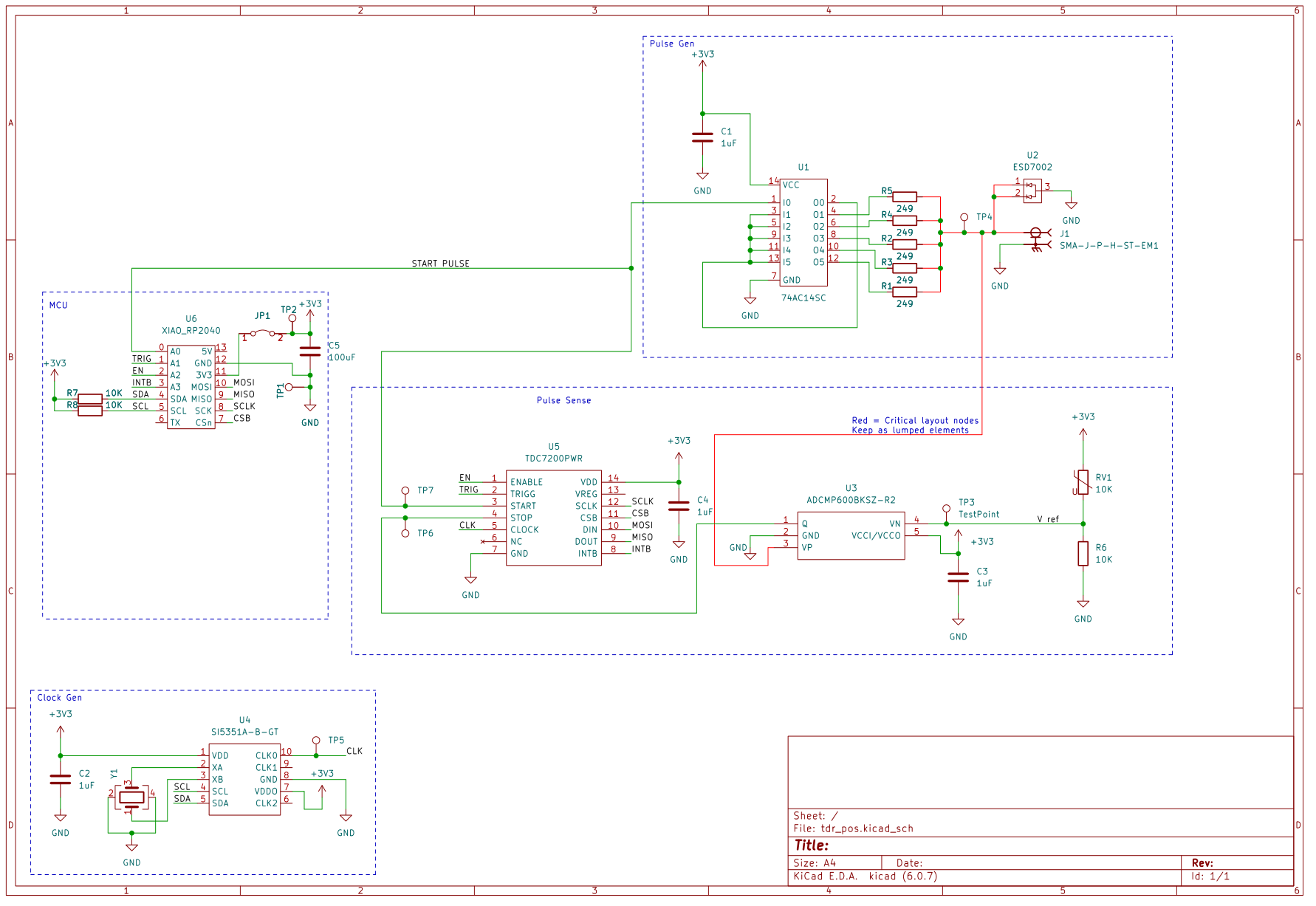
I picked a very fast comparator, but in theory this actually isn't required since the absolute time between the start and stop pulse isn't important since we are just comparing relative readings, not the absolute value. So a cheaper chip is certainly possible as long as the rise time is less than 1ns and the delay is fixed.
The TDC also needs a clock, which I generated using Si5351 which gives me the ability to try out various frequencies, but in the end I just used the datasheet recommended frequency.
The board in action:
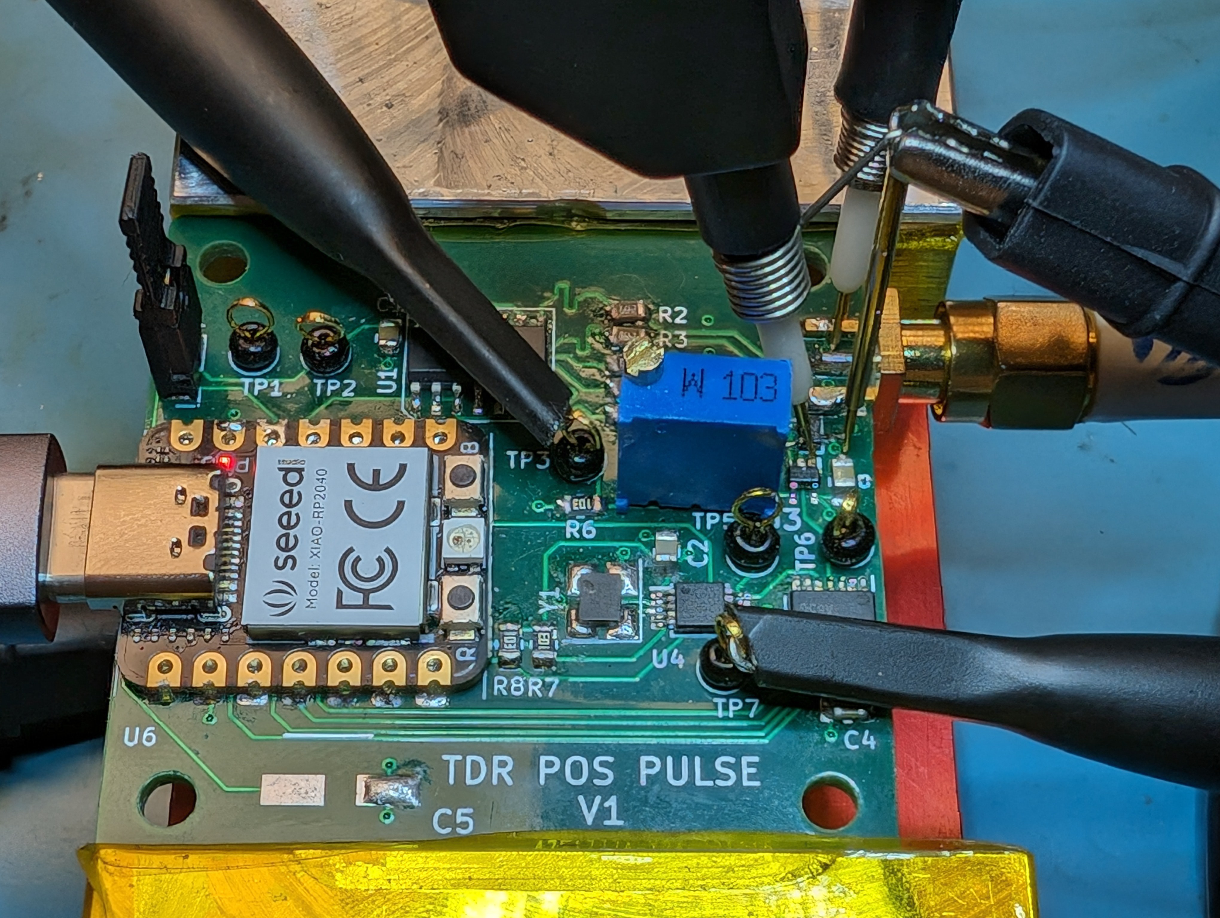
The SMA connector goes to the PCB antenna just sitting on the desk. I made a measurement that I saved to a ref (thin traces):
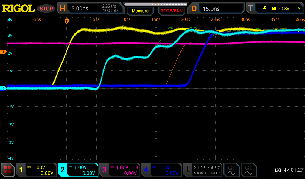
The yellow trace is the start pulse that then causes the light blue pulse to go to the antenna. The dark blue line is the comparator output and the magenta line is the trigger level. The light green thin ref line is the pulse with the antenna on the desk, so there is no extra step from the change in medium as the pulse goes down the trace. The comparator output with the antenna at that point is the orange ref line. I then covered the end of the antenna with my hand, causing a new step in the pulse trace from my hand right where the trigger level trace intersects the trace. This causes the comparator output to shift significantly. The difference between the orange ref trace and the blue trace is the result of my hand being on the antenna trace or not.
You can see the delay between the trigger level being crossed and the comparator output is about 5ns, but that is acceptable for this application.
In the end the only two traces that are measured by the TDC are the yellow and dark blue traces for the start and stop pulses. They are both clean edges for the TDC, unlike the mess that is the raw pulse trace.
Here's the reading from the TDC:
TOF = 19.5382
.........
TOF = 19.554
.........
TOF = 19.6037
.........
TOF = 19.6216
.........
TOF = 21.7848        <-- Hand placed on trace
.........
TOF = 22.386
.........
TOF = 22.6032
.........
TOF = 22.7481
.........
TOF = 22.8489
I'm reading the TDC reading via a serial console on the XIAO RP2040 and we can clearly see the jump in time of flight. The change is roughly what we see in the o-scope trace too (they aren't from the same moment, so they don't line up exactly).
Next time I'll go over the code needed for this.
Discussions
Become a Hackaday.io Member
Create an account to leave a comment. Already have an account? Log In.