Close
0%
0%

Analog Signal Generator for Industrial Controls

Sensors and Instruments in Industrial Controls often use 4-20mA or 0-10V analog signals I needed a replacement signal generator in a hurry!

Similar projects worth following
In this project I will detail how I built a quick and dirty analog signal generator for use in Industrial Controls. I have my own a commercial analog signal generator (called a loop calibrator) however I lost it and I really needed needed one in a hurry over a weekend. I decided to build one myself as a "parts-bin" project. The signal generator will provide a 4-20mA and 0-10V signal that can be used to simulate the output from industrial process control sensors such as sensors for pressure, level, temperature etc.. I use a loop calibrator for multiple purposes which include Reverse Engineering Industrial Control Systems by forcing signals into alalog inputs on a PLC and seeing how the system reacts. I also use this tool for fault finding systems, if I have a system with a suspected dodgy sensor I can unwire the sensor and wire-in the loop calibrator to see if it cures the fault. I can also use the tool for testing control systems before they are installed in a factory.

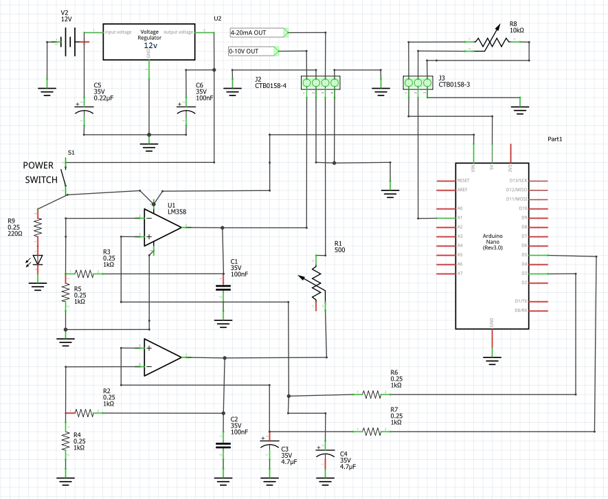
The most commonly used analog signal in Industrial Controls is the 4-20mA analog signal. This "protocol" is commonly used in industrial automation and process control systems. It represents a continuous electrical current signal where 4mA typically corresponds to the lowest possible measurement or signal value , and 20mA represents the highest value. For example 4mA might represent 0 bar pressure and 20mA would represent 16 bar.

The 4-20mA current loop is used so commonly because of the advantages it offers, such as noise immunity and long-distance transmission capabilities, making it ideal for industrial environments where electronic noise is common. Factories often have tons of inverter driven motors and fluorescent lights.

The 4-20mA signal from the sensors, instruments and transmitters is sent to receiving devices (usually hard wired) such as programmable logic controllers (PLCs) or Trip Amplifiers and the signal is used to control the Industrial Process. For example, if the pressure is below 8 bar the sensor would have a 8mA current loop. The PLC program would then turn on a pump when the pressure in below this threshold and turn the pump off again at another threshold.

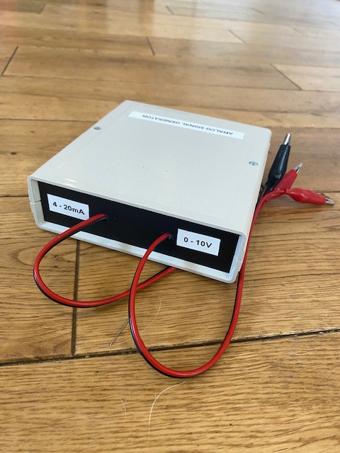
A 0-10V analog signal works the same way as a 4-20mA signal and many sensors and instruments are equipped with both protocols however some instruments only have the 0-10V protocol as it is a cheaper and easier signal to generate. For this reason you really need both a 0-10V and 4-20mA generator in your tool box if you want to reverse engineer, fault find or test industrial control systems.

The 4-20mA signal is most often preferred over voltage signals in industrial applications because even in the presence of electrical noise, the receiving PLC's and SCADA system can accurately interpret the current signal's magnitude, ensuring reliable and accurate data transmission over long distances, often several thousand metres.

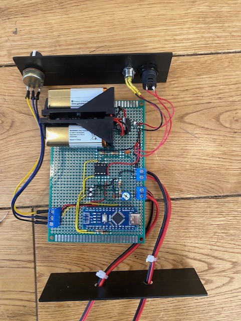
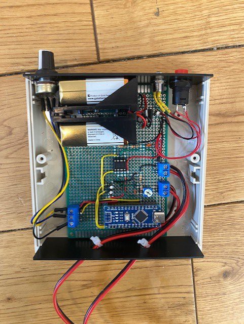
Although this device is a hand held tool the same circuit could have another use case for trialling sensors and instruments when interfacing to Industrial Control Systems. You could utilise an Arduino and the multitudes of cheap Adafruit or SparkFun sensors to try things out before committing to purchasing a $500 instrument. 

The whole project probably cost about $20 to build and 3 hours for assembly so the cost very much stands up to even the cheapest loop calibrators available on eBay or Amazon.

AnalogInPWMOutx2.ino

Code for Arduino Nano to generate the two PWM Signals

ino - 1.23 kB - 10/17/2023 at 11:06

Download

  • 2 × 9V PP3 Battery Clip
  • 1 × 9V PP3 Battery
  • 1 × LM7812 Voltage Regulator 12 Volt Regulator
  • 1 × 0.22uF Capacitor Electrolytic
  • 1 × 0.1uF Capacitor Electrolytic

View all 24 components

  • 1
    Circuit Design

    The heart of the design is the LM358 Dual Operational Amplifier (Op Amp). An Op Amp amplifies a signal and has a couple of main advantages over just using a BJT transistor as an amplifier because it has a very high input impedance (resistance) and a very low output impedance. It also has a very high gain but I'm not really using this function. I am using the Op Amp as a non-inverting amplifier with a gain of two which I will explain in an bit.

    The signal fed to the amplifier is produced by the Arduino Nano. This comes in the form of a PWM signal (Pulse Width Modulation). Pulse width modulation works by producing a square wave at a set frequency. By changing the pulse width, devices can simulate varying levels of voltage, on the Arduino the wider the width of the pulse the closer to 5V and the narrower the pulse the closer to 0V. The width of the pulse is controlled manually by turning a 10K potentiometer that is connected to an analog input (A1) on the Arduino Nano. I can't use this signal in Industrial Controls because the I need a DC 0-10V signal or a DC 4-20mA signal. The first thing I do to the signal is smooth it out with a resistor and capacitor in a low pass filter arrangement. This arrangement smooths out the PWM signal and gives a 0-5V DC signal to the OP Amp circuit.

    I am providing the Op Amp with two 0-5V signals generated by the Arduino PWM signal. One for the 0-10V output signal and one for the 4020mA Signal.

    Getting a 0-10V Signal from the Op Amp in Non-Inverting mode is easy as I simply want to double the output of the signal. When the voltage at the non-inverting amplifier input (+) is higher than the inverting input (-), the output voltage swings towards the positive supply voltage. Conversely, if the voltage at the inverting input is higher, the output swings towards the negative supply voltage. Some of the output signal is basically fed back to the amplifier to manage the gain. This feature allows the LM358 to handle signals near the supply voltage rails and does not need a negative supply. The gain of an Op Amp in non-inverting mode can be calculated with the equation Gv = R1+R2/R2. I am using 1k OHM resistors for both R1 and R2 therefore my gain is Gv = 1+1/1 = 2. I have a gain of 2 therefore my output is between 0 and 10V.

    Getting the 0-20mA signal is only slightly more complicated. I still use exactly the same set up as the 0-10V signal and still get an output of 0-10V however I then output this signal through a 500 Ohm trim potentiometer. I also modify the code on the Arduino so the PWM signal doesn't give an input voltage down to 0V I only want it going down to 1V, 2V after it's gone through the amplifier. Using Ohms law it it very simply to work out the current going through this circuit. Current (I) = Voltage (V) / Resistance (R). Therefore at 2V and 500 Ohms, I = 2/500 = 0.004A (4mA) and at 10V, I = 10/500 = 0.02A (20mA). Normally you would use 24V to drive a 4-20mA signal however using 10V is no big deal because the whole point of using a current loop instead of a voltage loop is to make the signal resistant to changes in voltage. The trim potentiometer is used instead of a fixed resistor so the output can be tuned to account for any additional resistance in the circuit.

    Below is a schematic of the circuit.

    The YouTube Video below shows on the oscilloscope how the signal changes from a PWM signal to smoothed out to 0-5VDC to the amplified to 0-10VDC.

  • 2
    Assembly

    As I mentioned in the beginning I really very much needed this signal generator as a tool to test a control circuit over a weekend and I couldn't find my commercial loop calibrator anywhere. This is why it was assembled on prototyping board using 26AWG solid hook-up wire. I find 26AWG wire works best for me in this scenario but others might prefer thicker or thinner hook wire.

    I tend to solder the lower components first then work up to the taller components. A tip I find helps is to use a bit of blue tack to hold the components in place while soldering.

    Another tip is that I use a couple of cable ties (zip ties) as strain relief on the output cables to stop any force pulling the wires from the screw terminals.

    Below are some pictures of the assembly.

  • 3
    Software

    To be honest you really don't need a microcontroller for this project and you could easily use a couple of 555 Timers or 556 Timers to generate the PWM. It might actually work better because the PWM can then be at a higher frequency giving a smoother DC output when using the low pass filter.

    I had a Arduino Nano in my parts bin so I just used it with a little bit of code to generate the PWM signal.

    The code is below and in the files section.

    /*
    For Full project description go to https://hackaday.io/project/193211-diy-industrial-controls-analog-signal-generator
    */
    
    const int analogInPin = A1;  // Analog input pin that the potentiometer is attached to
    const int analogOutPin = 3; // Analog output pin that the LED is attached to
    const int mAOutPin = 5; // Analog output pin that the LED is attached to
    
    int sensorValue = 0;        // value read from the pot
    int outputValue = 0;        // value output to the PWM (analog out)
    int mAOut = 0;
    
    void setup() {
      // initialize serial communications at 9600 bps:
      Serial.begin(9600);
    }
    
    void loop() {
      // read the analog in value:
      sensorValue = analogRead(analogInPin);
      // map it to the range of the analog out:
      outputValue = map(sensorValue, 0, 1023, 0, 255);
      mAOut = map(sensorValue, 0, 1023, 50, 255);
      // change the analog out value:
      analogWrite(analogOutPin, outputValue);
      analogWrite(mAOutPin, mAOut);
    
      // print the results to the Serial Monitor:
      Serial.print("sensor = ");
      Serial.print(sensorValue);
      Serial.print("\t output = ");
      Serial.println(mAOut);
    
      // wait 2 milliseconds before the next loop for the analog-to-digital
      // converter to settle after the last reading:
      delay(2);
    }

View all 4 instructions

Enjoy this project?

Share

Discussions

Tom Goff wrote 10/17/2023 at 12:54 point

As a final note to this project I actually found my commercial signal generator the afternoon after a built this one. It was hiding under a drum of cable that I needed to move just before I did some home decoration I promised my partner I would do.... 

  Are you sure? yes | no

Dan Maloney wrote 10/18/2023 at 00:22 point

Of _course_ you found it after you built the circuit! Glad you built it, though -- interesting stuff. Wrote it up for the blog, should publish soon.

Love some of the other stuff I saw on your Twitter feed. Hope you post here on Hackaday.io more -- we'd love to see your builds!

  Are you sure? yes | no

Similar Projects

Does this project spark your interest?

Become a member to follow this project and never miss any updates