 niko
nikoHi, want to start this project saying, the main purpose of this project is to learn to connect and program different sensors, im going to do it nowadays, i know there must be thousands similar projects, but this will not be a reason to stop making my own approach.
This means that i want to share it with everybody as i sourced it and learned from other people guides, and im making it with their help, so what i do with their help should help others.
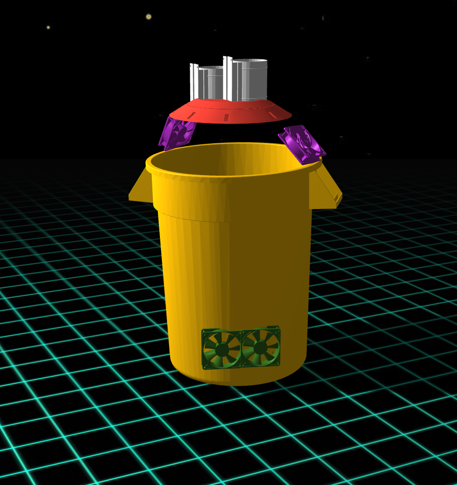
#First objectives of the Program:
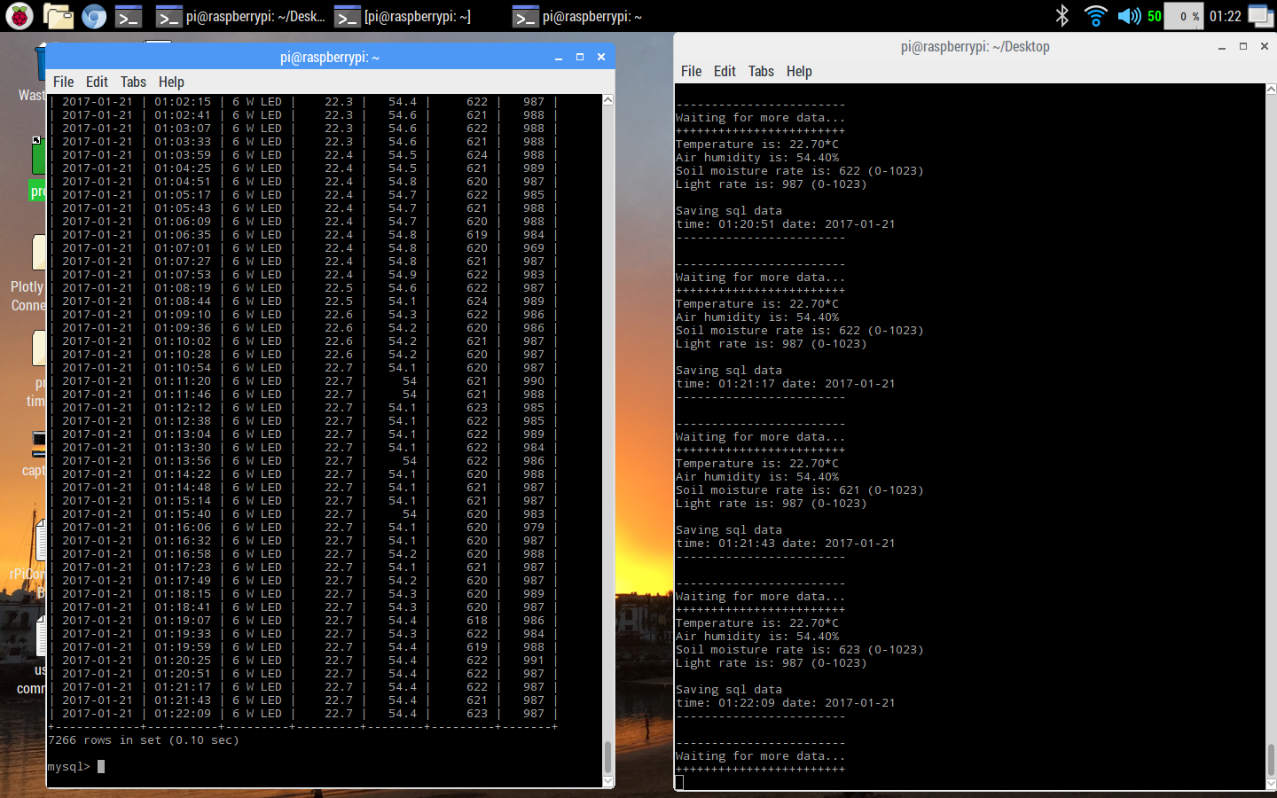
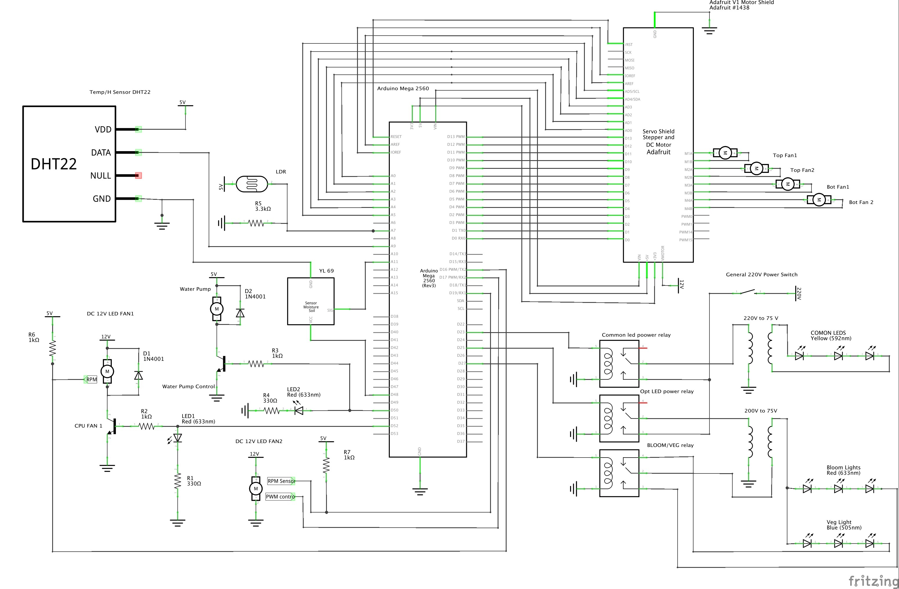
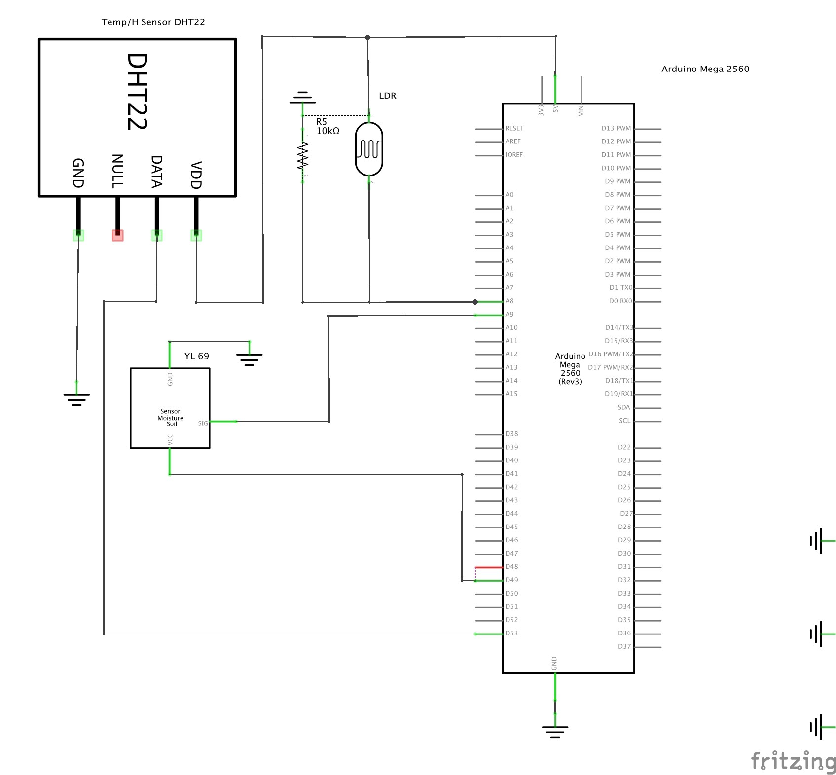
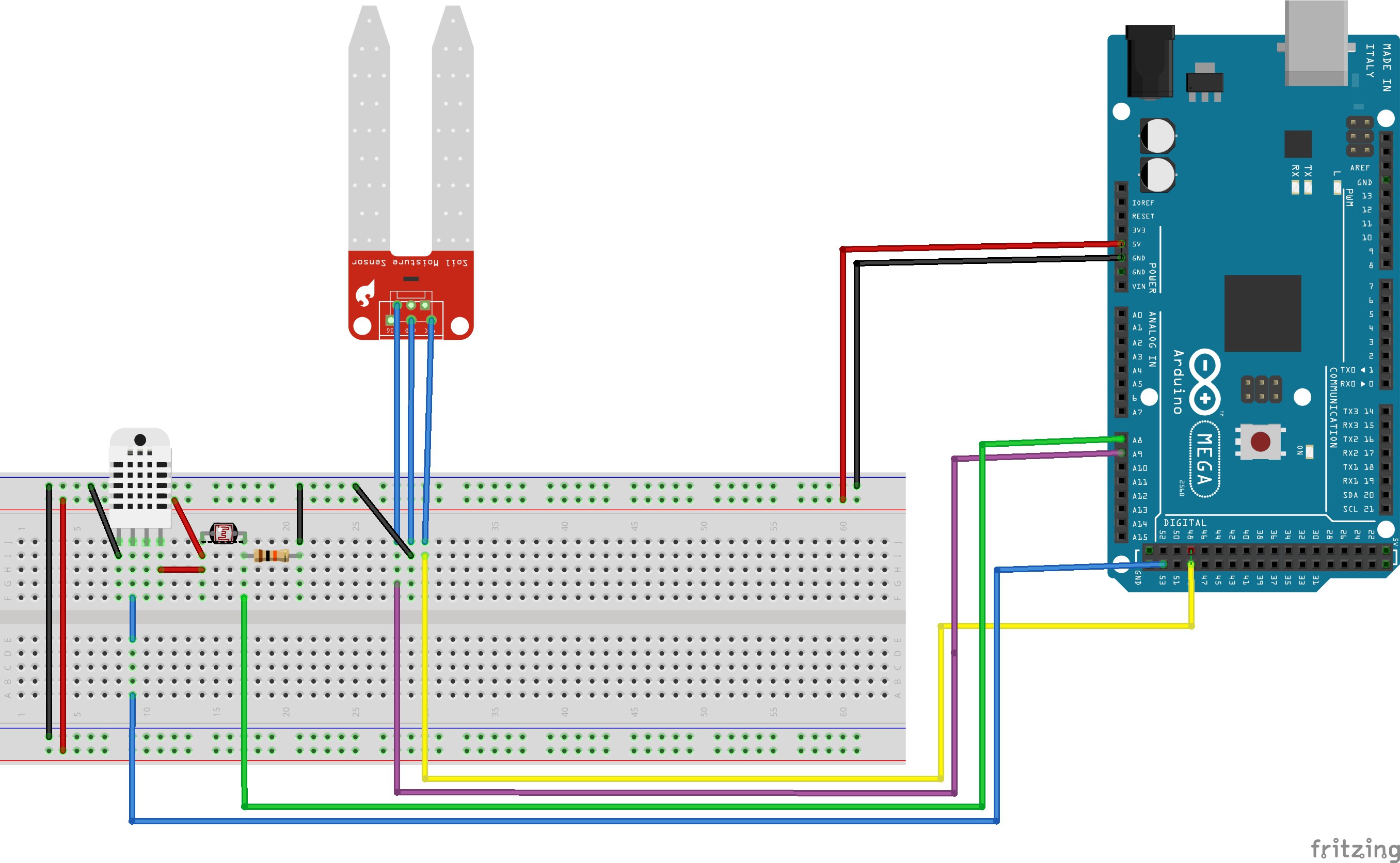
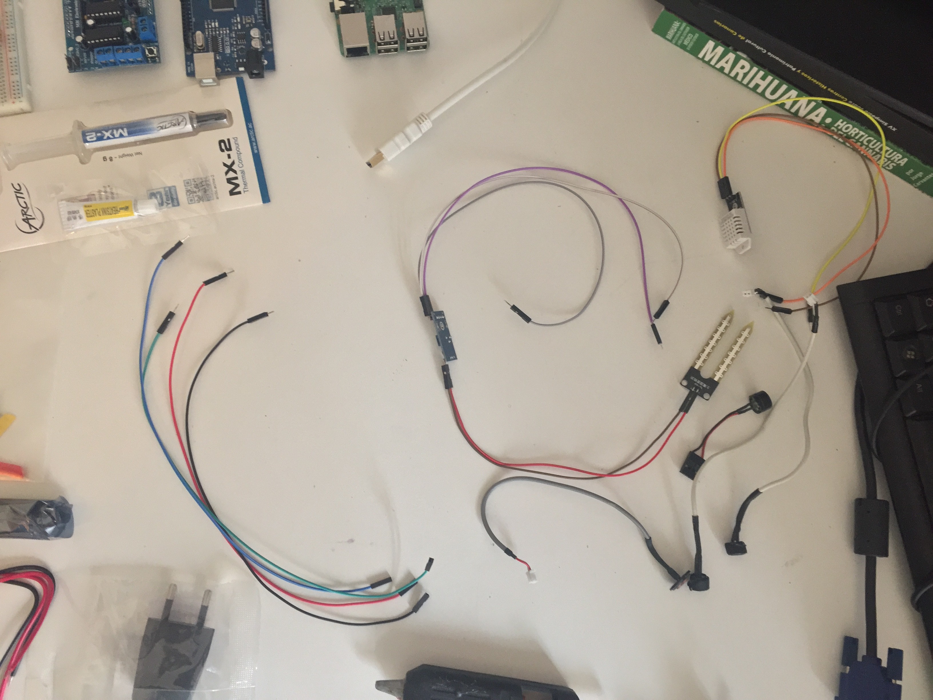
-Meter Humidity and temp from air
-Meter Humidity Soil
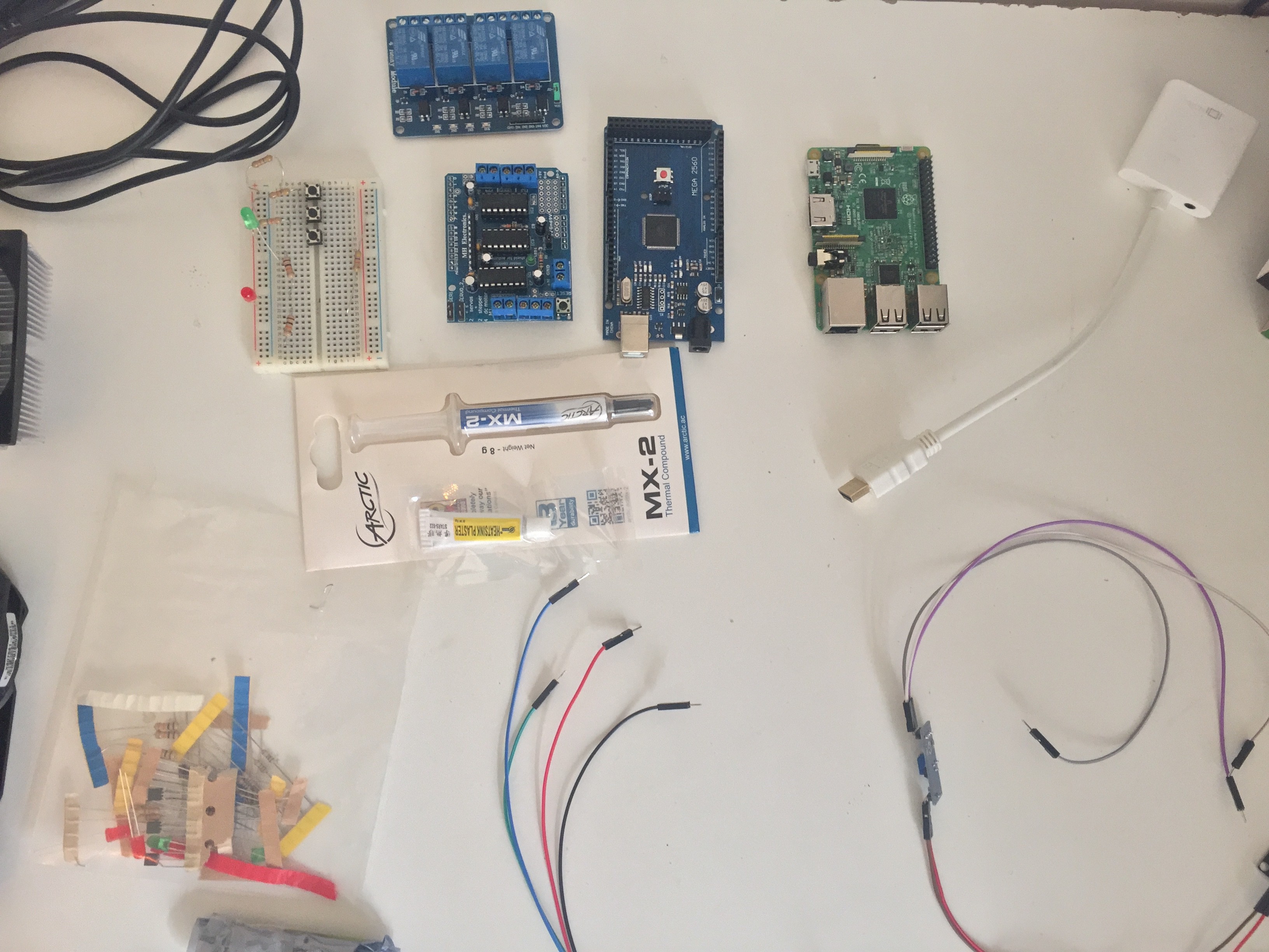
-Meter amount of light (LDR)
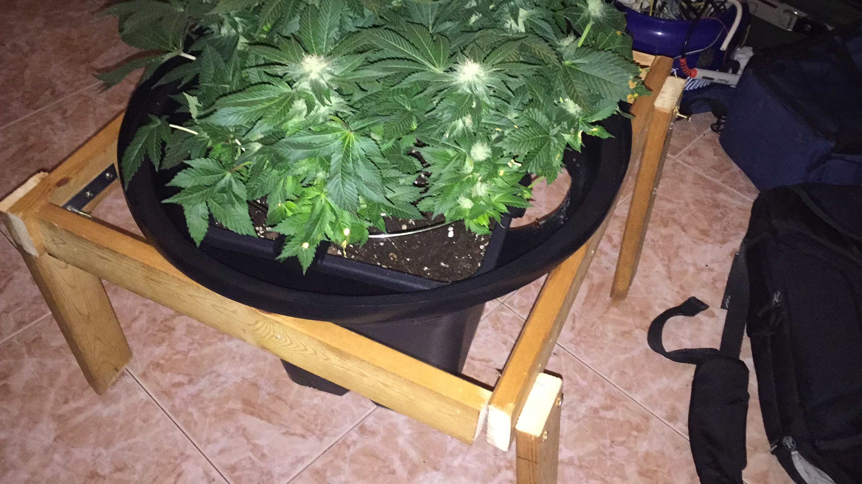
-Water the plant when needed
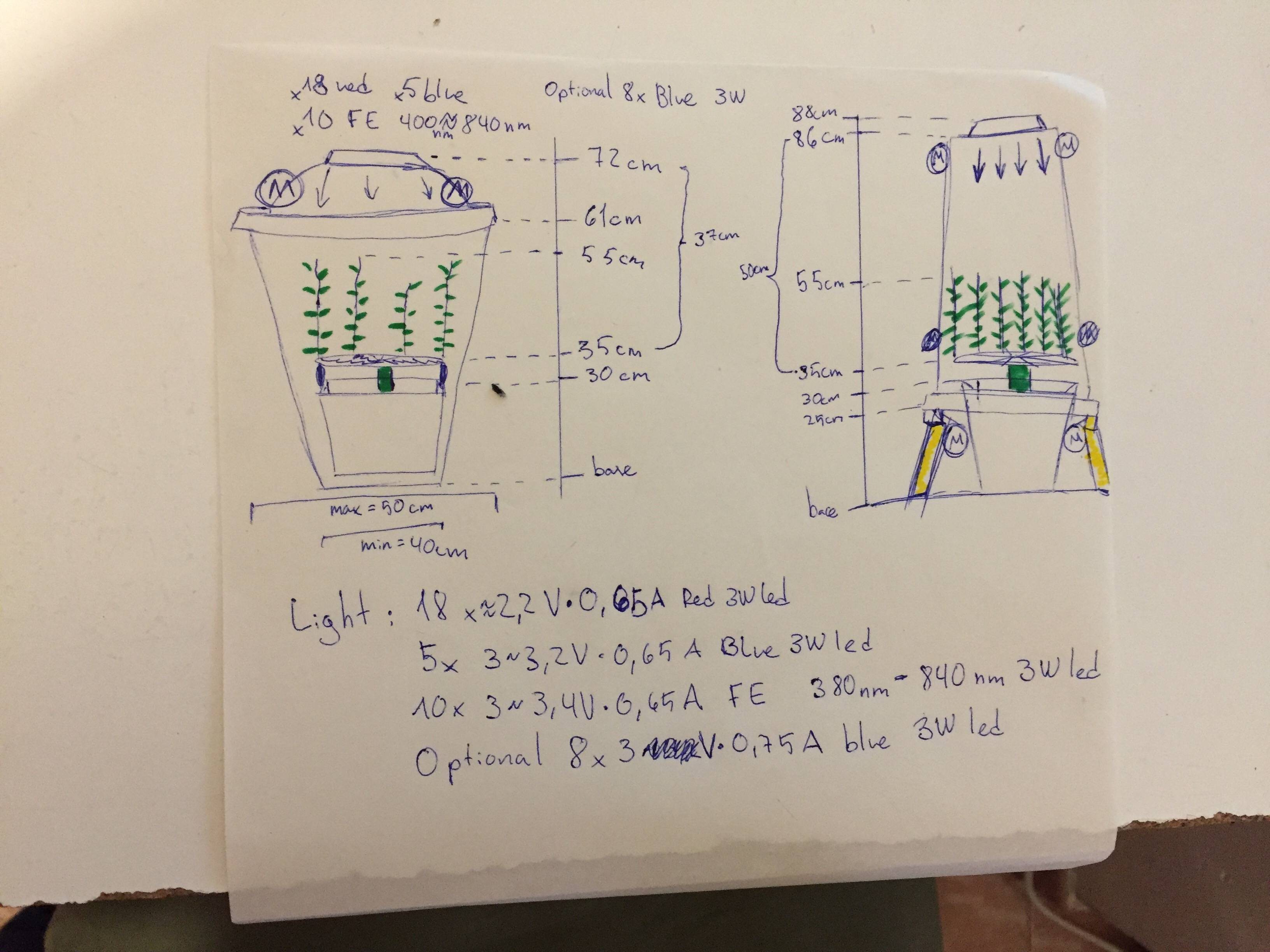
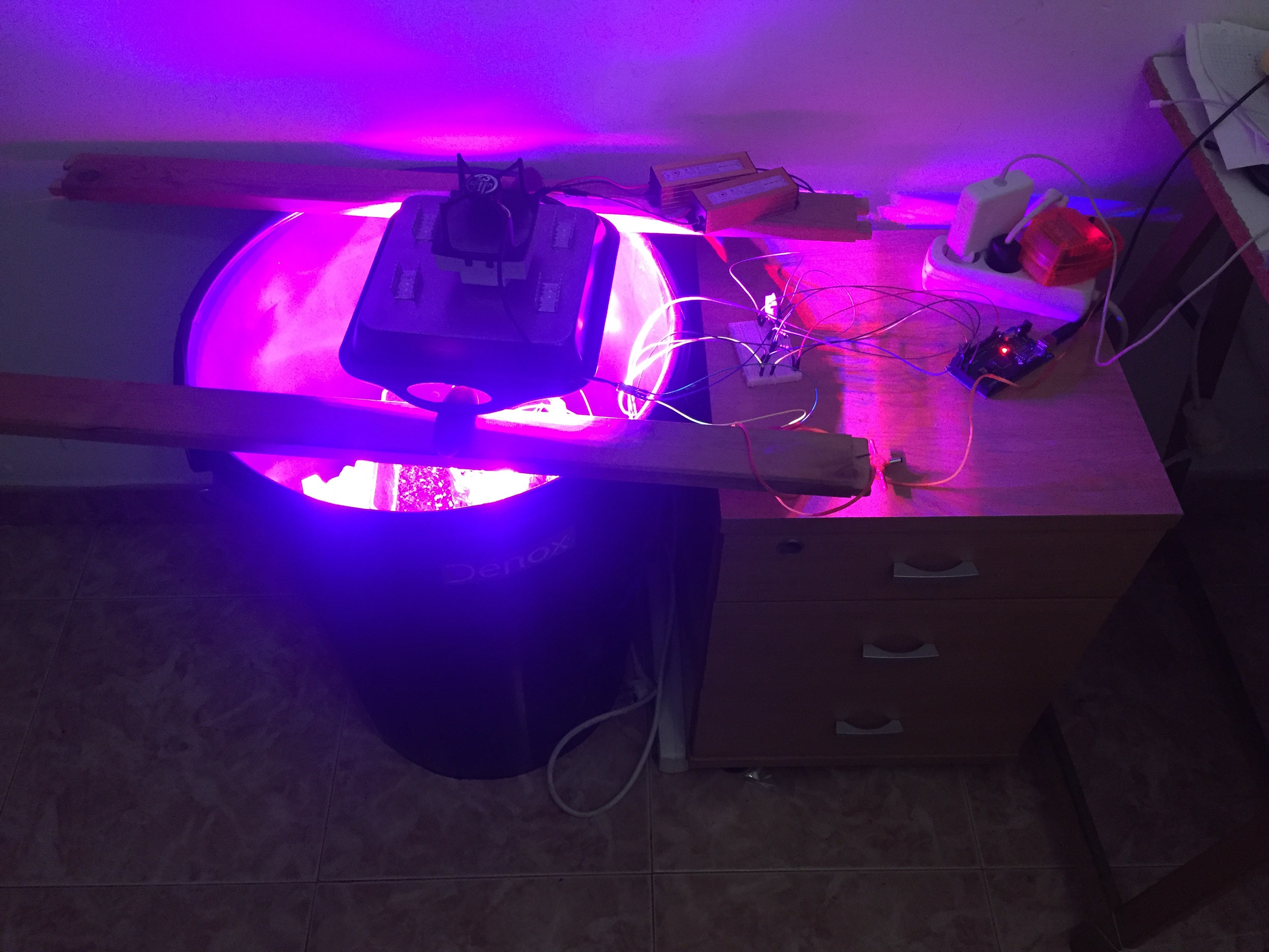
-Control the lightning cycles
-Control the light spectrum using led arrays
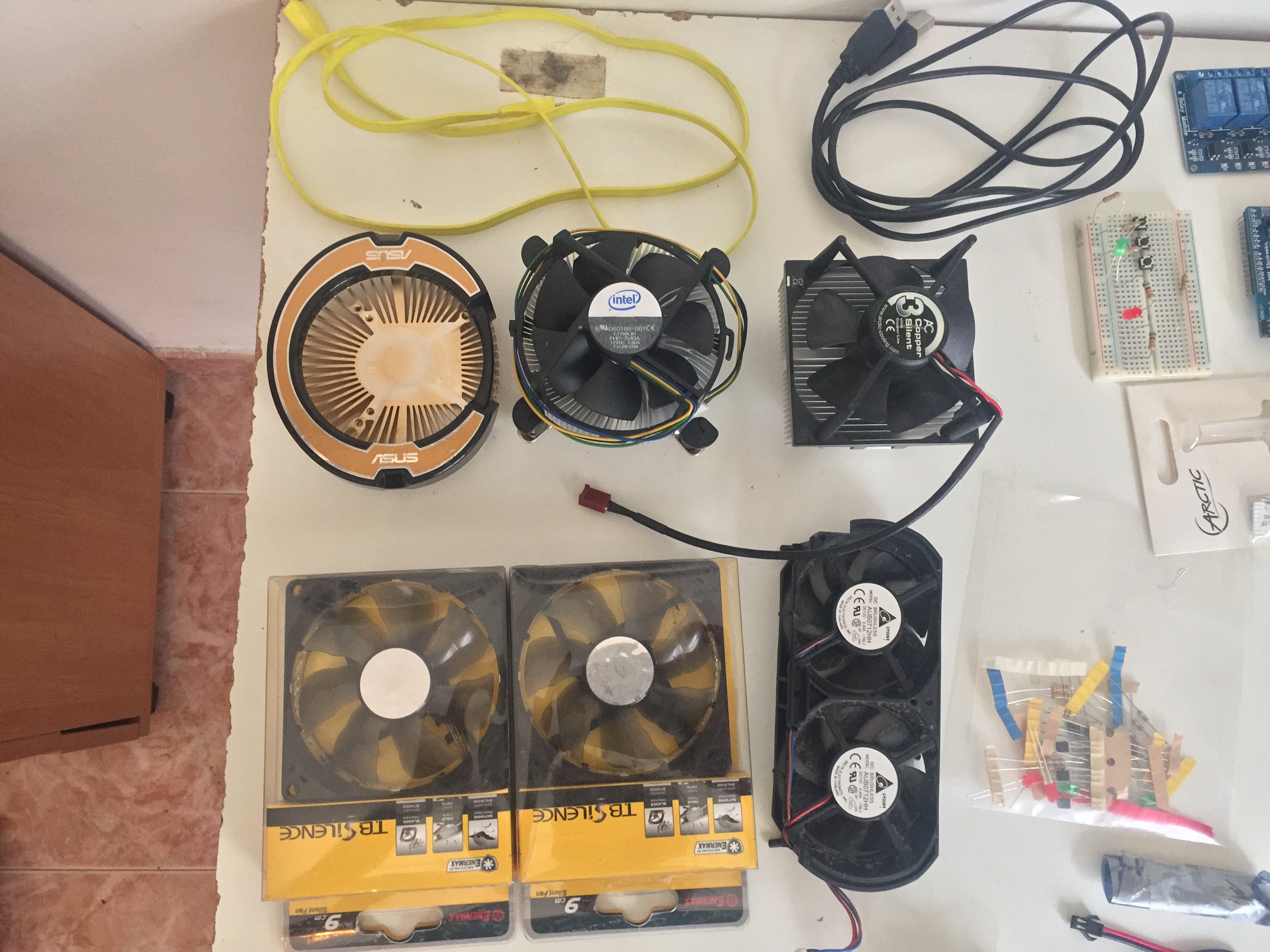
-Extract and intake air when needed and have control over the fans Speed, RPM
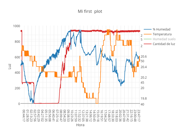
-Collect data from arduino to a Rpi and control variables from there
#Later Features (Any good suggestions would be welcome)
-Change all the power supplies to just a old sauvage pc power supply
-Control over single led/ small amount of them (Better lightning control) using MOSFET and using 12V pc power supply ramp
-Control of CO inside of the bucket (improved climate control)
-Control of the Rpi by web
-Better control of the light (change LDR for more precise stuff)
-Control of the temp at the led heatsink
-Control of plant height by sensors
-Control of light distance to maximize lightbeam
-Webcam
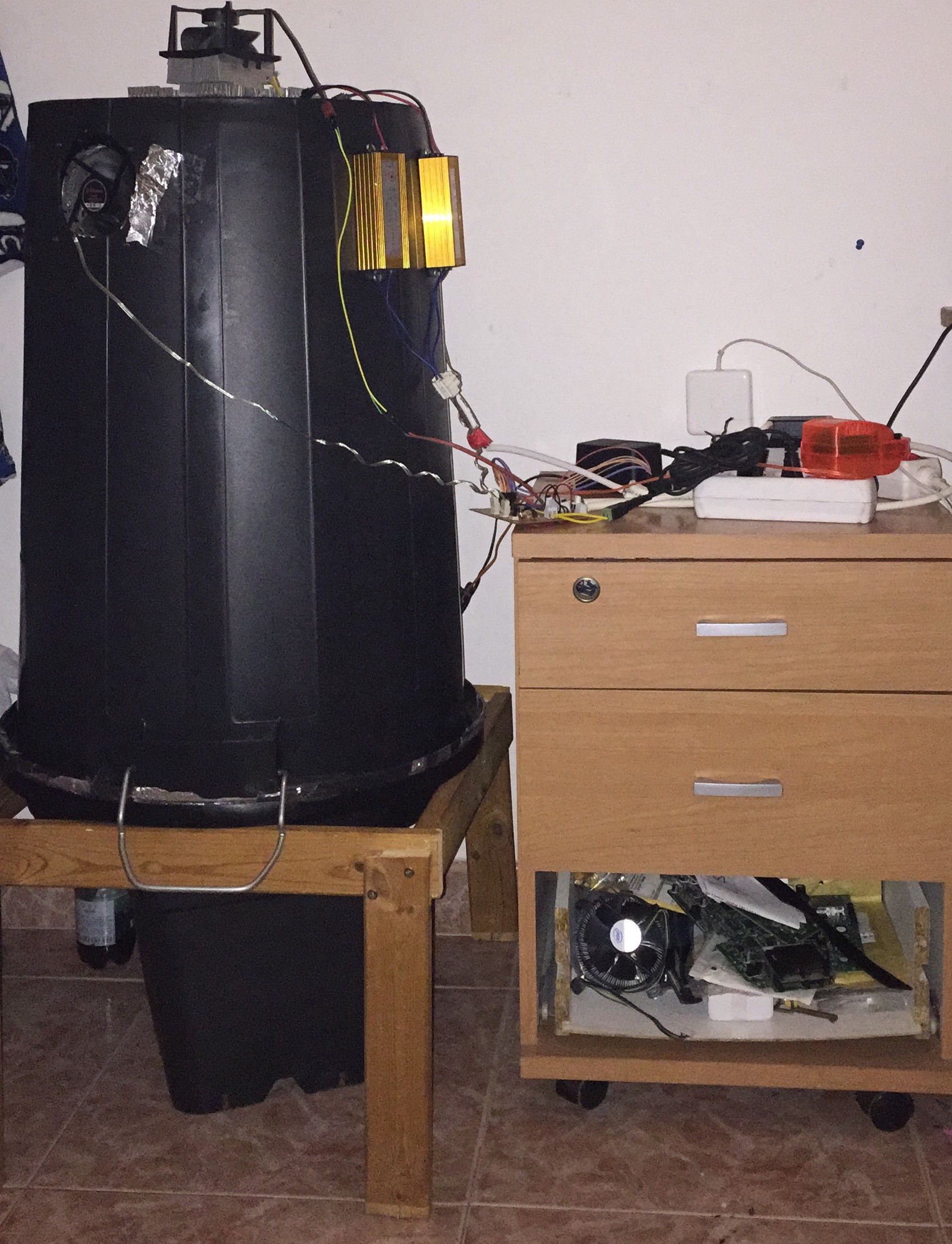
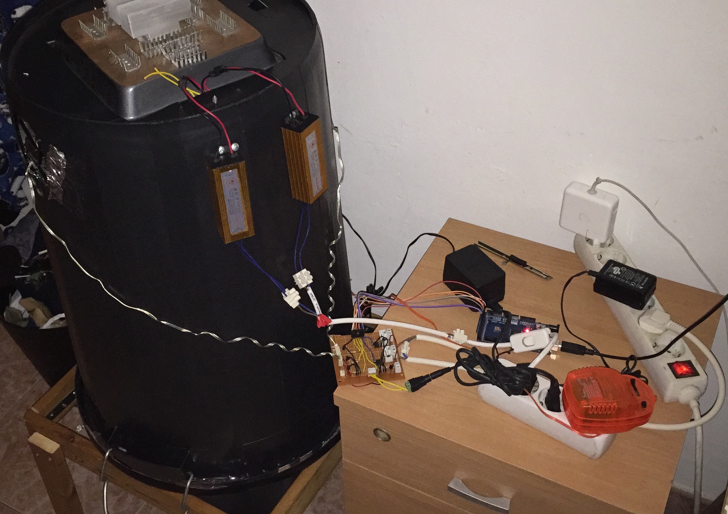
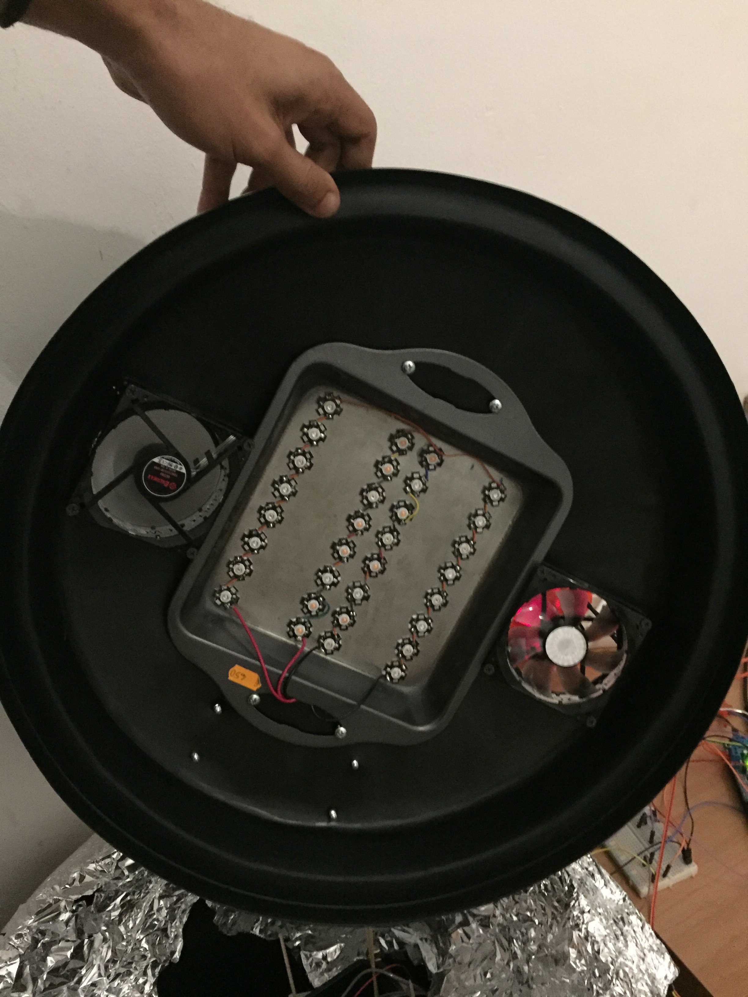
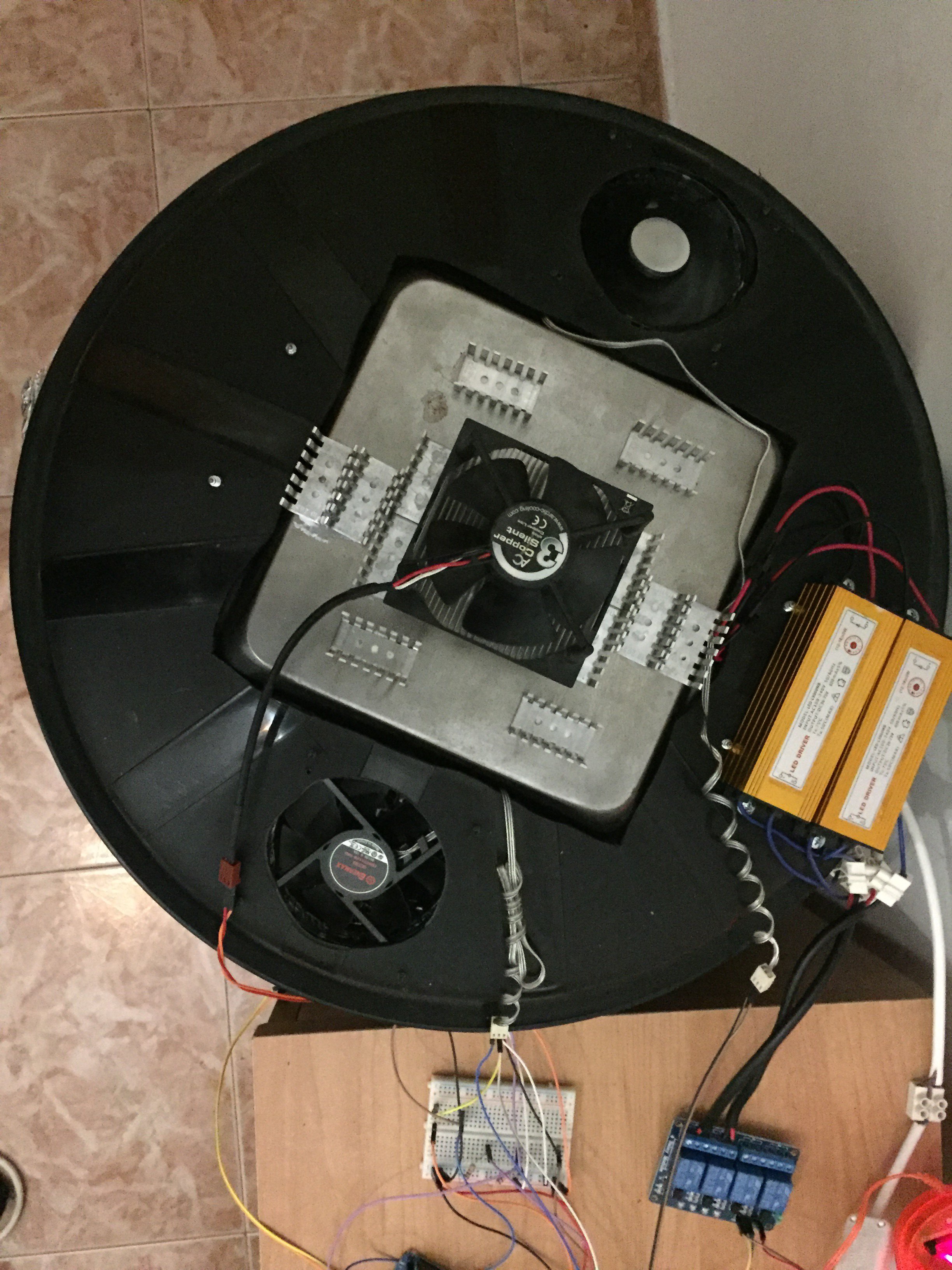
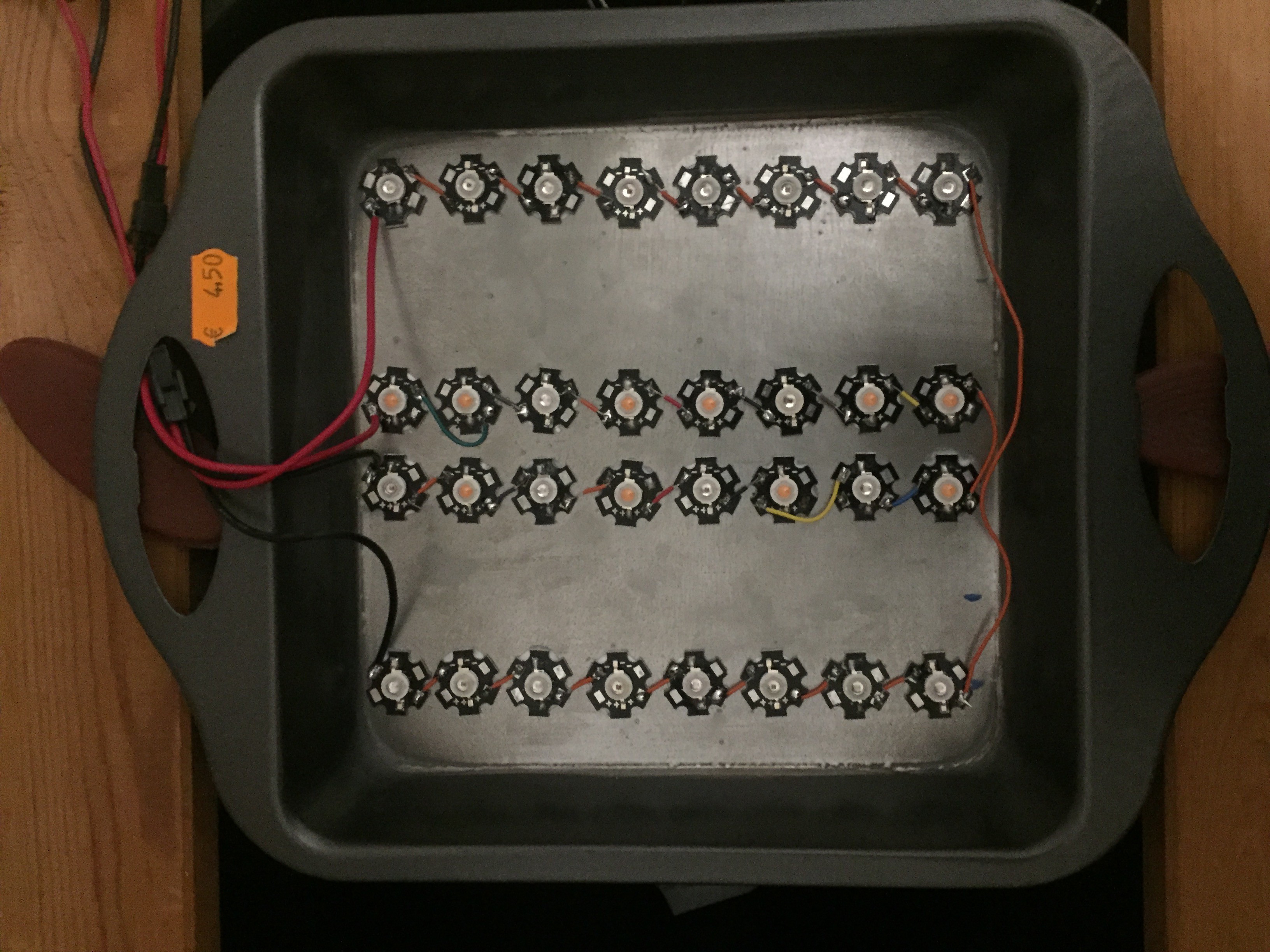
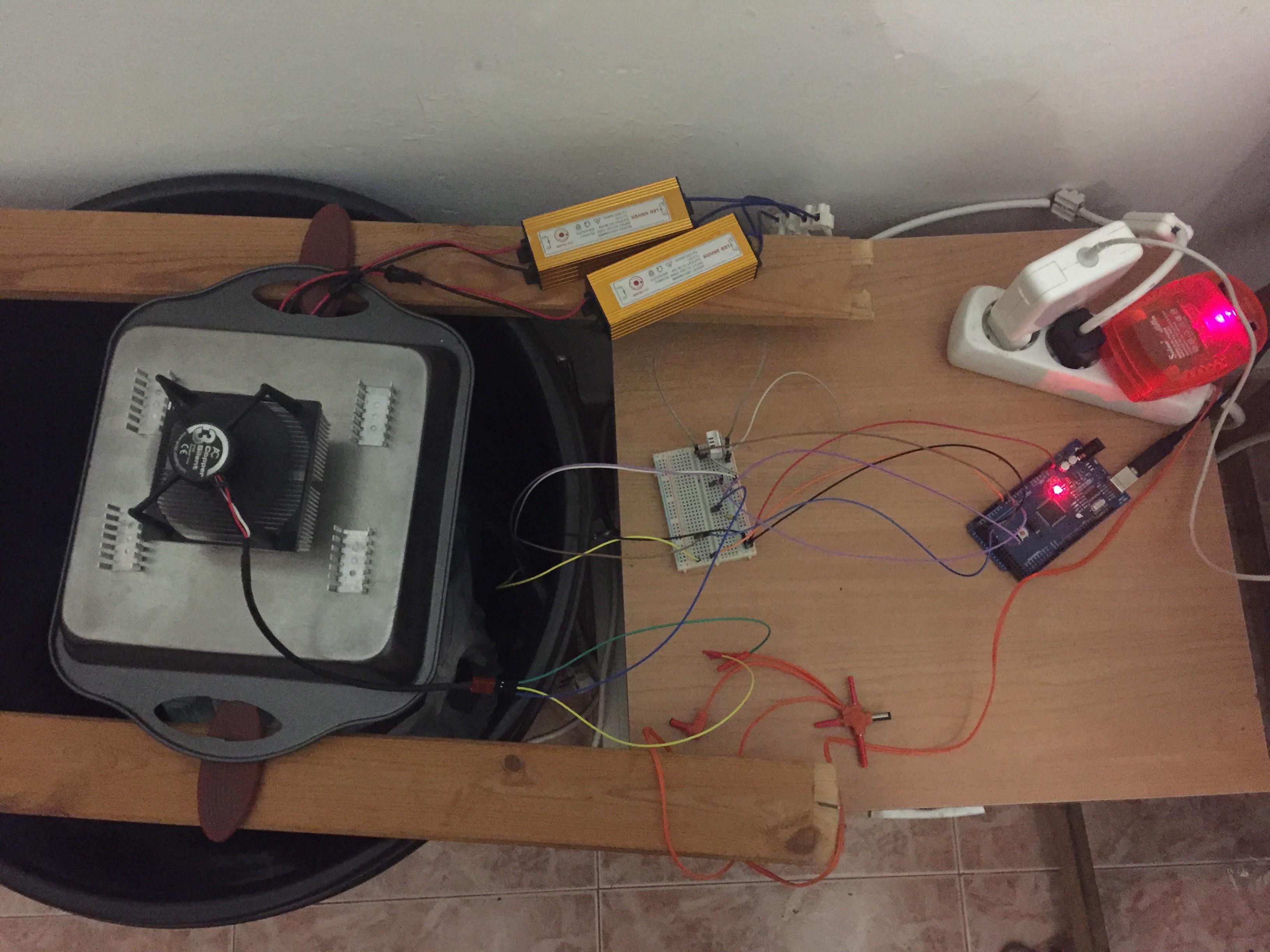
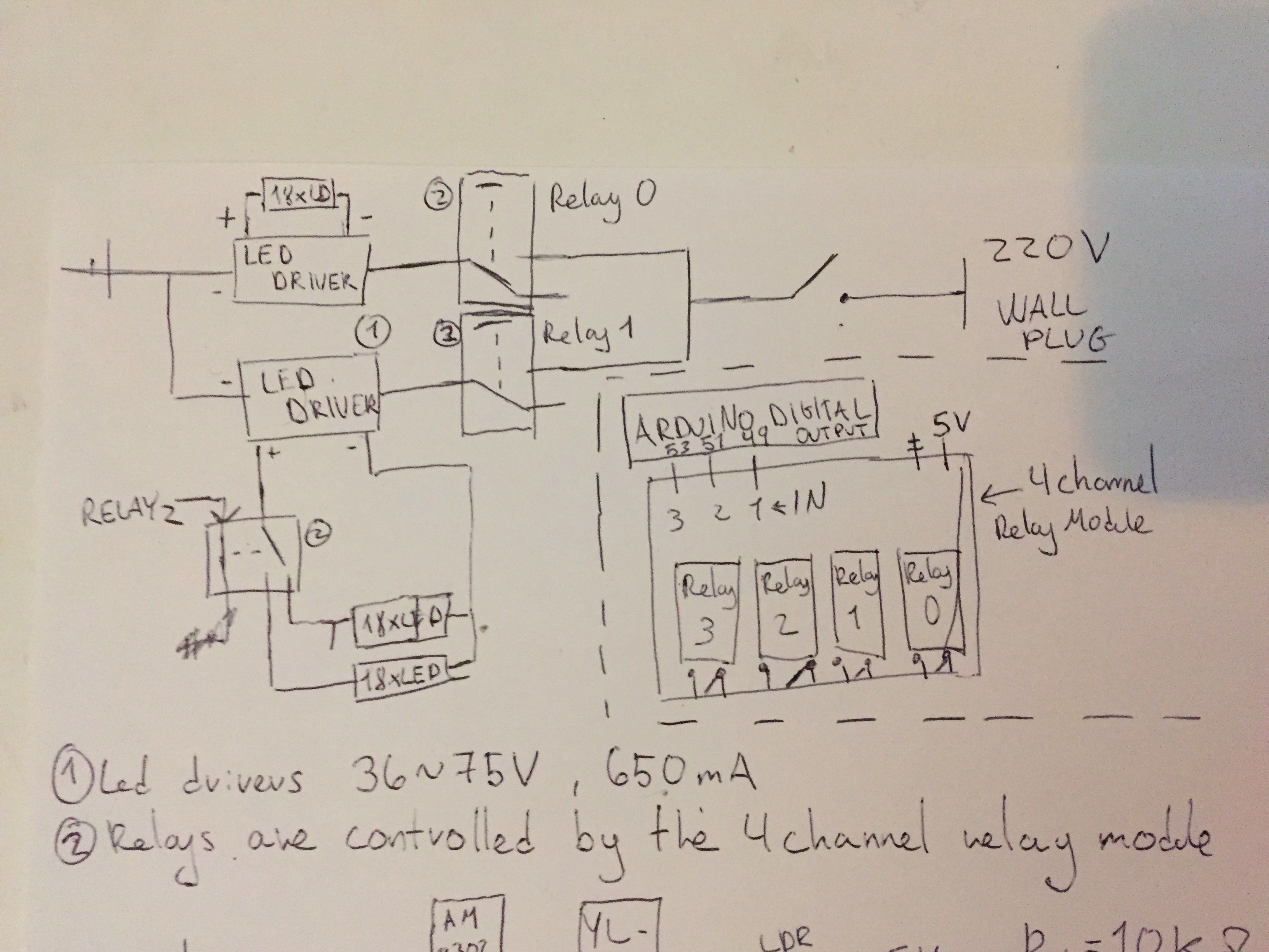
 ##Led Drivers and 3W leds:
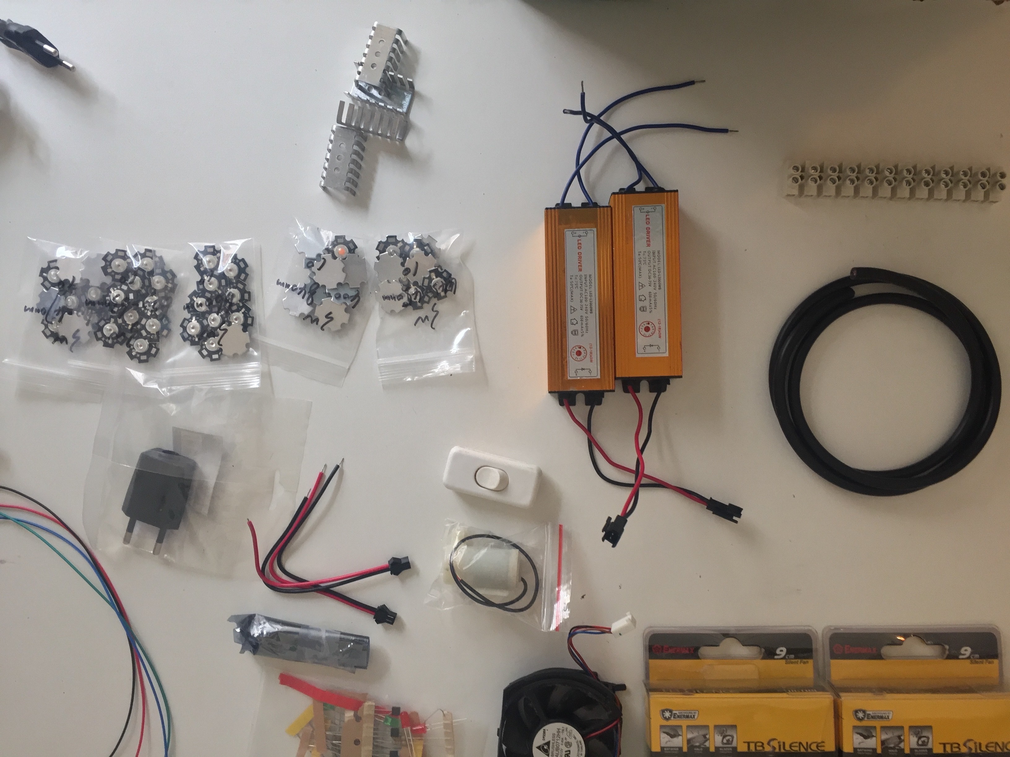
 ElectroBoy
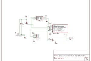
 Thomas Snow
 Jason
Jason
 Dan Tudose