 Tim
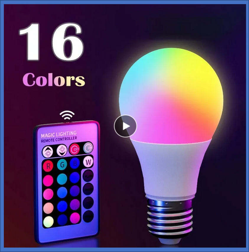
TimThis isn't a high-tech Wifi, Bluetooth, or Zigbee light bulb but one that's operated with an IR remote control. I purchased it for approximately $2, including shipping. The functionality is straightforward: you can choose from sixteen colors and there are several flashy animation options. However, the dimming function appeared ineffective. I wasn't too impressed with its brightness and felt the colors appeared washed out.
Remote control
The remote control looks like those accompanying many gadgets from China, indicating a highly costomizable design. I was impressed by its cost-optimized construction.
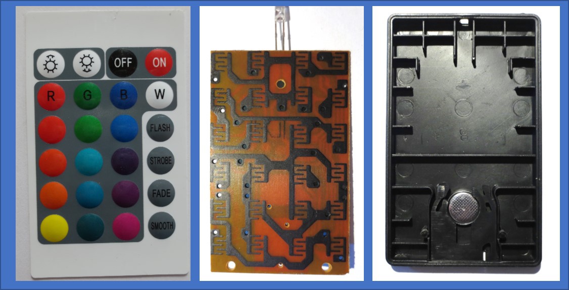
The remote control comprises three components (from right to left):
- A molded backplate that also houses the battery.
- A PCB with circuits on one side and button contacts on the other.
- A key foil with embossed keys, designed to make contact with the button contacts when pressed
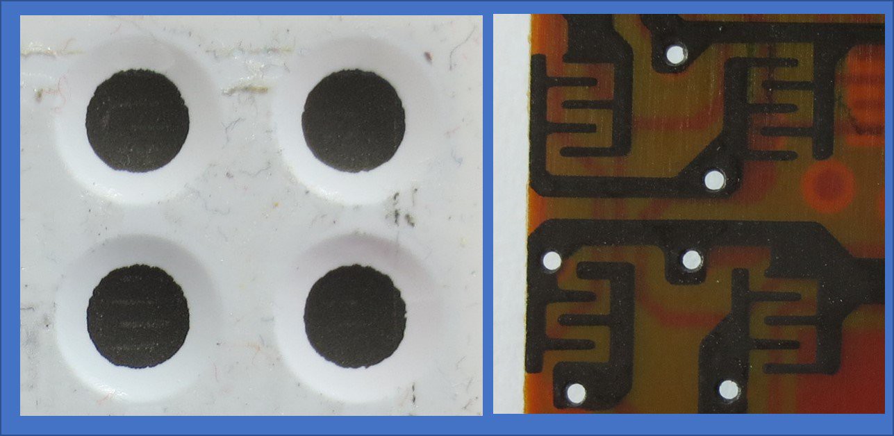
Details of the keys can be seen above. The rear of the key foil is coated with conductive ink (possibly carbon-based) and doesn't touch the PCB in its resting state due to the foil's embossing. When a key is pressed, it establishes contact with the corresponding button contact on the PCB. The PCB itself is coated with patterned conductive ink . This coating is likely carbon-based and was probably applied through screen printing.
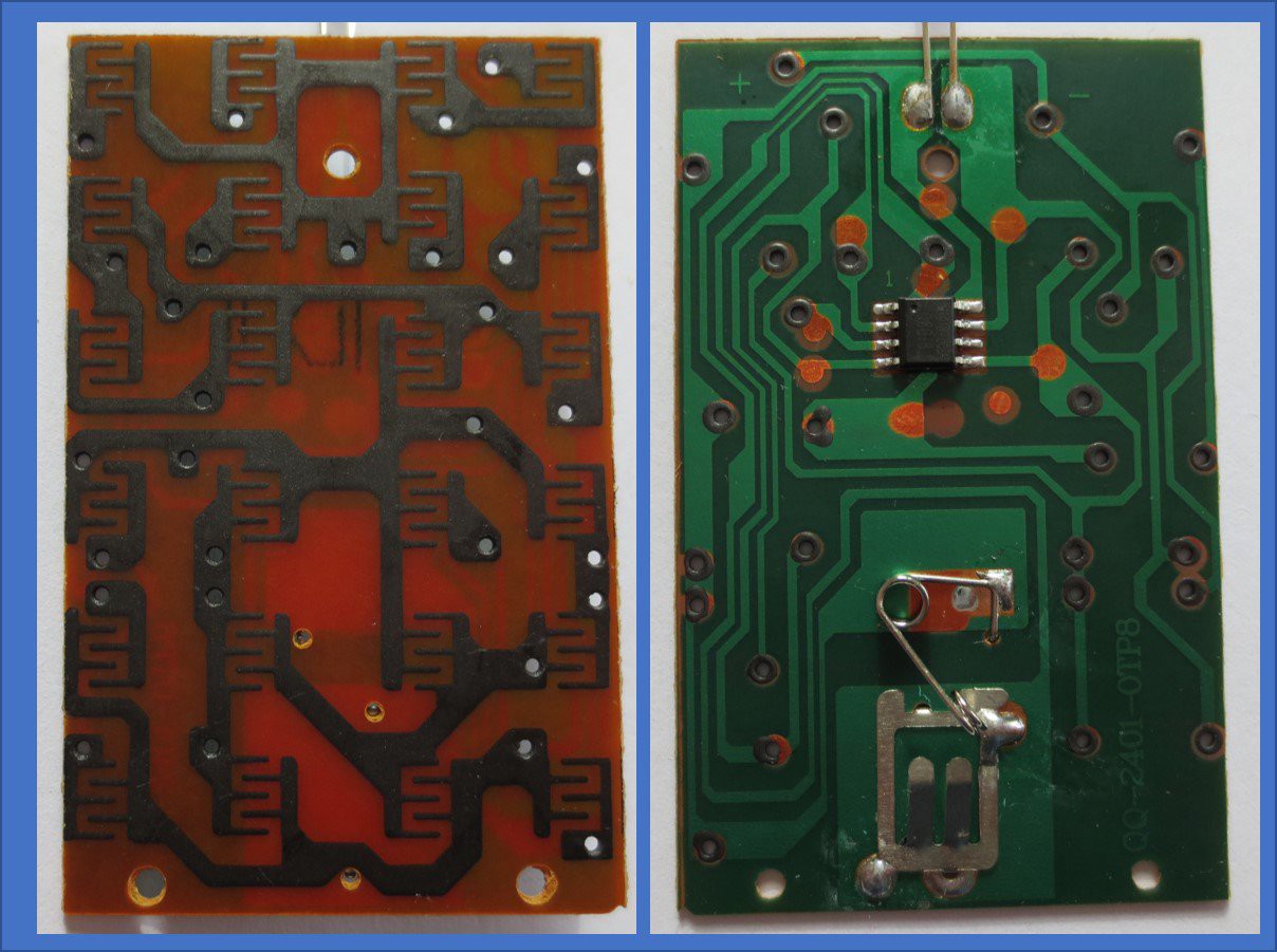
Both sides of the PCB are depicted above. The rear side features a typical copper trace PCB with solder resist, which connects to the carbon-ink through through-hole layers. What's particularly noticeable is the minimal number of components: there's a single SOIC8 IC, the infrared LED, and a battery holder.
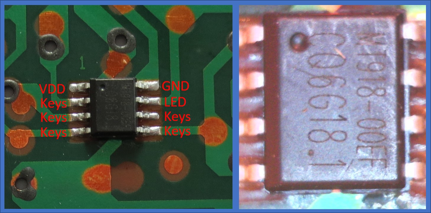
Details of the MCU are shown above. Based on the power supply pin locations, it looks like one of the ubiquitous ultra-low-cost 8bit MCUs - for example a PIC clone or Padauk MCU. Suprisingly, it does even have part marking: MT918. I have not been able to ID the supplier, though.
What is remarkable is the ability to read out 20 keys using only five pins without extra components. A matrix design would have demanded 5+4=9 I/Os. Charlieplexing would allow control over 20 keys with 5 I/Os (since n2−n=25−5=20n2−n=25−5=20) but necessitates additional diodes.
So, what's the mechanism? Initially, I hypothesized that the carbon traces might form resistive voltage dividers with an ADC for readout. While plausible, the likely inconsistent contact resistance of the switch to the pads suggests a more digital solution.
Examining the traces, it seems some keys connect to GND, others to VDD, and the rest between the key sensing pins. With five I/Os, this permits encoding 5 keys for GND, 5 for VDD, and 10 for combinations between the pins (binomial coefficient "5 choose 2" = 5! / (3! * 2!) = 10). This totals 20 keys.
The infrared LED (IRED) current is defined the GPIO driving capacity, not the nicest solution but not without precedence. I presume standard 36kHz pulse coding is employed for the IRED, demanding a fairly accurate oscillator in the MCU, likely adjusted during programming. The MCU is probably programmed directly on the PCB via the test pads.
In summary, it's a highly simplified solution, comprising just the essential components to function.
Light Bulb
The semi-transparent dome can be easily detached from the light bulb, revealing a single PCB.
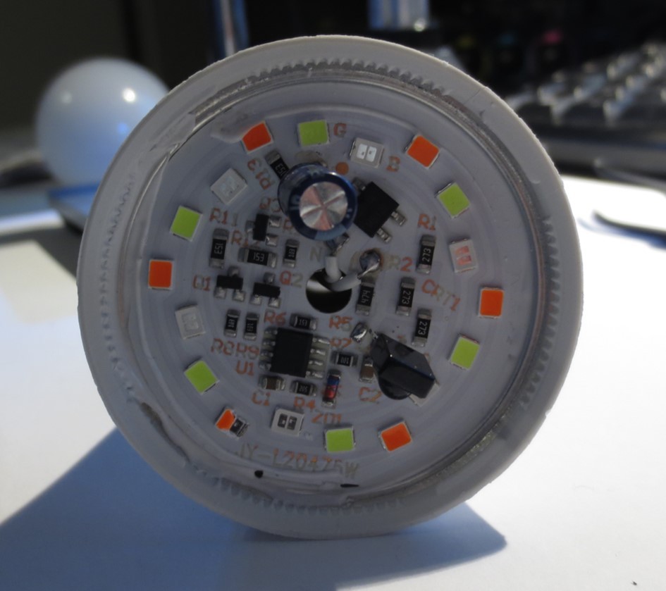
A detailed view of the PCB after its removal from the lamp socket base, although, unfortunately, some of the components were damaged in the process.
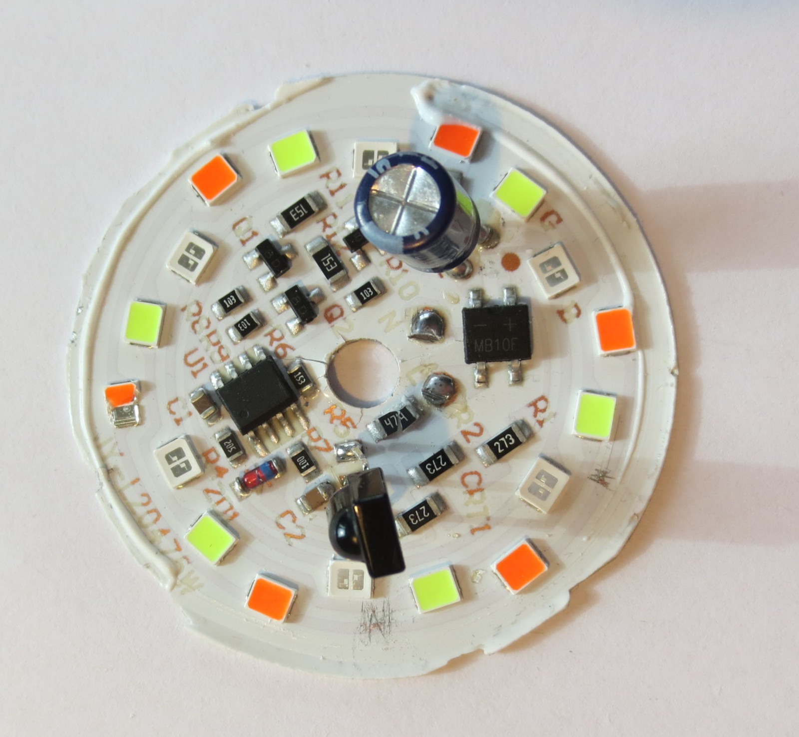
The PCB is single sided with an aluminum core. What can we see?
- There's a bridge rectifier (MB10F) that rectifies the mains current, which is 240V in this instance.
- Another SOIC8 microcontroller, unmarked this time, manages all operations.
- An IR remote control receiver is present, which receives the remote control signal.
- The supply voltage for both the MCU and the remote control receiver is stabilized using a zener diode (ZD1). Current is restrained by a resistor. It's intriguing that no LDO was employed, but perhaps the advantage of a zener diode is enhanced voltage stability, while typical LDOs can handle only a few tens of volts as input. Additional resistors and capacitors ensure current limitation and voltage stabilization.
- There appear to be three LED strings for red, green, and blue lighting. Each string seems to be regulated (switched on and off) by a transistor. Resistors provide current limitation, and a 2.2µF capacitor helps mitigate the inevitable 100Hz ripple. The LEDs' dimming is achieved via pulse width modulation (PWM).
Everything is, again, implemented with a bare minimum of components.
LEDs
The LEDs used here are actually quite curious and are key to being able to simplify the circuit is much as it is. The first notable thing is that the blue LED are clear, while the green and red LED appear colorful.
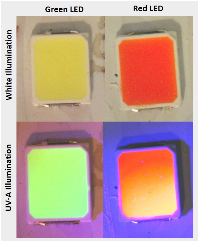
The reason for this is that all LEDs utilize blue-emitting LED chips. The green and red LEDs employ phosphors to convert this blue light into green and red hues, respectively. As illustrated in the image above, the phosphor emits light when exposed to UV-A (as seen in the bottom row).
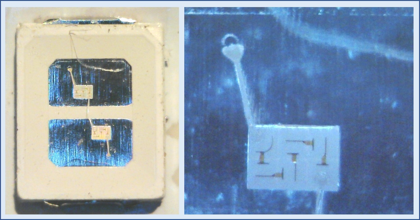
Taking a closer look at the blue LEDs reveals that each LED package actually containts two LED dies that are connected in series. The right side of the image shows a magnification of a single die - these are actually high-voltage LED dies where a number of LEDs is connected in series on a single die! (Nice youtube video explaining those).
Indeed, I had to apply more than 31 V to get one of these LEDs to emit light. This implies that the total voltage drop across a string of 6 LEDs exceeds 186V. Given that all LEDs are based on the same blue-emitting chips, the same voltage drop occurs across the red, green, or blue string.
This high voltage enables the LEDs to be powered directly from the rectified mains voltage, bypassing the need for more complex inductance-based voltage converters.
Conclusions
In conclusion, while the utility of the RGB light bulb may be limited, it is a fairly nice example of low-cost electronic optimization based on purposefully tailored components.
Discussions
Become a Hackaday.io Member
Create an account to leave a comment. Already have an account? Log In.