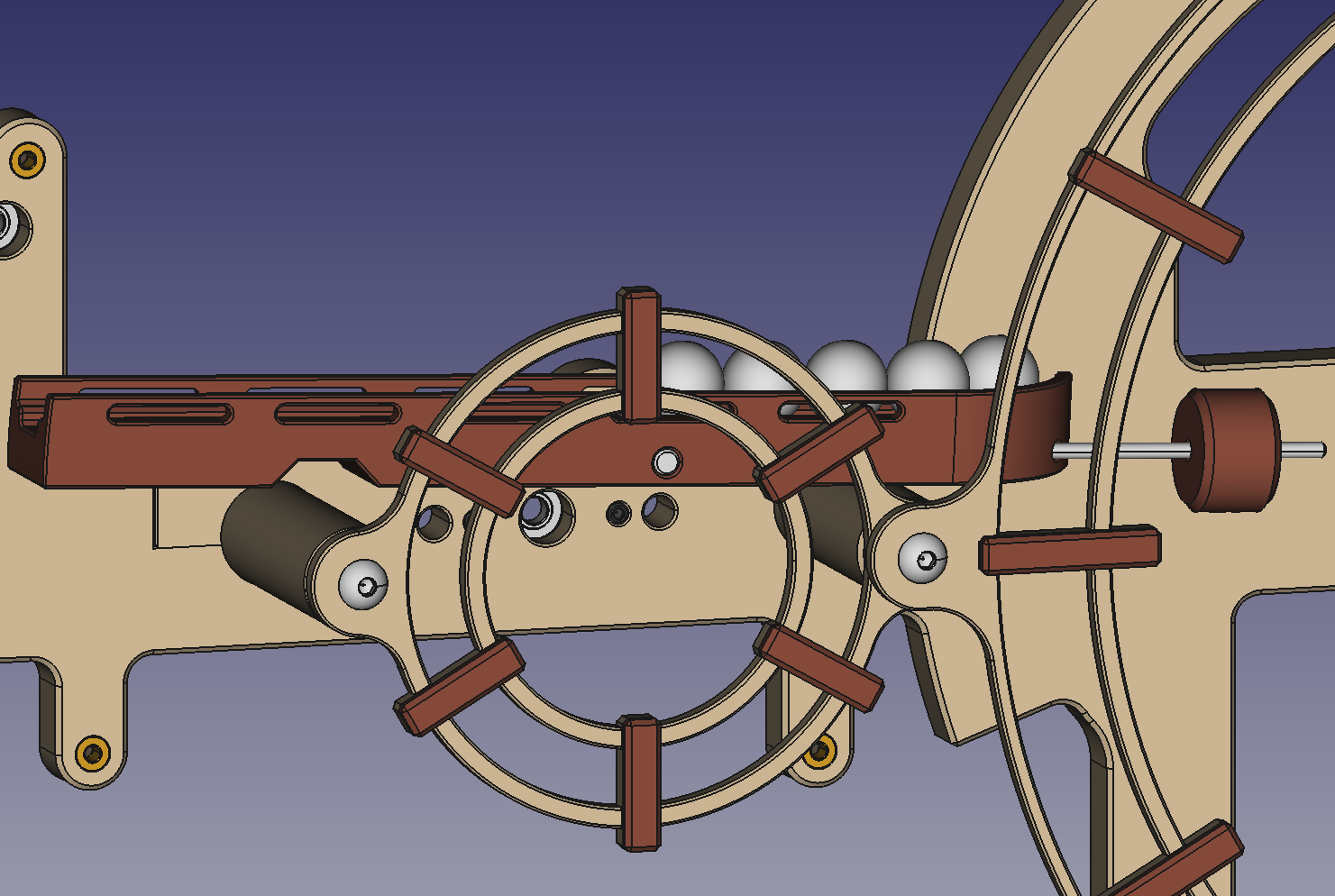
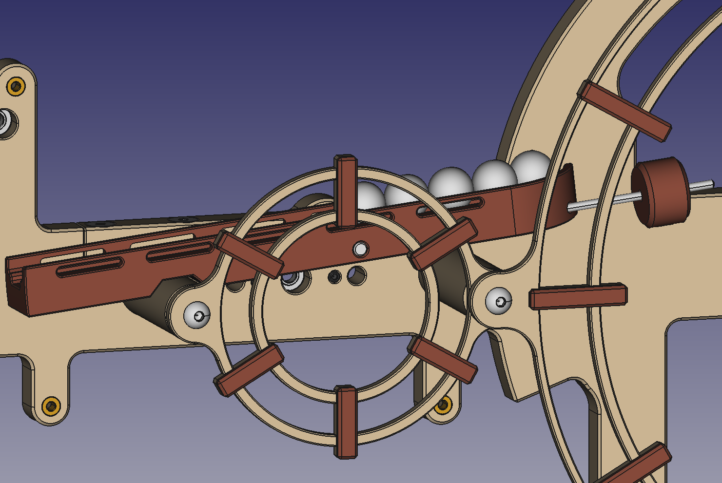
How the clock is supposed to work was made pretty clear from the videos that I found on YouTube. The whole mechanism is keyed off from the marble lift wheel that make one revolution per hour.
- As the wheel goes around it will pick up one marble from the bottom marble storage ramp ( in the slightly offset lead hole). Then the wheel will pick up all the marbles in the upper teeter totter accumulator ramp in sequence into the outer holes as they rotate past the ramp.
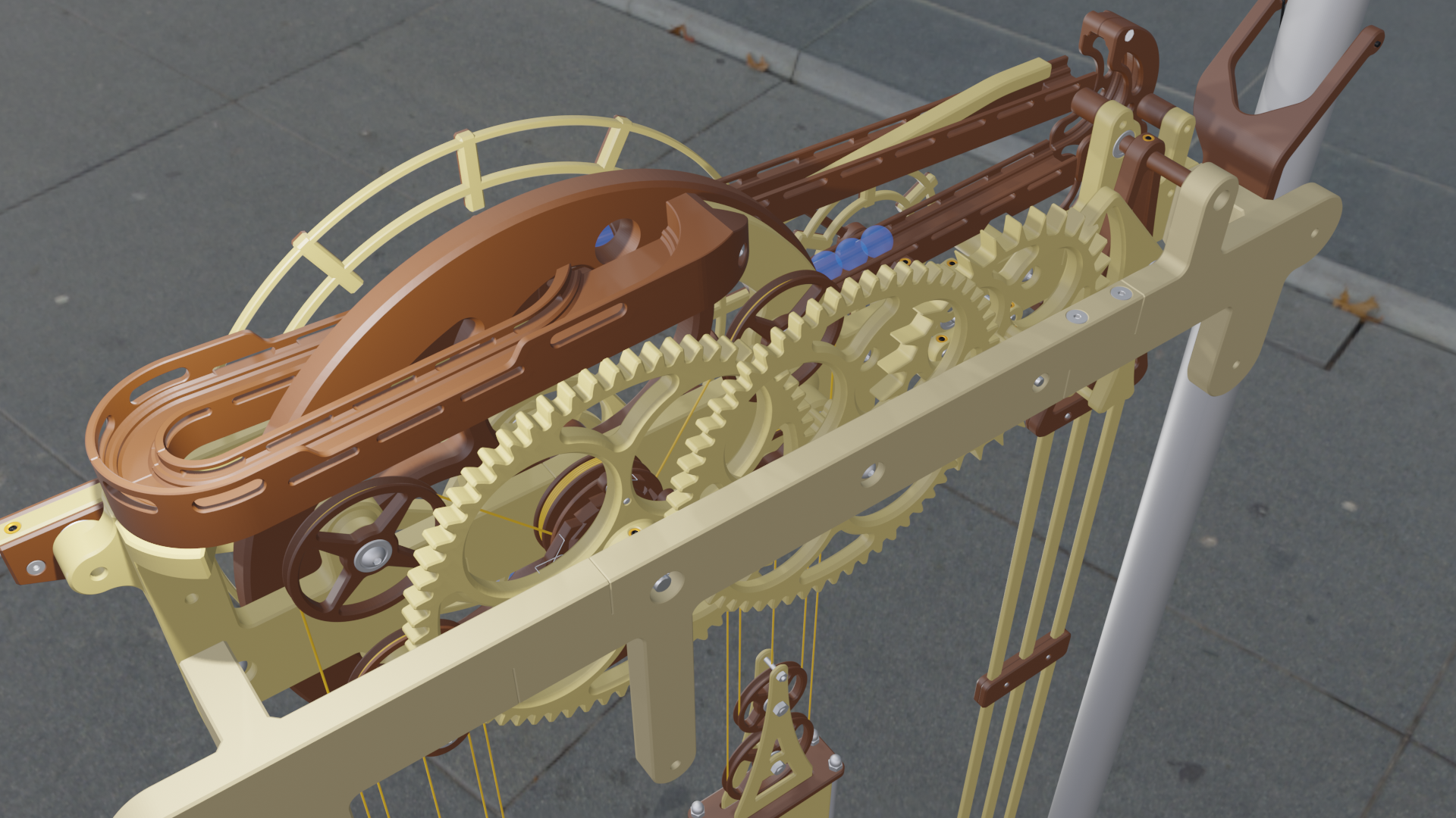
- As the holes in the lift wheel reach the top the marbles are allowed to exit onto a ramp at the back. The marbles roll down and around the ramp to stack up in the front of the clock at the trip arm's marble stop.
- As the minute hand approaches the 12 o'clock position, the cam follower on the trip arm is activated so that the marble stop on the trip arm allows a marble past to be held back by the secondary stop on the trip arm.
- When the minute hand reaches the 12 o'clock position, the trip arm cam follower is allowed to reset, letting the advanced marble proceed down the ramp and restraining the rest of the marbles in the train.
- As the released marble rolls down the ramp it will again depress the trip arm to allow the next marble to be advanced to the secondary stop position.
- When the marble exits the ramp it will ring the gong and release the advanced marble to proceed down the ramp to continue the eventual release of all the marbles in the train. The length and angle of the ramp greats the delay between the striking of the gong.
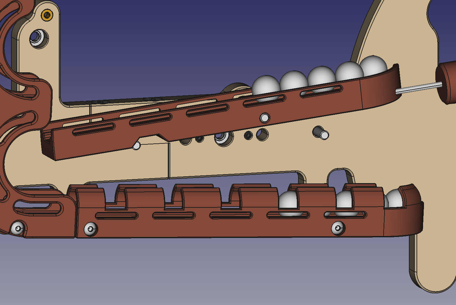
- After each marble triggers a gong strike it is directed into the upper teeter totter accumulator ramp. The teeter totter is balance so that it remains angled down towards the lift wheel until the 12th marble is added to the teeter totter.
- When the 12th marble is added the teeter totter tips over to release all 12 accumulated marbles to be directed to the bottom storage ramp, thus restarting the process for the next 12 hours.
Tipping ramps are used in a lot of marble kinetic sculptures, but combining it with the lift wheel creates a mechanical adder/accumulator with a reset.
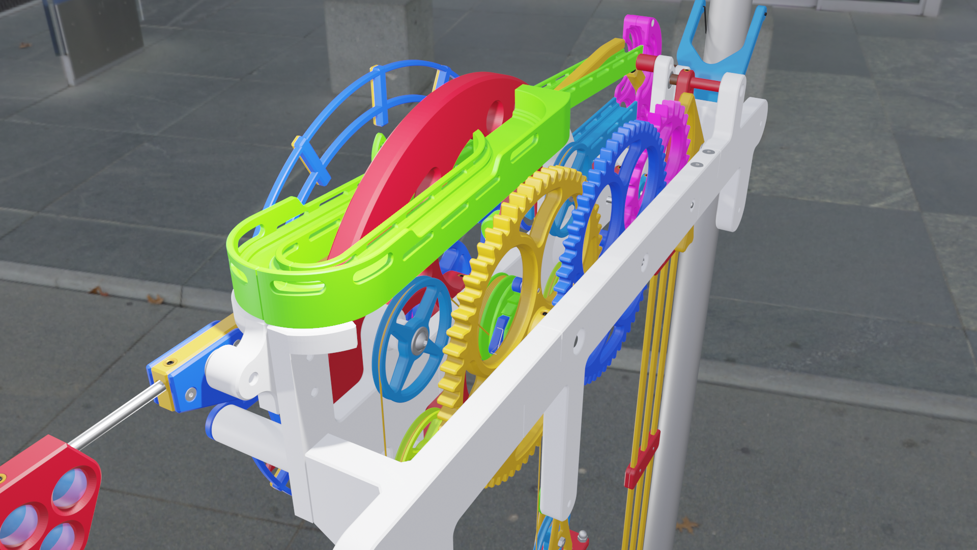
The time keeping portion off the clock is regulated by a 1 meter (1 second) pendulum and a Graham Yoke escape wheel with 30 teeth, resulting in one revolution of the escape wheel per minute. A drive train reduces the escape wheel's revolutions by 60 to rotate the lift wheel (and the minute hand) once per hour. A second 12 to 1 drive train hangs off the axle off the lift wheel to reduce its revolutions to once per 12 hours for the hour hand. The second drive train is free hanging and uses a weight to keep it vertical.
Simple huh?
I just needed to create a version that could be 3D printed, not to difficult right?
Time to fire up FreeCAD.
You can find the all the FreeCAD files on GRABCAD.
Armed with the marble size (16mm) and the printer bed size (300x300mm) I set about designing the clock. After iterating through various design choices I've come up with a design that I think has a good chance of working, I just need to print out a few test pieces to see if my design choices will work. Most notably the Graham Escapement, the Teeter Totter rail, and the marble lift.
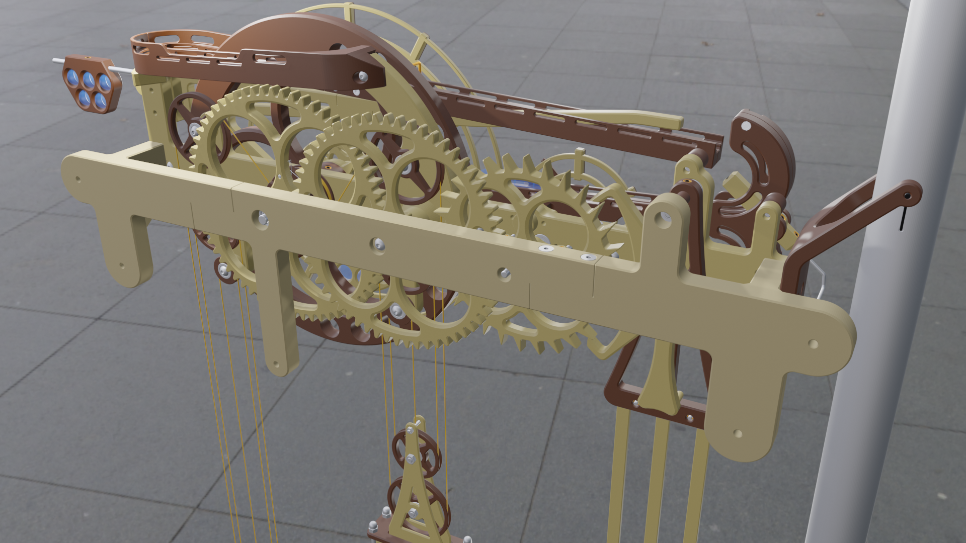
Over all the design uses 5mm axles and flanged F695 bearing for the pivot points except for the lift wheel which uses an 8mm axle and 608 bearings. M3, M4, and M5 thermal inserts along with appropriate screws are used to fasten the various pieces together. Parts were designed to be printed with minimal or no supports (I really don't like using printing supports unless I have to).
A few of the more interesting design elements are as follows:
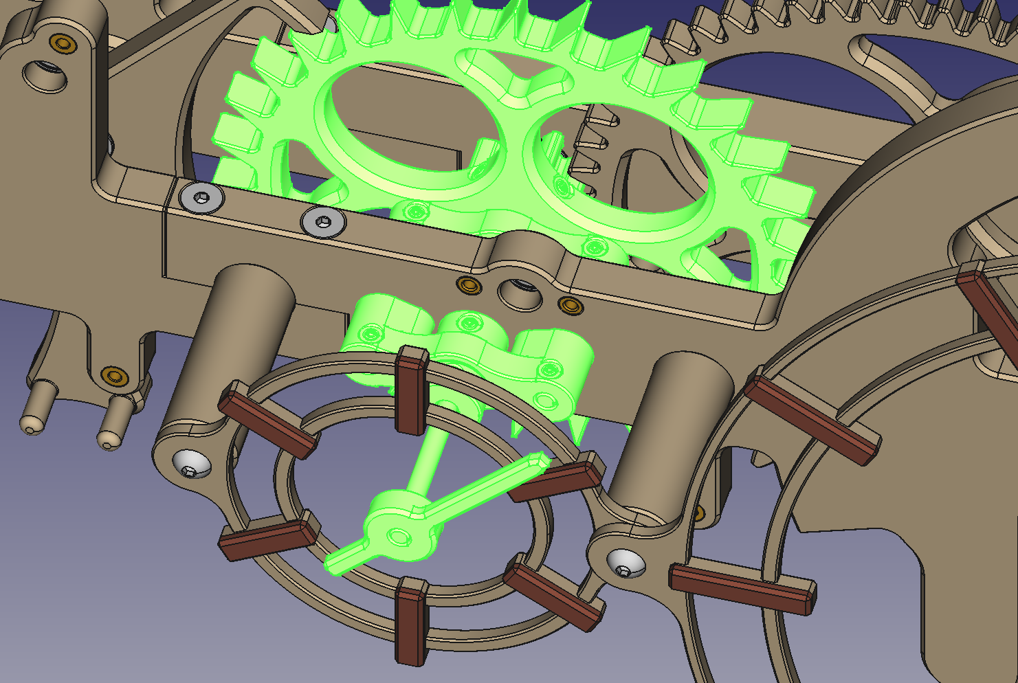
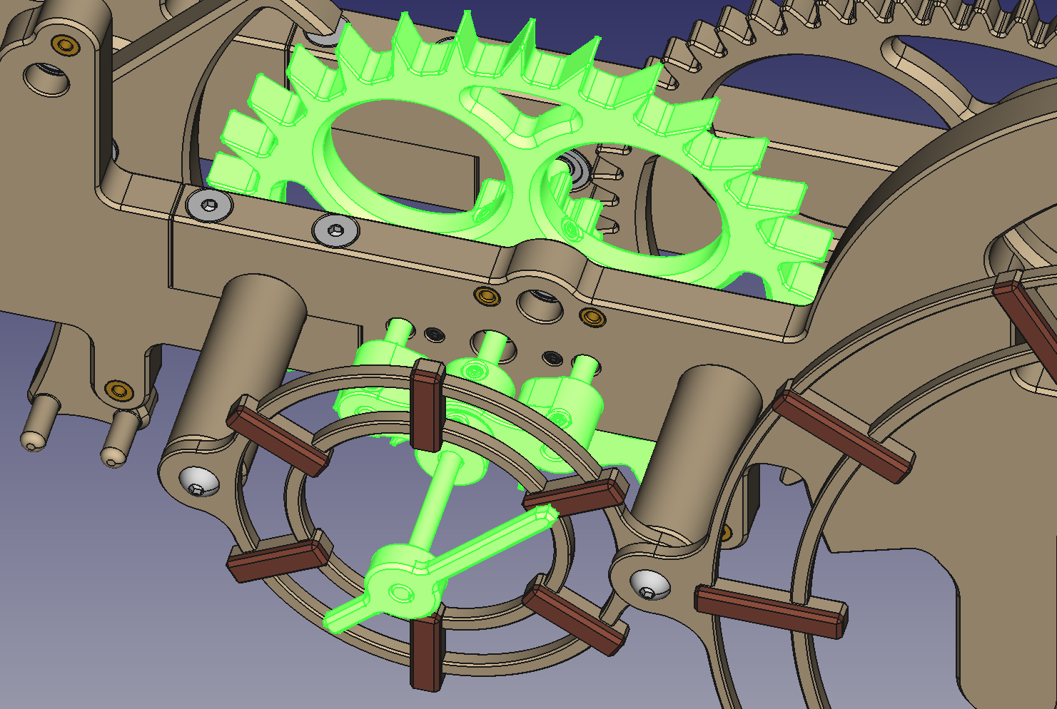
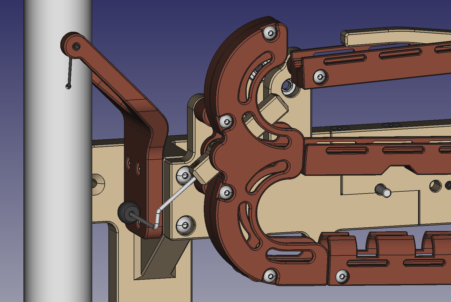
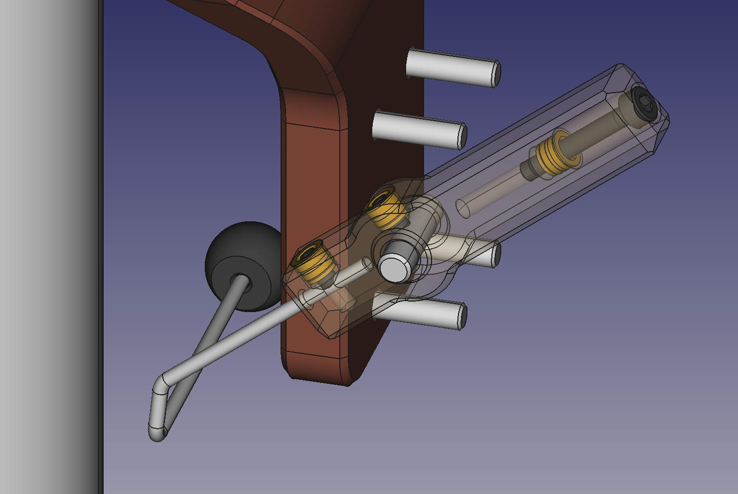
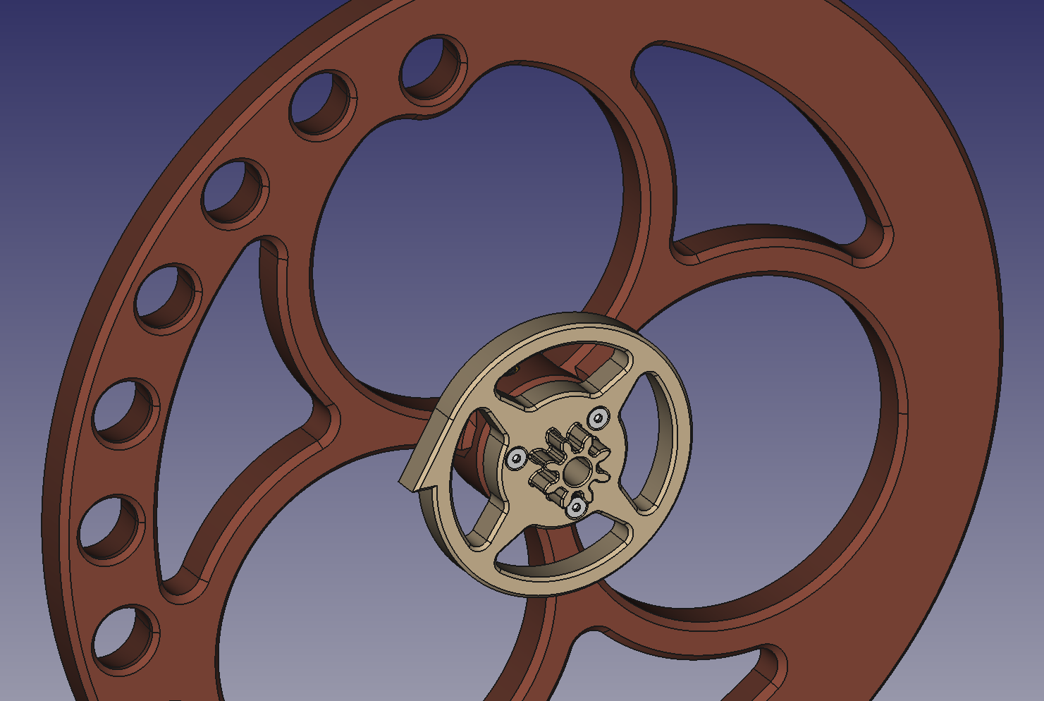
Some of the YouTube videos showed the marble lift wheel being manually rotated (to show how the mechanism worked) without the pendulum, nor the yoke swinging. This indicates that the Graham Escapement they used has a position that allows the escape wheel to freely rotate. I don't like that option so the Graham Escapement design I settled on has a positive engagement (the escape wheel cannot advance without the pendulum swinging back and forth). Unfortunately that would make setting the time on the clock quite tedious. To alleviate this issue I designed a way to disengage the Escape wheel from the gear train. Since the escape wheel rotates once per minute, attaching a second hand to the axle of the escape wheel allows an easy way to mark the seconds and provide a means to push a pull the escape wheel in and out of engagement.
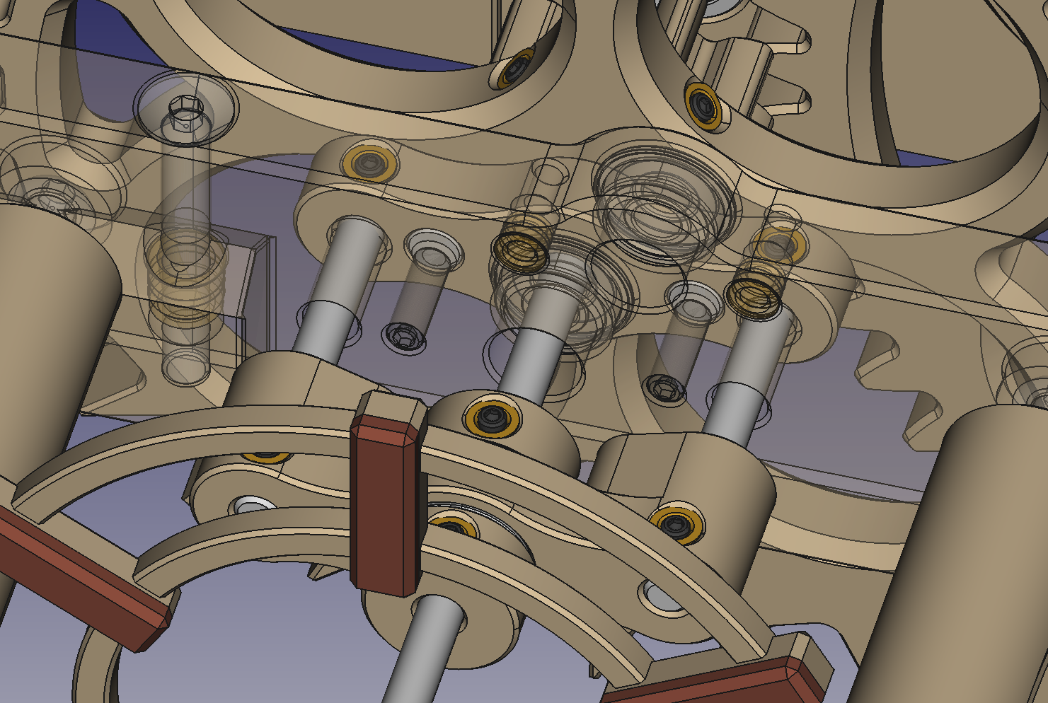
The guide block attached to the seconds axle provides travel limits to the escape wheel's axial movement. To make the escape wheel lock into the ends of travel I provided magnets on either side of the guide block that will stick to the the M4 grub screws that are threaded through the front frame.
Adding the second hand made it a must to add in a clock face, so I went with a simplified version that is mounted on stand offs from the front frame.
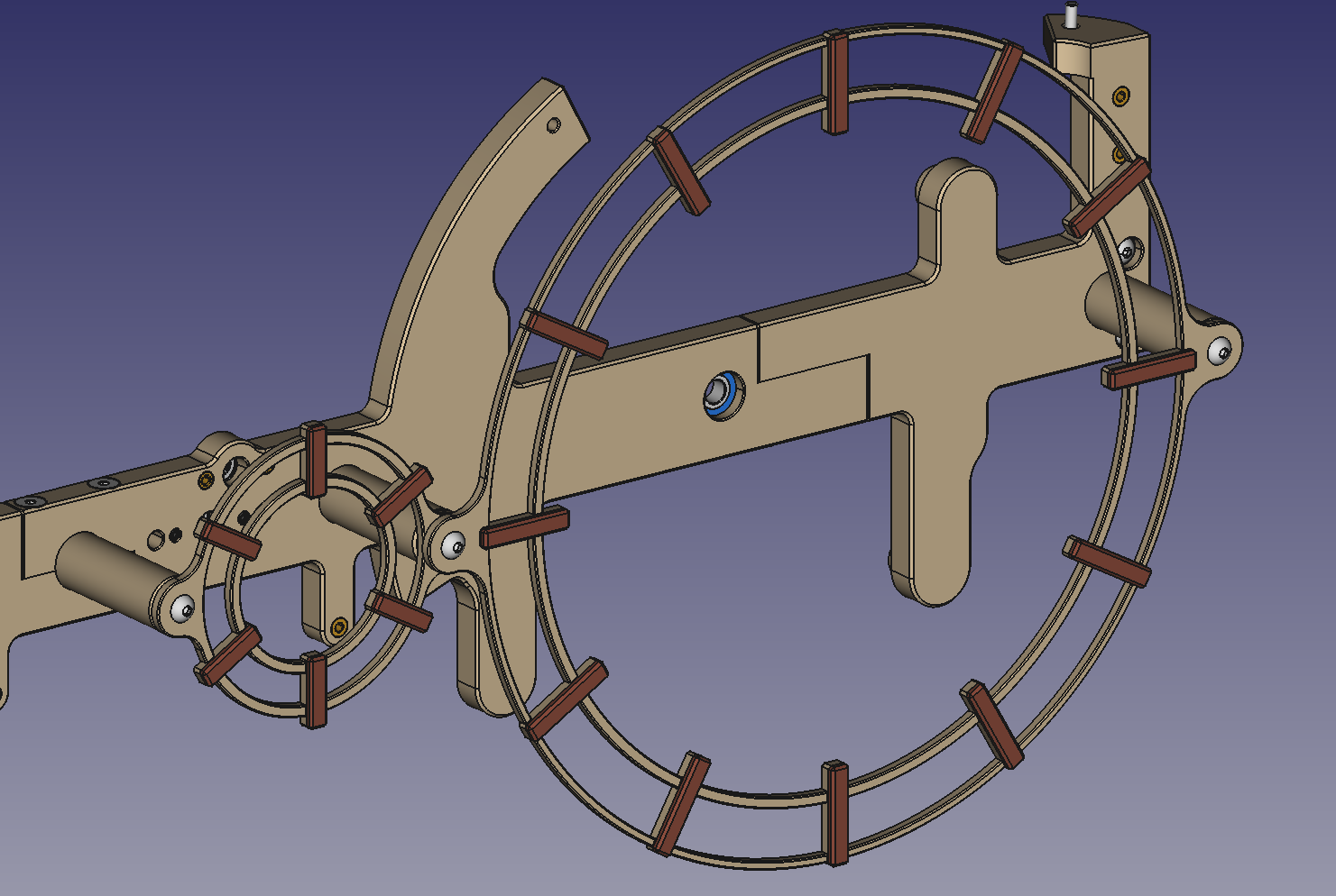
The standoffs for the provide very convenient stops to limit the rotation of the teeter totter accumulator.
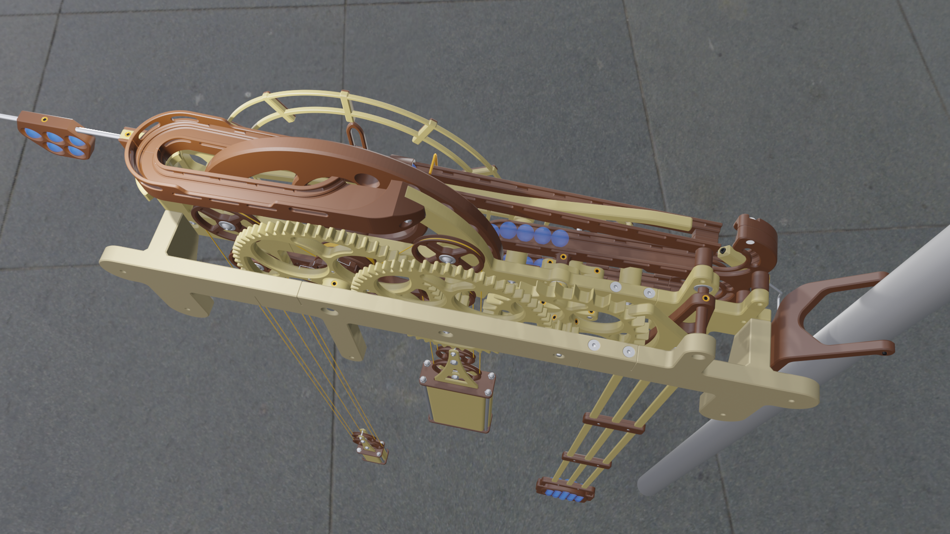
As this is a 3D printed clock I was able to design a one piece bottom storage rail that incorporates marble guides that will prevent the rapidly moving marbles from jumping off the rail when the teeter totter accumulator discharges its load of 12 marble all at once.
The marble return is printed in two halves to eliminate printing supports, and make it easy to inset the gong trip hammer.
The gong striker hammer includes a somewhat hidden balance adjustment screw to allow for the fine tuning of the hammer's balance.
Fine tuning this design may take a few iterations as I am only guessing where the combined C.G. of the striker hammer assembly will be. I plan on printing the hammer's ball out of TPU and the infill of the ball and hammer body can also be tweaked to allow for a better balance.
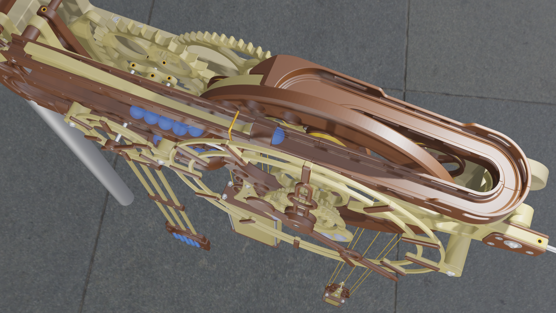
The driving force for the clock is the traditional falling weight. The drive weight is paired with a much lighter winding weight that will travel up as the drive weight falls.
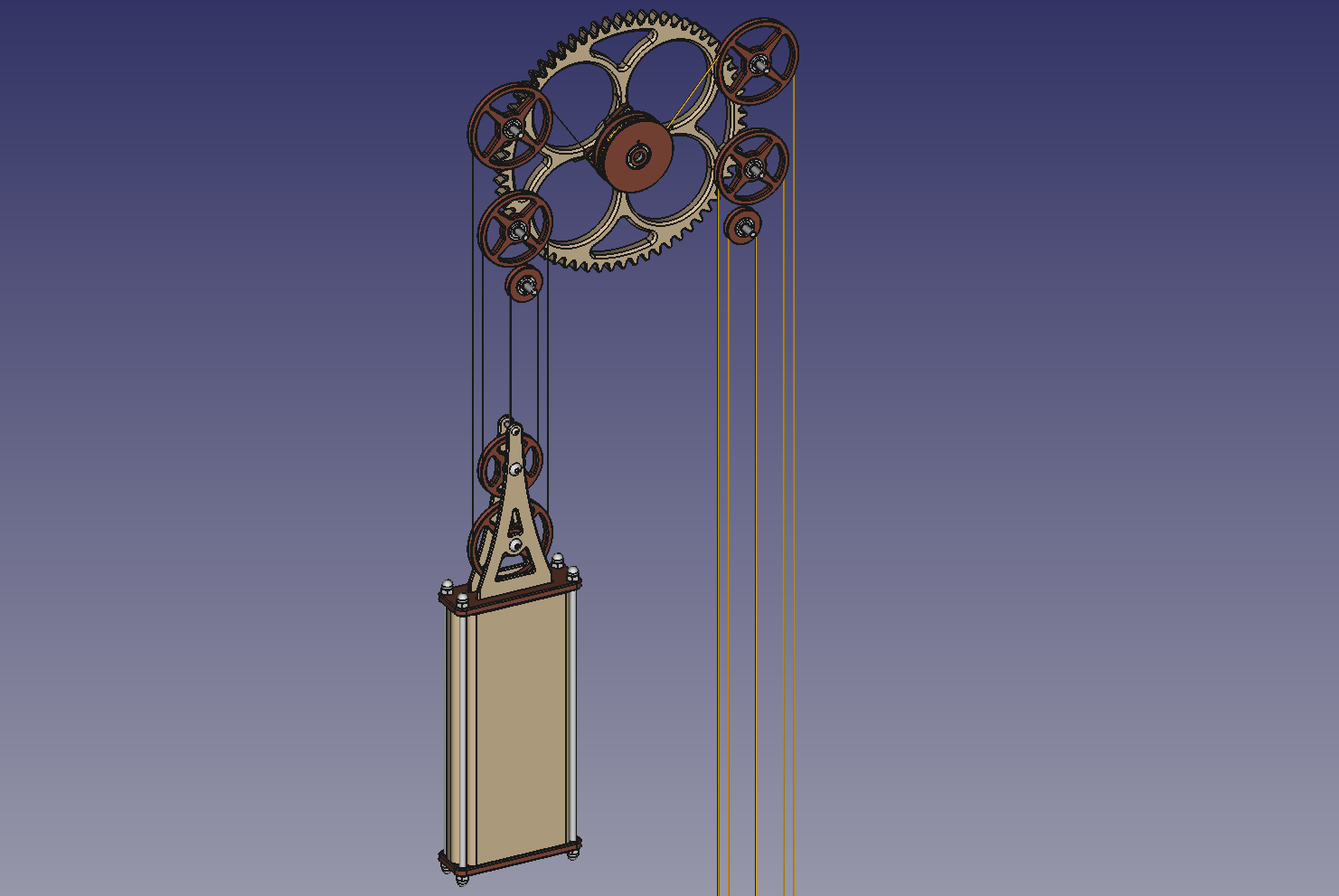
I decided to use a vertically stacked 5 part block and tackle assembly to allow for use of a cord that is five times the fall height. As I plan on using a 1mm diameter braided Kevlar cord for the weights, I think that a 1.8 meter fall will power the clock for 3 days. A smaller diameter cord will allow for more wraps to be stored on the power drum, but will require a longer drop.
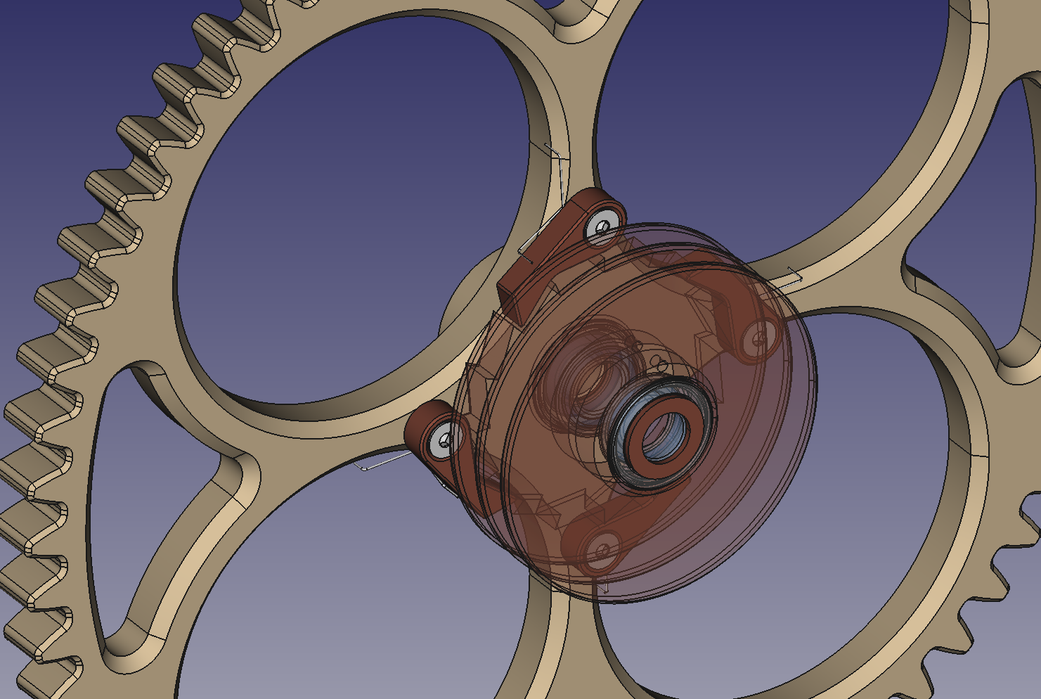
Winding the clock is accomplished by pulling the winding weight down, which will spin the drive drum on the minute axle with a ratchet and pawl mechanism.
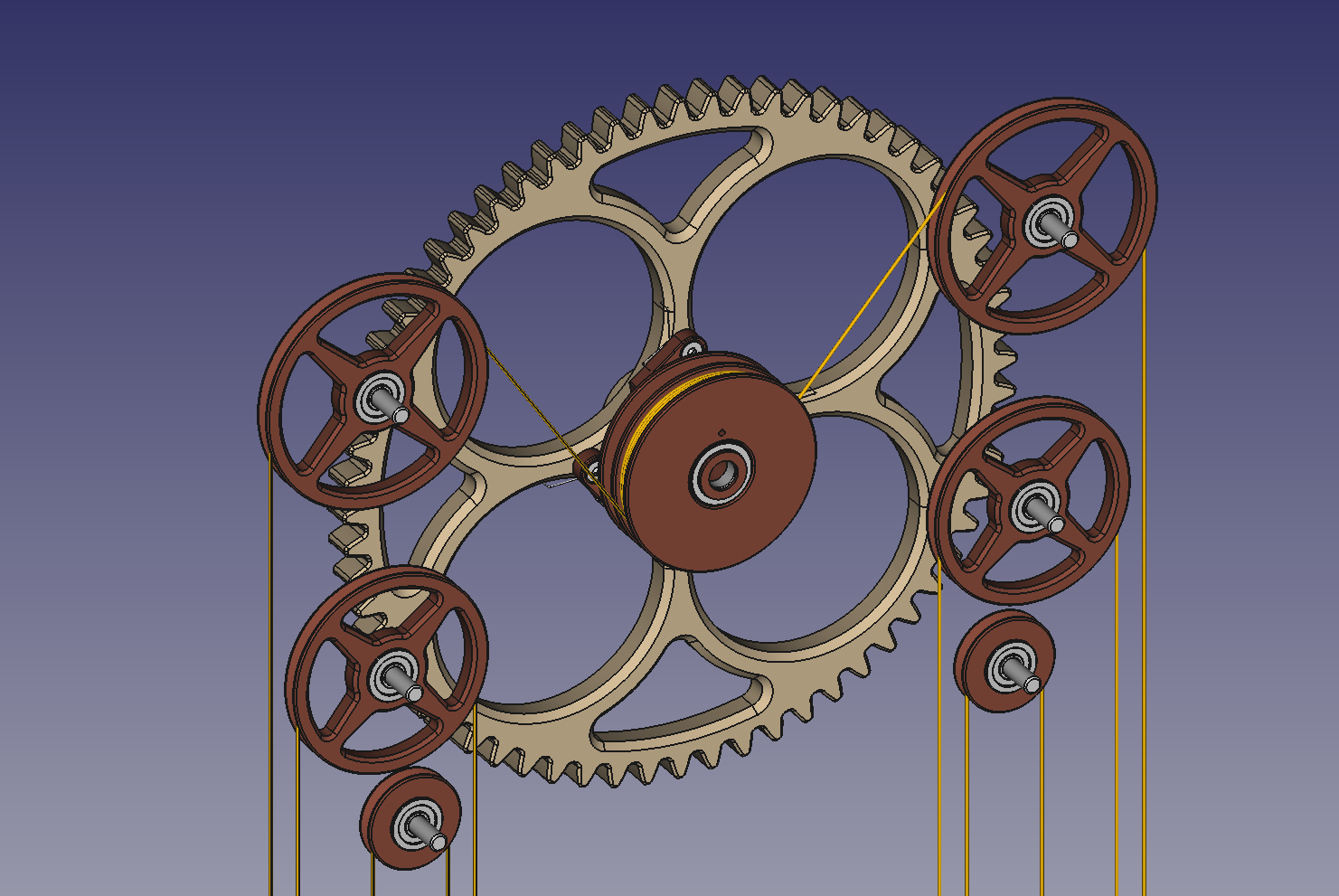
The hour hand is powered from the minute axle via a weighted free swinging gear train. The gear train is driven by an 8 tooth pinion that is built onto the marble trip cam.
The 8 tooth pinion drives a 32 tooth gear which is connected to a 10 tooth pinion through bearings in the weighted frame that pivot on the minute axle.
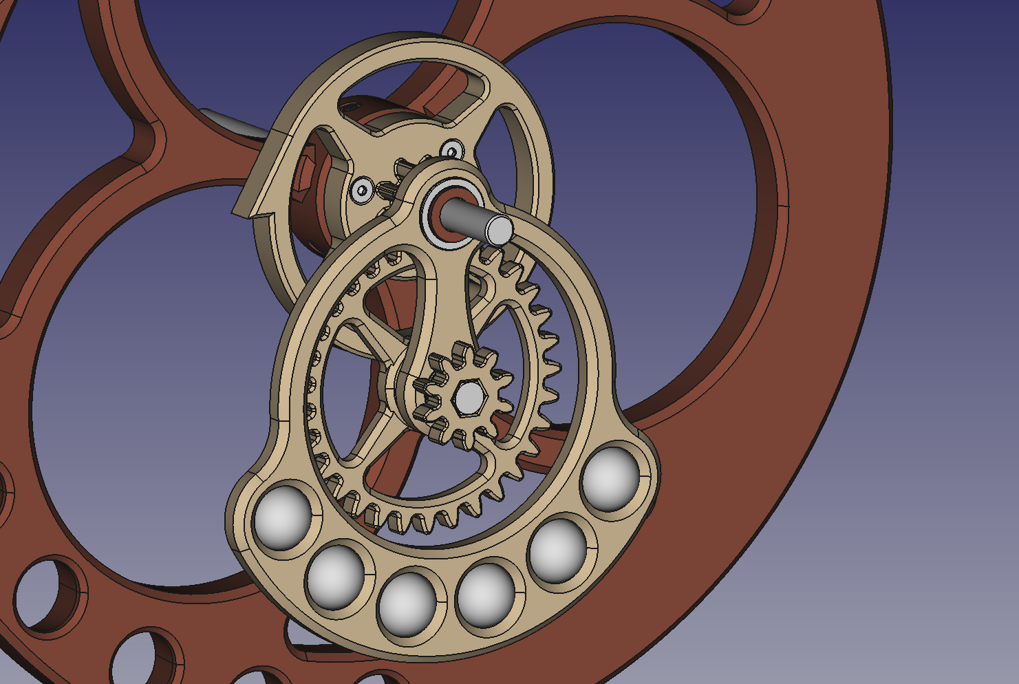
The 10 tooth pinion drives a 30 tooth gear the will rotate once ever 12 hours and thus has the hour hand attached to it.
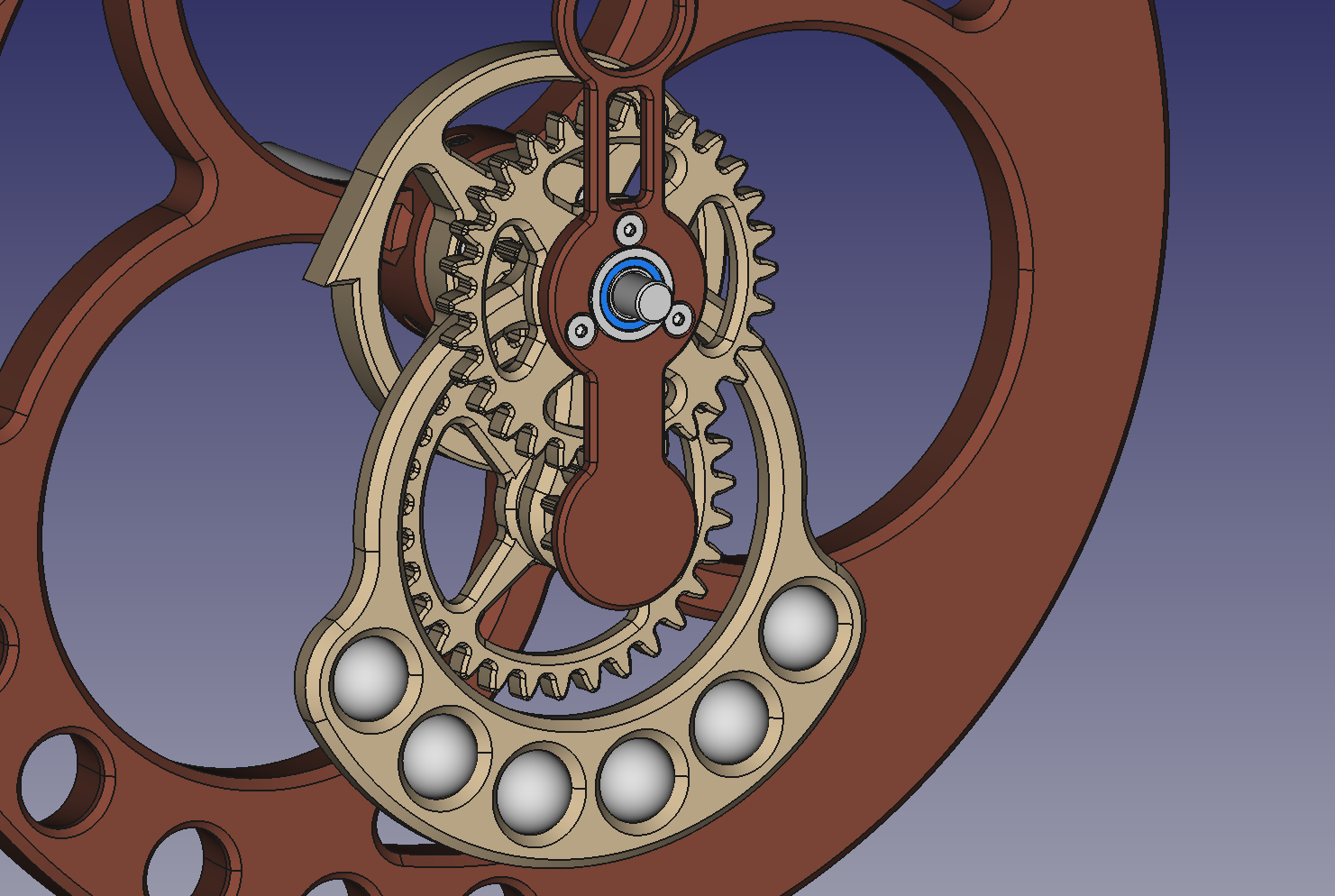
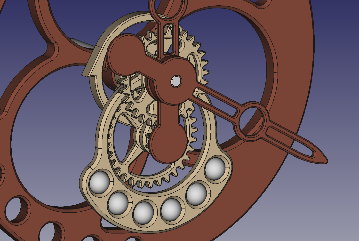
Finally the minute hand is fastened to the minute axle, keeping all the gears in place by the judicious use of shim washers.
While most parts will fit on the printer bed, the longer parts such as the Front and Back Frames, the Feeder Ramp, and the Trip arm will be split into 2 and 3 parts that can be screwed together to make the parts as long as needed. The 1 meter plus pendulum is made from multiple parts as well, but would not call it a split design, as making is like I did added to the over all lateral rigidity.
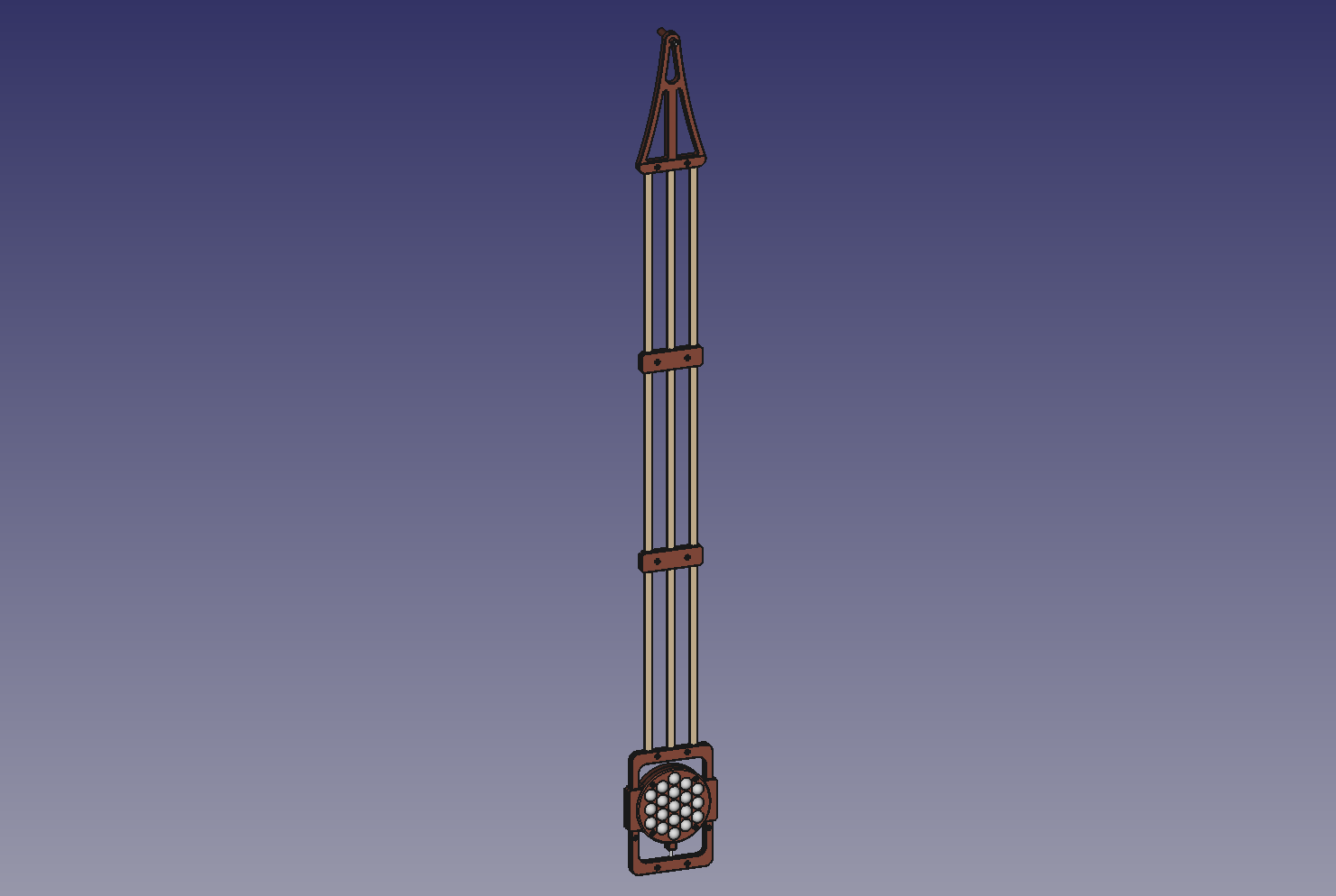
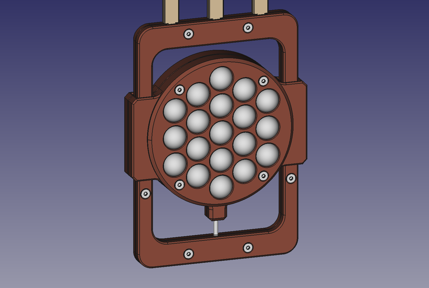
The pendulum bottom frame allows for the weight to be adjusted up and down with a screw so that the combined center of gravity for the pendulum can be adjusted to get a one second period, Currently the weight is made up of two have that are screwed together and hold a combined 38 marbles. I expect that is on the heavy side, and can be easily adjusted by reducing the number of marbles.
Now it's time to get printing, and might end up with a very colorful first article as I use up the ends of spools.
And hear are a few extra renders, just for fun.
.