 agp.cooper
The Audio Interface
Connecting the microprocessor (uP) to an 8 ohm speaker and to an 8 ohm speaker used as a microphone is tricky. Tricky if you want it clean (no PWM in the out put) and simple (i.e. low part count and garden variety components).
Op Amps
The problems here are simple power supply, voltage swing, input noise and output current capacity (i.e. output impedance).
The old single supply contenders (from my local electronics store) are:
- LM324
- LM3900
- CA3140
With a newer:
- LMC6482 or LMC6384.
None of these are low noise but the LMC6482/4 is rail to rail and rated at 600 ohm output impedance. So none of them will drive an 8 ohm speaker directly.
One option is to add a push-pull transistor circuit to the output:
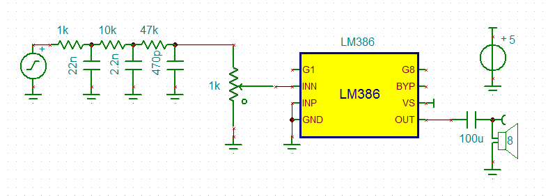
LM386
An LM386 will drive an 8 ohm speaker directly and has a 50k imput impedance, gain is programmable from 20 to 200.
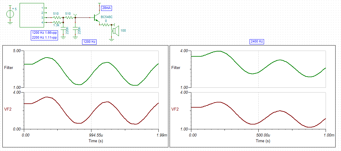
For this application, an LM386 has merit. The gain bandwidth (5Mz) and input impedance is high enough for a multi-feedback band pass. Here is a schematic of a Sallen Key band pass:
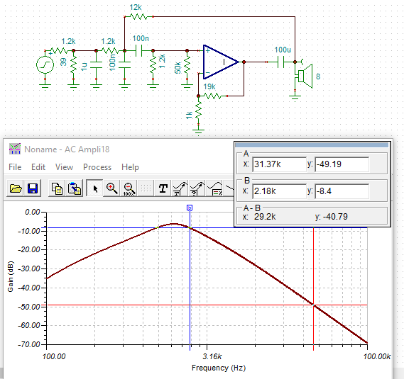
I have used an ideal OpAmp instead of the real thing as TinaTi does not have it.
The gain of the 386 has been set to x20. As the 386 has an output voltage swing of the supply voltage less 2 volts, the 5v PWM input has been attenuated for an output of 2.5 volts peak to peak. I added a 1u capacitor to the attenuator network to roll off the high frequency faster. I have not shown the zobel network or the other 386 circuity.
Transistors
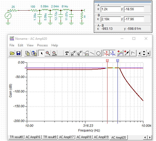
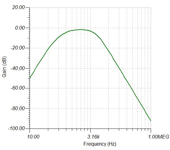
No problems, here is a narrow band speaker driver/buffer:

Note that the 25R is the atmega328p output impedance but the 100R is to limit the current to the maximum permitted.
And here is the frequency response:

The buffer has a -7bB loss but the 31kHz PWM frequency is attenuated a further -28dB.
Quiescent current is about 13 mA according to the simulation.
A speaker microphone input circuit would look like this:
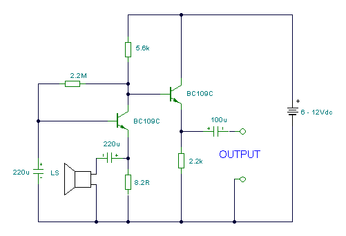 Source: www.next.gr/uploads/51/sp_mic.gif
This image is a common base followed by a common collector (an emitter follower). (The emitter follower is rather useless here!)
Transformers and LC Filters
Good audio transformers are bulky and expensive.
I did spend some time looking at LC impedance matching but high Q (low resistance) components are also quite bulky. I have some suitable toroids (FT-68-??) that are good to 300kHz with an Al of 1.06 uH per turn.
Here is the type of design I have looked at:
Due to impedance matching the circuit delivers x3.4 the power to the speaker than using just a 100R to limit the current. Other than the steep high frequency roll off it does not seem worth it.
A good place to put the LC filter is on the output of the audio amp:
Two Options Done
I have designed a transistor and a LM386 versions.
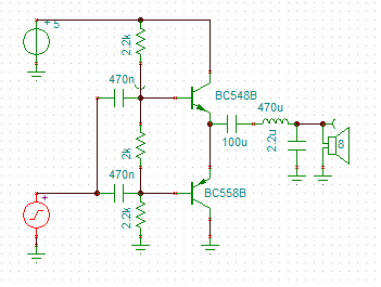
The Transistor Version
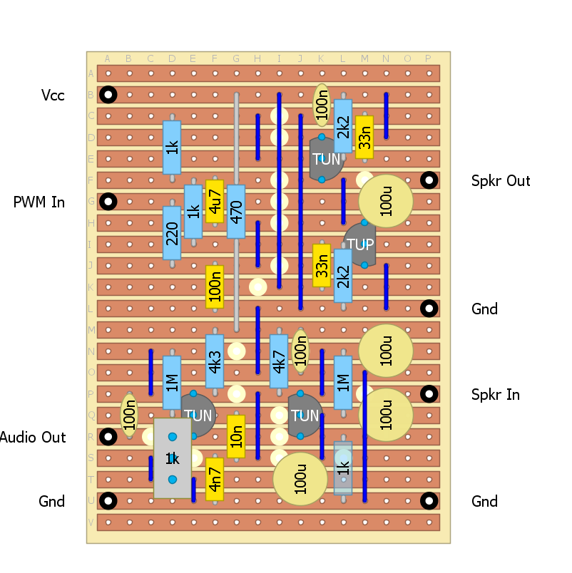
Here is the transistor version strip-board design:
Here is the final PWM buffer:
And the final pre-amp:
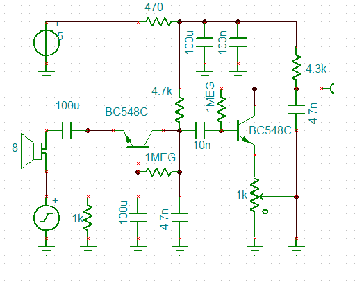
The problem with the transistor version is that at this level of complexity it will need to be debugged (built and tested in stages).
The LM386 Version
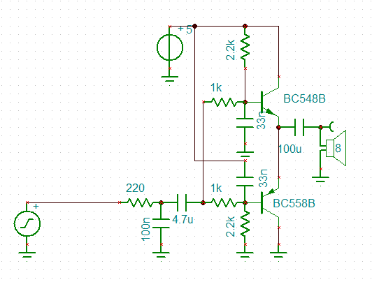
Back to the LM386 version:
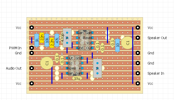
Here is the PWM buffer (less the Zobel network):
The LM386 spice model came from https://hackaday.io/g4lvanix
(https://github.com/g4lvanix/Spice-models/blob/master/sub/LM386.sub), thanks.
Still Not Good Enough!
The LM386 version is at the near foolproof stage, the lesson appears to be that PWM is a "tough nut to crack".
Two thoughts:
- The power output for a an acoustic iPhone modem needs only to be a few mW rather than a max power of 75 mW available from the LM386 (except for experiments using a "loud" speaker).
- A simple resistor ladder for direct digital to analog conversion would simplify the filtering requirements (and free up a timer).
Solving the DAC Maths
To solve this problem I created a simple spreadsheet and modelled a HP RC filter and a LP RC filter.
A LP RC filter can be modelled as exponential smoothing:
- y[i] = a*y[i-1]+(1-a)*x[i]
Where:
- x[i] is the raw input at time step i
- y[i] is the filtered output at time step i
- a is a constant between 0 and 1
If T is the time step T between samples then:
- RC = T*(1-a)/a
- Flp = 1/2/Pi/RC
Similar for a HP RC filter:
y[i] = a*(x[i]-x[i-1]+y[i-1])
And:
- RC = T*a/(1-a)
- Fhp = 1/2/Pi/RC
I solved these by hand many years ago but you can find them on Wikipedia.
The centre frequency we are interested in is the geometric mean of 1200Hz and 2200Hz:
- F0=(1200*2200)^0.5
- =1625 Hz
I used the Excel Solver to minimum error squared by adjusting the HP and LP filter "a" constants. I also adjusted the duty cycle of the digital outputs. Here is the results:

I only used the last cycle was used for the error measurement.
The optimised parameters were:
- LP corner frequency: 659 Hz
- HP corner frequency: 3853 Hz
- and the digital duty (i.e. the time spent at 0 or 2): 126 degrees
The digital duty is not an important parameter and 120 degrees would be fine.
Designing the DAC Ladder
To start I modelled a simple 2R-R ladder, here are the results:

Need some work to increase the output voltage and reduce the output impedance.
Here is the improved version:

All that is need is a buffer to drive the speaker.
Decimating the Design
After designing the R2R ladder I thought it would be a good idea to "Decimate" the design (i.e. ruthlessly reduce the part count). So I was looking at a summing DAC like this:
 This can be reduced (if voltage can be sacrificed) to:

At this point I realised the bottom 1k resistor could be replaced with a capacitor:
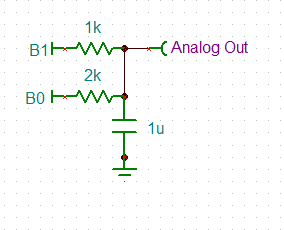
Now that is "two birds with one stone". But what is the RC constant for this? No wantibg to do the maths:
- If we assume B1 and B2 are in phase square waves then the RC constant by inspection is R1*R2/(R1+R2)*C and the voltage gain is 1 (for low frequencies).
- If we assume B1 and B2 are out of phase square waves then the RC constant by inspection is R1*R2/(R1+R2)*C and the voltage gain is 1/2 (for low frequencies).
So neat, no complicated maths.
So here is my second order low pass design:
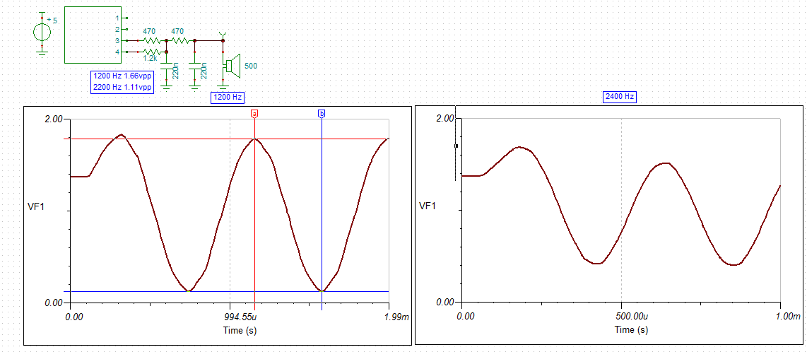
Note in selecting the RC constant I have a choice:
- select an RC constant that has similar output voltages for the mark/space frequencies as per the previous designs and accept the high frequency noise, or
- select an RC constant with minimal high frequency noise and accept different output voltages for the mark/space frequencies (the mark frequency being attenuated).
For the FSK demodulator reducing harmonics is more important than amplitude variations. Thus the RC constants used in the above schematic.
In the above schematic I have shown a 500 R speaker? Well I forgot that I originally intended to use these 35 mm diameter ceramic speaker that I have, rather than the 8 R speakers I have been battling with.
Although ceramic speakers are more efficient then the equivalent sized moving coil speaker, I suspect 1.1 to 1.7 vpp (0.3 mW to 0.7 mW) will not be loud but quite adequate for an acoustic modem.
More Ruthlessness
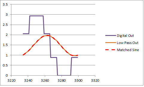
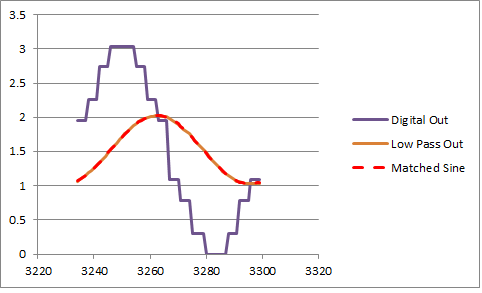
If I drop the second low pass, I get higher speaker voltages and not unreasonable signal:
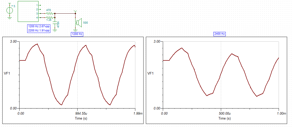
The above power outputs are 0.9 mW for 2.2 kHz and 1.8 mW for 1.2 kHz.
It is worth looking at how good the 2 bit summing low pass filter is:
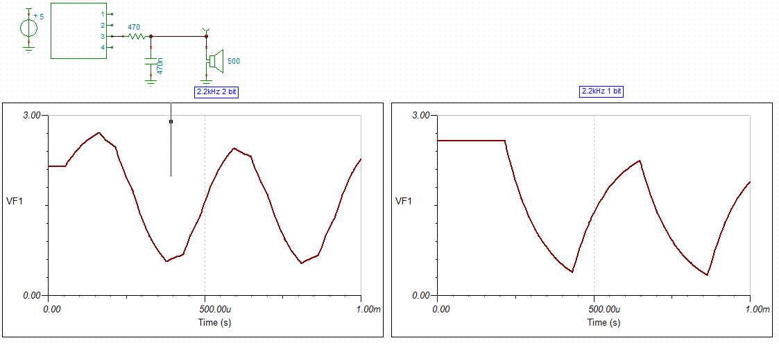
The difference between 2 bit and 1 bit in the above image is pretty impressive!
I think the first order 2 bit DAC with the ceramic speaker should be sufficient for the application.
The datasheet for the ceramic speaker suggests that the they should not be subjected to a long term DC voltage, so a 1 uF decouple capacitor is required (not shown).
Well that was Disappointing
Here is the assembled modem:
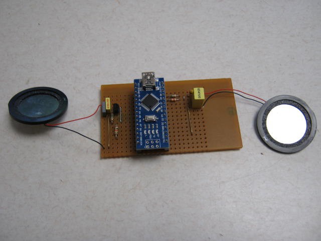
First problem was that the sound level was very low. Think of a whisper (~20dB)!
Checking the wave form on the speaker, is was as expected:
- 2.5 vpp at 1200 Hz
- 1.8 vpp at 2200 Hz
That is a very bad speaker. These speakers don't match the muRata spefications (for VSB35EWH0701B). They should deliver 70 dB for 1v rms (~2.8 vpp) at 10cm. 70 dB is a vacuum cleaner at 1m!
On the input side the audio output after 40dB amplification was only a few mv. These are very bad microphones.
Basically they are going in the bin and I will buy something else. I may as well buy some proper microphones as well.
Audio Output Test
The output signal is as expected unless you send random data. Then it breaks up. it can not handle the frequency shift. So I will have to use the second low pass filter option.
Updated Second Order Low Pass Filter and Buffer
After checking what was available, I settled on a 30 mm diameter PCB mount 100 ohm speaker. The AST-030C0MR-R is rated at 80 dB at 10 cm with a 0.1 W (9 vpp) input.
Here is the schematic:
The zero ohm resistor in series with the speaker allows the volume to to reduced as required. The emitter follower has just enough free-board for 3 vpp input.
As an experiment I used a 40 mm 8 ohm speaker with a 97 ohm resistor in series, to test the output loudness. The volume is probably about 20 dB as the power to the speaker is only about 250 uW. A little louder than the ceramic speaker but not much. With a 30 mm diameter 100 ohm speaker, the output power will be about 4 mW. This has an apparent loudness of about four times.
Watts to dB
My estimates of dB loudness are basically guesses so time to injects some science.
I found a reference that suggests a typical HiFi speaker delivers about 85 to 92 dB at 1 m. The AST-030C0MR-R is rated at 80 dB at 10 cm for 0.1 W power input, that is the same as 80 dB at 1 m for 1 W power input. A speaking voice (at 1 m) is about 60 dB. So the required input power is 100 mW from these 30 mm speakers for a speaking voice. As the input power is expected to be 4 mW (-48 dB) then the output loudness will be 32 dB. 250 uW is -72 dB so the loudness is 8 dB (n.b. 10 dB is breathing!), so my above guesses of 20 dB were way off!
For this application, the modem is relying on being less than 1 cm away from the iPhone microphone and as the iPhone is happy to be talked to from a metre away, we can add 40 dB to the 32 dB to get 72 dB so the iPhone should be able to handle it.
Modelling the Summing Capacitor
I ran a simple simulation of the summing capacitor model in Excel and got very similar optimisation results to my "eye-ball" of the Tina-TI simulations:
- Bit 1: 510 R (fixed)
- Bit 0: 1k2 instead of 1k3
The output voltages from Tina-TI are now :
- 2.38 vpp for 1200 Hz
- 1.38 vpp for 2400 Hz
The optimisations were designed to minimise the harmonics (i.e. best sine wave for 1200 Hz) and was based on a summing DAC and a low pass filter of 1 vpp output:
I reworked the code for a 3 bit DAC:
- Bit 2: 510 R
- Bit 1: 1k2
- Bit 0: 3k3
AlanX
Discussions
Become a Hackaday.io Member
Create an account to leave a comment. Already have an account? Log In.
I played with those $0.30 3W class D stereo amplifier (Diode Inc PAM8403) modules from China. They run on 5V. I used them for a different project and they sound pretty good.
I blew it up the last one on the prototype. Unfortunately there is still a backlog at Canada Custom for stuff from China that delayed to beyond 60 days for half a dozen of my orders. That kind of killed the contest entry.
Are you sure? yes | no
Hi Lee,
You project would have got my vote but most people would not appreciate the work and what it actually does!.
I spent half a day looking at a Class D. Not hard but I did not feel like a winding yet another toroid. I ordered a couple online but they will take a few weeks.
The Class AB is going okay. About an 1" square on strip-board:
I am currently designing the pre-amp. Too much gain at the moment.
---
I guess the customs problem is politics. I read an article a few days ago called "Mad As Hell - Why the public is so pissed off" by Chris Martenson, in the US which seems to sum things up:
"Cell phone plans in the US are 2x to 3x more expensive (and more limited in terms of both data and speed) than any of the other countries I've traveled to in the past few years. A phone bill from AT&T in Hong Kong is a single page long and clearly explains how your unlimited high speed plan ended up costing you around $30/mo. In contrast, my bill from the same company in the US runs about 30 pages, and seems intentionally opaque in helping me understand why I'm spending over $100/mo for a limited data plan with much slower speeds."
Just to check: the Australia Post overseas mail cost was two clicks and one page, the US post was two clicks (with far too many options) and 72 pages. So I guess it is true!
AlanX
Are you sure? yes | no
Canada custom is only going to get slower as there are deadly illegal drug coming in from China. Some were hidden in printer toners. It used to take 3 weeks, then went up to 4 then 6 and now 8+ weeks. :(
Also the Custom are not answerable to anyone here. We also stuck with the lowest import exemption - just $20. They lost money collecting even after they charge $10 for processing.
Canada is actually worst than US in terms of lack of competition. Food prices has been well above the inflation rate for the last few years. It is not like we don't grow food here.
Are you sure? yes | no
Hi Lee,
Now a Dalek voice changer did cross my mind before. Nice to see someone having a go.
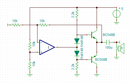
The rail to rail Op Amp would help. In your design, as the supply voltage is regulated, then the diodes can be replaced with resistors. I took advantage of that to increase the high frequency roll off with a low pass filter. Checking the cross-over distortion, I found 1k with a 2k2 bias resistor worked well (in the simulator). The quiescent current I think was 13 mA. It is hard to find another design that is better.
To get more volume in your case just drop the speaker resistance from 8R to 4R (two parallel speakers?). Your design should handle 4R easily.
The only other thought is go Class D rather than class AB. Perhaps a DRV8825 into two LC LP filters as shown below (~1.5W from 5 volt supply):
Actually I think I will have another look at Class D. The toroid I have is only 0.7" across so in the end it take no more real-estate than the other designs.
It is a really tough problem avoiding the humble audio transformer!
Regards AlanX
Are you sure? yes | no
The diodes are there for temperature compensation for the output transistors. Without them, the bias point would drift as they get warm.
Are you sure? yes | no
Hi Lee,
If you need something in a hurry, just use an LM386 with a 26dB to 30dB attenuator at the input. The peak to peak voltage drop is about 1.5 to 2 volts depending on how much THD you can handle. That is about 200 mW with a 5v power supply.
AlanX
Are you sure? yes | no
You always see the diodes in these circuits, but not always the advice that they should be thermally coupled to the output transistors. If the transistors get hot, but the diodes don't, they won't provide much compensation. Ideally, the diodes would always be at the same temperature as the transistors.
Are you sure? yes | no
I haven't used one of those since first year University, so I don't have them in my collection of parts. I had a LM386N from a modem that i have put aside for the project and because of that I couldn't find it.
I have seen transistors (wired as diodes) or thermistor mounted to heatsink or same metal clip on the output stage.
Details like that seems to drop out when people copy/paste design without understanding and gloss over it over youtube. It is just another form of foodies photographing what they consume on twitter without the skills of cooking.
Are you sure? yes | no
BTW This is what I have tried on Class AB amplifier. I didn't play with a rail to rail output opamp, so you might have a bit better luck getting higher volume than 50mW out of it. The THD is about 1%.
https://hackaday.io/project/18904-dalek-voice-changer-in-1kb/log/50395-class-ab-amplifier
Funny how similar the circuit is. :)
My original idea was actually tried to make a class D by using a NPN/PNP buffer stage driven from the PWM digital output, but it was noisy.
I also tried a RC bandpass filter, but blew up a class D amplifier chip in the process.
Are you sure? yes | no