 Tamas Feher
In the next log, I will choose the motor for the actuator. To be able to do so, I will need to set some requirements. Mostly:
- Maximum stroke length
- Maximum output force
- Maximum velocity
My way of figuring this out spawns from quadcopters (Bear with me on this).
A general (often wrong) rule of thumb when sizing the motors for a quad is to have twice the amount of thrust that's needed to hover. Why is that?
It boils down to control authority. Which means how much can you influence your controlled variable.
For your system to be effective, there needs to be enough control authority to perform the intended action, and some more to be able to compensate for disturbances. Going back to the quadcopter example: If the motors are producing a 100% thrust just to hover, they don't have enough headroom to control the tilt of the craft. Any small breeze would send it spinning, making it unstable.
That's why the output thrust is chosen to be what's needed, and some more on top of that.
Doubling the value is an easy guesstimate that can be tuned further once the prototype is ready.
In this case, we can start the analysis by looking at the most demanding use case, which is the fast circling of the ball.
The speed of circling is 200 Deg/s, and the diameter of the scribed circle is 130mm.
The linear velocity (blue arrow) of the ball can be seen changing direction, but not magnitude.
The change in velocity direction is due to centripetal acceleration (red arrow). To calculate the magnitude of this acceleration we can use this formula:
where:
- a is the centripetal acceleration
- omega is the angular velocity
- r is the radius of rotation.
Plugging the values into the equation we get a = 0.792 [m/s^2]
The ability to exert acceleration on the ball is our control authority. So this is the value we will double to give enough headroom. Giving us a = 1.584 [m/s^2]
The next topic is about how can we influence the acceleration of the ball through tilting of the plate. I will not go into the breakdown of the dynamics of a sphere rolling on a slope, but here is the formula:
- g is the gravitational acceleration g = 9.8067 m/s^2
- phi is the tilt angle of the plate
Rearranging the formula we can get the maximum plate angle needed, which is 13.069 degrees.
So now we've got a requirement: The plate needs to be able to tilt +- 13.069 degrees.
Next we can analyse how fast we need to be able to tilt the plate. The plate can tilt in pitch and roll directions.
If we look at the plate from the side, we can see that during motion it tilts in a sinusoidal wave.

We can express the plate motion through this formula:
Through derivation, we can express the plate tilt angular velocity:
The upper limit of this function is where cos equals 1, meaning our maximum plate speed is the maximum plate tilt times ball angular velocity, which is 0.796 rad/s
To get the maximum plate angular acceleration, we can derivate once again:
Once again expressing the maximum value of this function by replacing sin with 1:
Plugging in the values for the equation above, we get the maximum plate angular acceleration: 2.779 rad/s^2
Now we are finished with analyzing the plate, and we can move on to analyzing the linear actuator capabilities.
Now moving on to evaluating the needed stroke length for the linear motor. for this, we need to do geometric evaluation.
We can consider the center of the plate being pinned in space, and tilting around it.
The first variable we need to figure out is where the piston attaches to the plate. you can imagine a lever here
If it attaches close to the center, the stroke length will be shorter, but larger forces need to be applied and if it's closer to the edge, the stroke length is higher, with lower forces involved.
For visual appeal, I chose a radius of 30 mm, but that can be tuned for the motor selected.
Another important factor is the minimum internal tilt for the actuator is set to be around 20 degrees.
I didn't have the energy to break it down into equations, so I used a neat trick to obtain the values: Using CAD sketches in onshape I can easily get the necessary lenghts for my actuator:
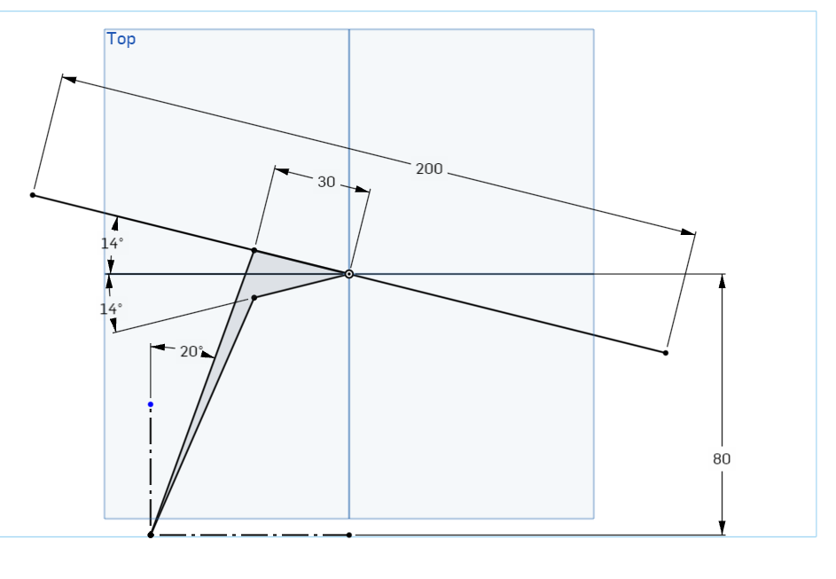
With this I got the minimum actuator length: 79.37mm and the maximum is: 92.85mm. Giving me a stroke length of 13.5 mm
Okay, we are almost there. now we just need to consider the maximum linear velocity, and the maximum force needed.
I'll simplify the following calculations by not considering the internal tilt of the actuator, but rather considering it directly under the 30 mm joining point, making it perpendicular to the plate.
From the maximum plate angular velocity, we can calculate the maximum velocity of the actuator:
To finish up the calculations, we only need to get the worst-case force exerted by the piston. To set up the worst-case scenario, imagine the is plate accelerating the ball upwards with the maximum plate acceleration. The ball is positioned at the far end of the piston assembly.
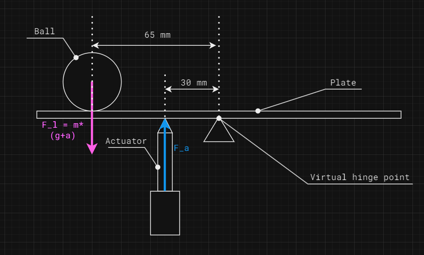
The mass of a 20 mm diameter stainless steel ball is 33g. I'll consider the mass of the plate together with the mass of the ball for simplification.
In the earlier log we've established the technology for ball detection will be contained within a pcb, so we can estimate the weight of the plate by the weight of a 200mm x 200mm pcb, which is approximately 148g.
All together the mass that needs to be considered is 181g
The upwards acceleration of the ball can be calculated through the maximum angular acceleration of the plate
The upward acceleration of the ball comes out to be 0.18m/s^2. It's negligible next to the effects of gravitational acceleration, but I will still consider it, as I put so much effort into calculating it.
From this point we can calculate the force exerted by the ball and plate on the actuator. Taking the lever forces into account:
Expressed from this equation we get the necessary actuator force to be: 3.91N
At this point we can start reintroducing the internal tilt of the actuator, as coming form the onshape analysis, the worst case actuator tilt compared to the plate is around. 37 degrees.
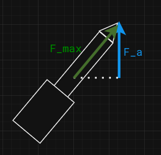
Where Beta is the worst-case relative tilt of the actuator compared to the plate
All together the maximum actuator force comes out to be 4.9N
Through a long and treacherous journey, we managed to obtain all the requirements needed to select an actuator
- Minimum stroke length: 13.5 mm
- Maximum output force: 4.9N
- Maximum velocity: 23.8 mm/s
Is it over-engineering the problem? Certainly. The reason why I went into such depth about the requirements is that I was interested mostly in direct drive applications, where there are no reduction gears. This usually means lower forces. So I wanted to make sure I know what kind of forces I need to deal with before selecting the actuator.
Discussions
Become a Hackaday.io Member
Create an account to leave a comment. Already have an account? Log In.