 Tamas Feher
Now there are enough requirements available to decide on the technology used for the linear actuators. Let's recap what are the relevant requirements:
- The BJR shall be silent during the operation
- The stroke length of the actuator shall be at the minimum of 13.5 mm ( 0.5315 inches)
- The output force of the actuator shall be at the minimum of 4.9N (1.101 pounds)
- The piston speed shall be at at the minimum 23.8 mm/s (0.937 in/s)
Overall this project needs actuators that are fairly quick with low force output. This gives an ideal candidate to direct drive motors.
Direct drive means no gear reduction involved in the drive train. It's beneficial in the sense as well that gear inefficiencies usually add noise to the system, while this project is aimed to be silent.
it's not enough to analyze the force and speed separately, as the actuator needs to be able to produce the prescribed force at the given speed.
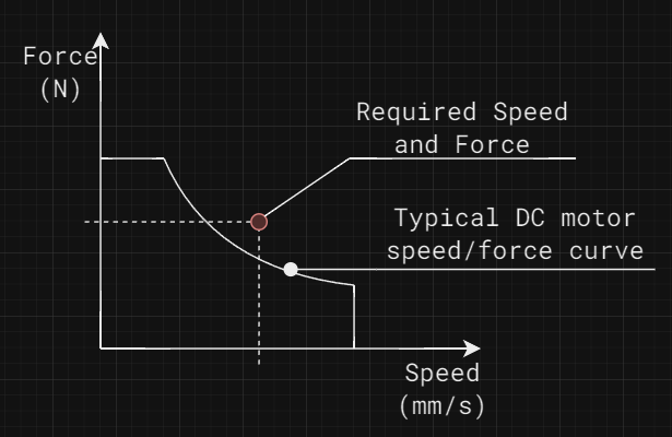
The figure above shows that even though a motor is capable of delivering the needed speed and force, it might not be suitable for the application.
Let's see what technologies we would run up against each other in this trade study:
Linear motors
Linear motor technology has recently evolved a new form of motors, where the magnets are contained within a shaft, and the motor only contains the windings.
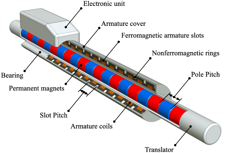
This technology enables very high-speed linear motion. The downside has been the technology did not break into the market yet, and the prices are still quite high. I was quoted over £400 (~498 USD) for a single unit.
Captive linear stepper motors
That's quite a mouthful, so let's break down how these elements describe the technology.
A stepper motor is a type of motor that moves in precise, fixed steps in response to electrical signals. Linear means that the rotation is converted to linear motion, in this case with an ACME profile threaded rod.
In order to make the threaded rod move linearly, its rotation needs to be prevented with something. In this case, it's a sliding mechanism.
Captive in this case means that all the thread, the motor, the sliding mechanism is self contained within the motor assembly, outputting pure linear motion.
An example video can be seen below:
Stepper motors are famous for their silent operation. If you've ever seen a 3d printer in its works you'll see that it makes all kinds of noises. The reason for this is the stepper motors. More specifically the control of the motors. They are not inherently noisy, just they are controlled with a choppy drive signal that causes a lot of harmonics.
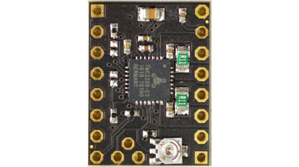
One product that helps us combat that is Trinamic SilentStepStick.
Trinamic's StealthChop offers nearly noise-free running of stepper motors.
Linear DC motors:
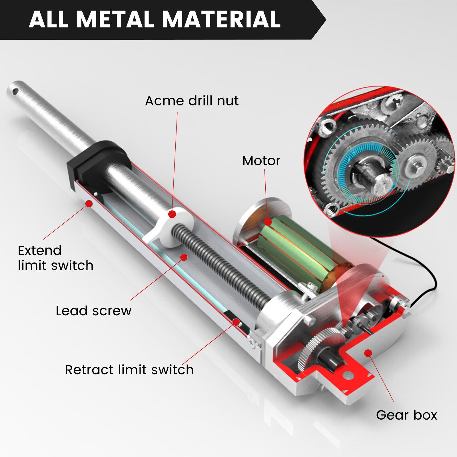
The linear DC motors work under the same principle as the captive stepper motors. This means they spin an acme threaded rod that's prevented from rotating to achieve linear motion. Often these motors contain a gear reduction, which usually injects some noise into the system. However, they are very cost efficient and easy to work with.
Similarly to BJR_LOG_03, I'll be using a decision matrix to decide which technology to use.
Using the same Measures of performance as before:
- Cost
- Time to prototype
- Visual (or audible) appeal
The evaluation looks like the following:
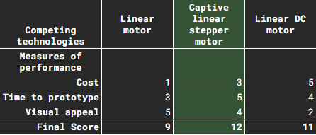
So moving forward I'll continue the design using Captive linear stepper motors for the actuator.
A quick word on position sensing of these devices.
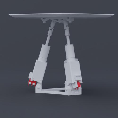
Steppers can be run open loop without a feedback encoder. The only issue is at startup they have no recollection of where the output actually is. To combat that a homing procedure needs to be executed, where the motor goes towards an end position, and an external switch registers when the output has arrived. For this, I'll be using a micro switch mounted at the bottom of the motor. I'll be experimenting with the stepper controller's StallGuard feature, which can detect stalls in the motor. It could be used as an end-stop detection device, but for the sake of safety, I'll still add the micro switches. On the image below the limit switches are highlighted in red.
Discussions
Become a Hackaday.io Member
Create an account to leave a comment. Already have an account? Log In.