 Tamas Feher
Introduction
In the last log, we tried using Capacitive sensing to sense the ball, but that ultimately failed.
In this log, we are going to explore an inductive sensing method to detect the ball's position on the plate.
Inductive proximity sensing
There are multiple ways to exploit inductance for proximity sensing. In this article, we will focus on the resonant sensing principle.
The sensing inductive coil and a capacitor are connected in parallel to form an LC tank circuit. The inherent resonant frequency of this circuit can be calculated as
As a conductive target approaches the inductive coil, eddy currents form on the surface of the conductive target. The magnetic field of these eddy currents resists the current of the inductive coil, which reduces the inductance of the system and increases the resonant sensing frequency.
Here is an example LC circuit with 2H of inductance
And the same example but with half the inductance
You can see that the frequency of resonance has changed and this is the property that we will measure in this experiment. You can find out more about the principle of operation in this
For testing, I'm using the TI LDC1614 high-resolution inductance to digital converter.
Detecting 2d position with inductive sensing
The way I chose to construct the sensing elements is by lining up multiple sensing coils next to each other. The sensing elements are spiral tracks printed on a PCB. They've been elongated into a "Horse race track" shape, so that they would be sensitive to the ball's movement only in one axis. Later tests confirmed that moving the ball alongside the racetrack doesn't influence the measurement to a significant degree.
Multiple of these tracks have been put next to each other and interlaced in different directions on a 4 layer pcb, so that we have sensing resolution in both the X and Y directions.
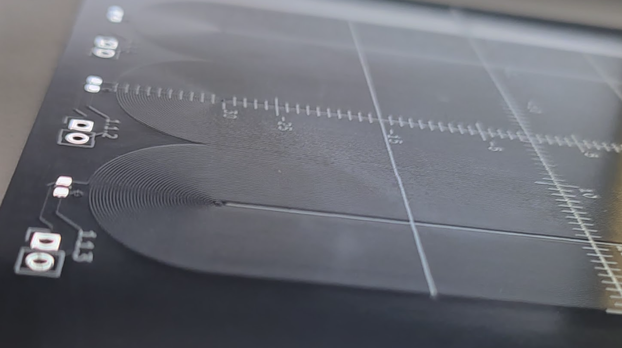
The final test pattern looks like a weaving pattern:
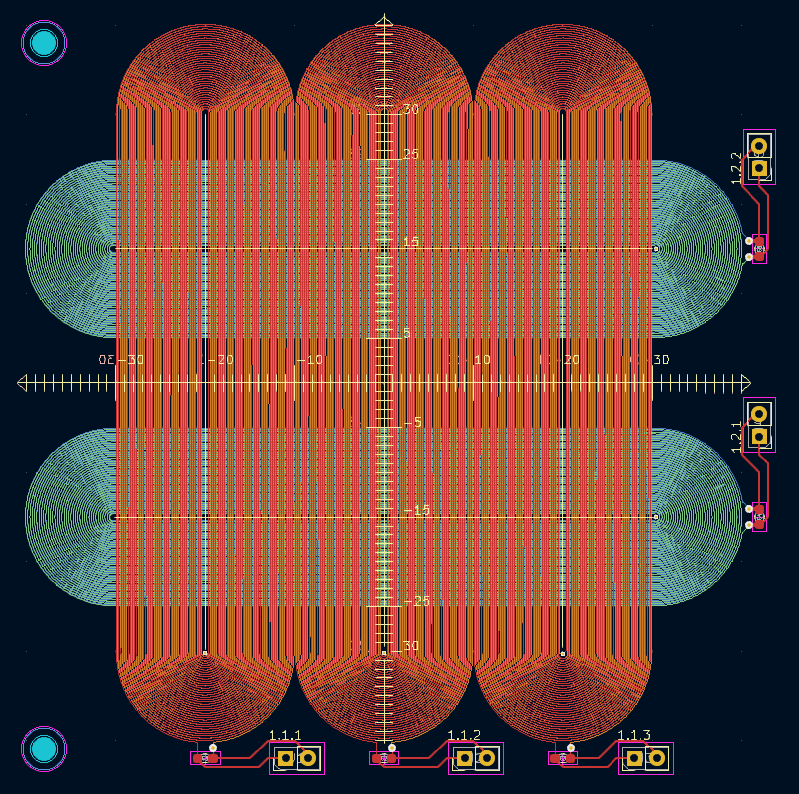
This way the vertical racetracks detect the X position by observing which coil has changed it's inductance the most. Hopefully to sub mm accuracy. Same applies to the horizontal racetracks.
Designing the PCB
The issue with these racetracks is that there is no built in feature in KiCad (Open source electronics design software) to lay spirals out. Doing it by hand would be a grudgingly long job. Instead I opted of automating the process through python scripting.
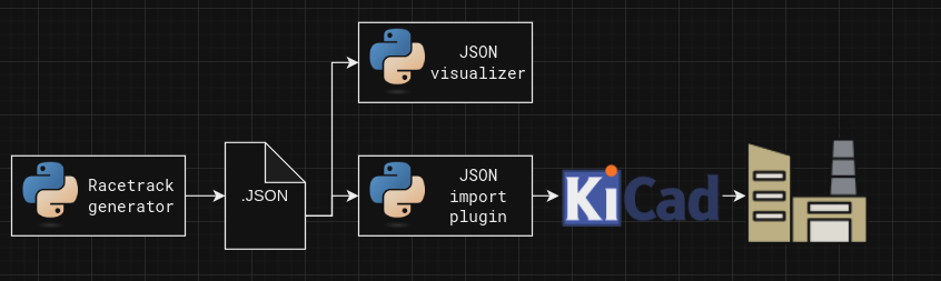
KiCad's python scripting API is a bit difficult to use due to lack of official documentation, so I opted to offload the racetrack making into a dedicated python script, that outputs a JSON file which contains the details for all the tracks that it needs to contain. The plugin I wrote for this job takes in that json file, and imports all the primitives into KiCad. I wrote a visualizer, that enabled me to iterate on the generator without spamming KiCad with failed tracks.
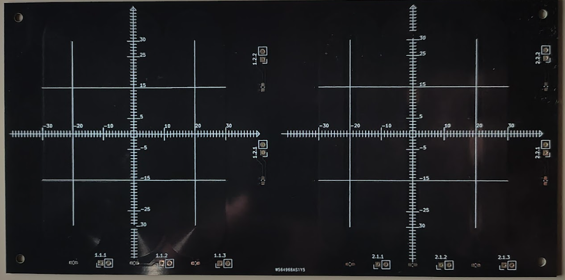
Here are the results:
Testing the Sensitivity
The big question about this side route is if we are going to be able to make enough change in the measured inductance that we can measure it well enough? Given that we have pcb coils, interviewing traces, and spherical target, instead of a flat one.
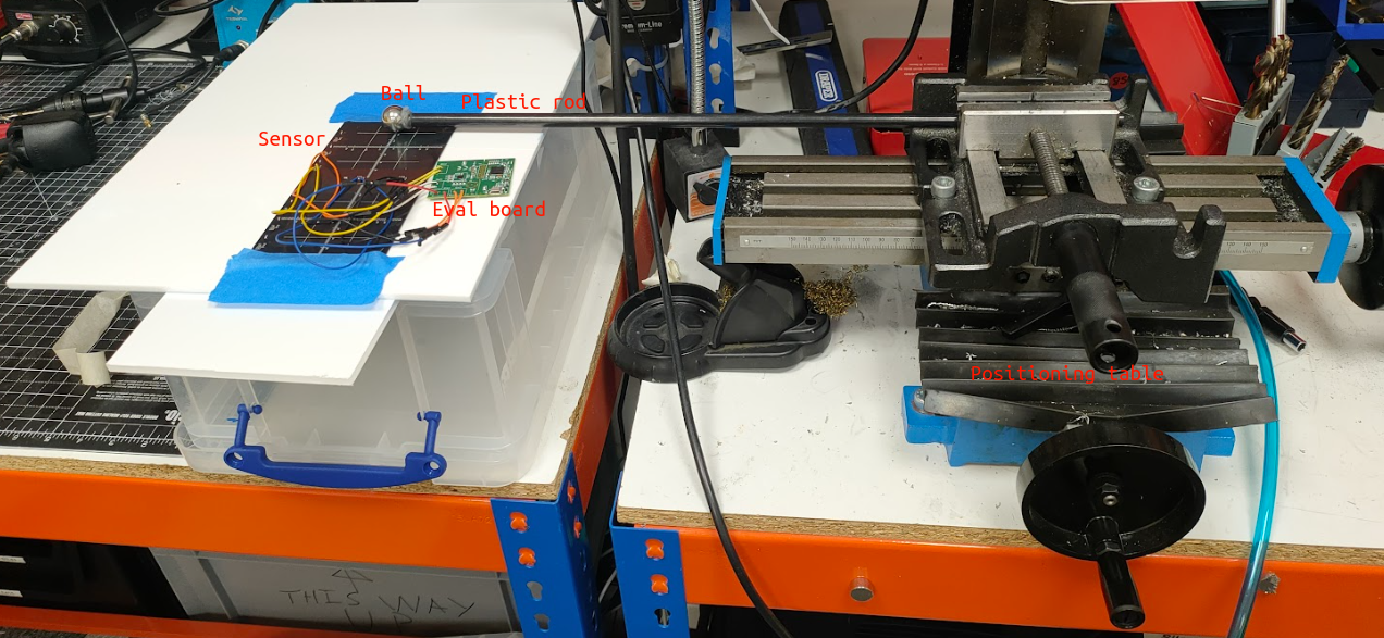
To test this I used the LDC1614EVM evaluation board and mounted the ball on a plastic rod, so it wouldn't interfere with the measurements. The plastic rod was fastened to an X-Y positioning table, that let me set the ball's position with sub mm accuracy.
After painstakingly taking a measurement at every single millimetre and manually recording the measured value, here is what we got:
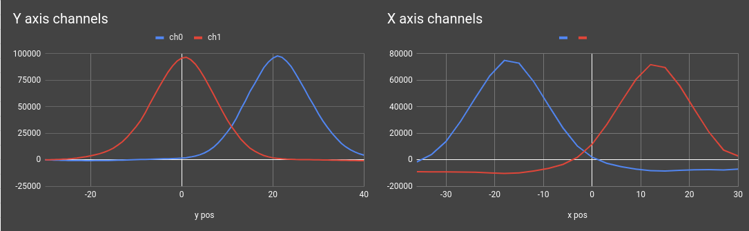
The results are promising. We are seeing a 100000 counts maximum activation on the Y axis channels, and around 75000 counts maximum activation on the X axis. With this level of resolution, i'm happy to continue exploring in this direction
Summary
In this log we've introduced inductive sensing as a potential alternative to capacitive sensing and I designed a PCB to test the theory out. So far the results look good, so in the next logs we will look into manufacturing the new plate.
Discussions
Become a Hackaday.io Member
Create an account to leave a comment. Already have an account? Log In.