 JP Gleyzes
The story
I have an old Trotec laser engraver which is almost totally dead:
- laser tube is almost blind
- software is using Windows95 OS
So more than 25 years later it was time to refurbish this machine.
- Changing the laser tube will be described into another project
- Changing the control board should be simple...FluidNC can drive any stepper board
So I opened the machine and very soon discovered that steppers motors were not "steppers" but DC motors with encoders... and a very specific electronics to drive them...
Here is the rotary axis of this Trotec machine when "opened"
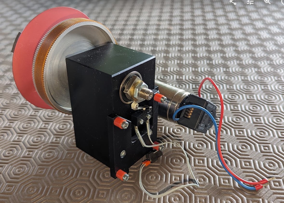
- on the right the DC motor
- on the end shaft of this motor is an optical encoder
- under the main shaft is a "home switch"
We will see how to reuse these elements to convert this motor into a stepper.
This mod will be demonstrated with this motor but will be generic enough to be applied on any other DC motor.
Main specifications are synthetised into this log
But let's start by a video showing the "final" product !
And a second one with this stepper (almost) installed into my Trotec laser. Control is still done by FluiNC and jogging done by gSender.
Before going further i must say that this controller will NOT act exactly as a stepper does.
I did mount two of these "pseudo steppers" into my CNC machine and added a pen plotter. Here is the result of what should have been a straight line at 45° in theXY plane (line x=y in cartesian coordinates)
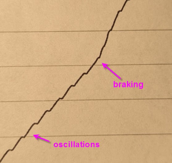
As you can see, oscilations are visible and the slope of the curve is not constant, we can clearly see when the braking is applied on one motor.
Consequently this controller is NOT suitable to precisely control a CNC. Despite the fact that the target position will be reached precisely, the motion itself is not linearly controlled. It is not a speed controlled PID. Furthermore the tuning of the PID will depend on the motor and two pieces (even from the same manufacturer) will not have exactly the same tuning...
This project is usefull to control position (number of steps) but not to control the speed to reach this position.
The DC motor driver
My motors are all 35NT2R_82_426SP ones. They are still manufactured by Portecap and have the following specs :
- 102 W,
- 32 V, --> power supply 24V
- 115 mNm,
- 5900 rpm,
- 3mm Shaft Diameter
To drive them I needed a driver able to sustain 24V and 4A
I chose the "IBT-2" one available on Aliexpress at very cheap price
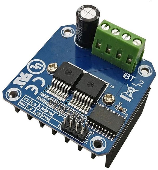
They are all equiped with a BTS7960 43A chip which is a dual H bridge with following specs:
- Input Voltage: 6 ~ 27Vdc.
- Dual BTS7960 H Bridge Configuration.
- Peak current: 43-Amp.
- PWM capability of up to 25 kHz.
- Control Input Level: 3.3~5V.
- Control Mode: PWM or level
- Working Duty Cycle: 0 ~100%.
- Over-voltage Lock Out.
- Under-voltage Shut Down.
So this driver is perfect for my setup. It can even be controlled by 5V or 3.3V logic MCU. An ESP32 will be perfect.
The encoder
Attached to the motor shaft is an optical encoder hedm-5500_J14 manufactured by Avago
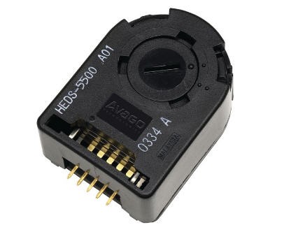
it has a Two channel quadrature output with a resolution of 1024 counts per revolution. It will be perfect to know precisely the shaft position.
Schematics
Here is the schematics of the driver board.
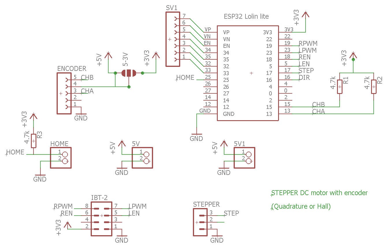
The heart of the system is a Lolin32 lite ESP32 board. And that's almost it !
You will find
- the encoder interface (5V or 3.3V if yours is more modern than mine)
- the Step/Dir connector
- input for the Home switch
Note that the encoder outputs need to be pulled up (CHA, CHB signals)
PCB
This schematics was routed into a tiny PCB which was kindly sponsored by PCBWay.
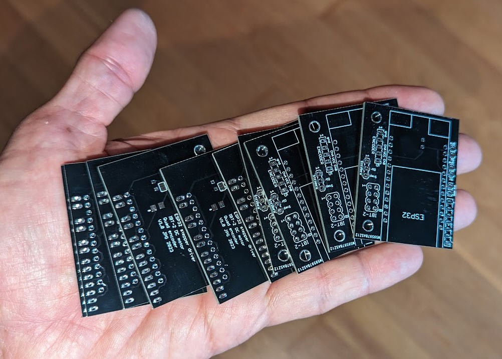
You can find it on PCBWay shared projects
Soldering this board is as simple as it could be. The result is a "mezzanine" board to put and screw on top of the DC motor IBT-2 driver.
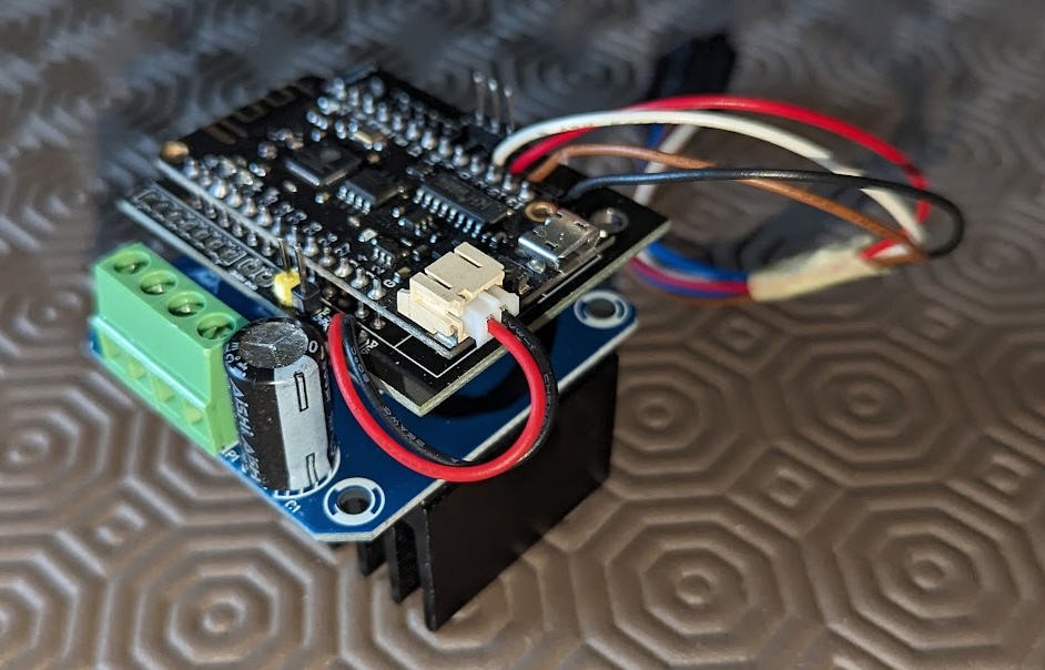
And here is the result into a small video :
Software
Software of this project is quite simple but rather "tricky".
We need to
- read the encoder
- read the "step/dir" signals to control the motor
- convert Step/Dir into motion and regulate this motion (acceleration, speed, start/stop)
All this should run as fast as possible to sustain high rate Steps coming from the CNC controler...
This is the reason why this code is using the two cores from the ESP32 and specialized hardwares embeded into the ESP32 as well as interrupts.
Source code is available into my Github pages.
Reading the encoder
A quadrature encoder is an incremental encoder with two out-of-phase output channels used in many general automation applications where sensing the direction of movement is required. Each channel provides a specific number of equally spaced pulses per revolution (PPR), and the direction of motion is detected by the phase relationship of one channel leading or trailing the other channel.
By chance the ESP32 has a special hardware named PCNT (Pulse Counter) which is totally adapted to decode quadrature encoders. The main interest is that it will be done by hardware and thus will not overload the MCU.
By chance also, a FastInterruptEncoder library has been writen by levkovigor
You will recognize into my code the ESP32 interrupt.ino example code. It is pretty simple to use but quite complex to understand.... Try to understand if you want !
#include "FastInterruptEncoder.h"

//Encoder enc(PA0, PA1, SINGLE /* or HALFQUAD or FULLQUAD */, 250 /* Noise and Debounce Filter (default 0) */); // - Example for STM32, check datasheet for possible Timers for Encoder mode. TIM_CHANNEL_1 and TIM_CHANNEL_2 only
Encoder enc(25, 26, SINGLE, 250); // - Example for ESP32

unsigned long encodertimer = 0;

/* create a hardware timer */
hw_timer_t * timer = NULL;

void IRAM_ATTR Update_IT_callback()
{
  enc.loop();
}

void setup() {
  Serial.begin(115200);

  if (enc.init()) {
    Serial.println("Encoder Initialization OK");
  } else {
    Serial.println("Encoder Initialization Failed");
    while(1);
  }

  /* Use 1st timer of 4 */
  /* 1 tick take 1/(80MHZ/80) = 1us so we set divider 80 and count up */
  timer = timerBegin(0, 80, true);
  /* Attach onTimer function to our timer */
  timerAttachInterrupt(timer, &Update_IT_callback, true);
  /* Set alarm to call onTimer function every 100 ms -> 100 Hz */
  timerAlarmWrite(timer, 10000, true);
  /* Start an alarm */
  timerAlarmEnable(timer);
}

void loop() {
  if ((millis() > (encodertimer + 1000)) || (millis() < encodertimer)) {
    Serial.println(enc.getTicks());
    encodertimer = millis();
  }
}
This code uses the PCNT device as well as one timer to allow access to the pulse count into the main loop.
Easy to use as I said:
enc.getTicks();
reading the "step/dir" signals to control the motor
I simply used an interrupt routine to triger edge processing on the Step pin
//stepper control


const int pinStep = 17;   // Steps input pin
const int pinDir = 16;     // Dir input pin

void IRAM_ATTR stepper_IT_callback()
{
  if (digitalRead(pinDir) == HIGH) targetRot += 5.12; //= 1024/200 ==> gives a 200 steps/turn stepper !
  else targetRot -= 5.12;
}
So targetRot variable should contain the number of steps ordered by the CNC controller.
What is this 5.12 trick... It's not a trick !
The encoder has 1024 pulse per motor revolution.
Standard stepper motors have 200 steps per turn... 1024/200 = 5.12 ... for any step required by the controller I must turn the shaft by 5.12 encoder pulses !
It's also a way to reduce the steps frequency and avoid to overload the MCU.
Bear also in mind that PCNT counter is able to detect both CHA and CHB signals on RIZING and FALLING edges. So that we already have not 1024 pulses per turn but 1024 * 4... We will see later how this is handled into FluidNC configuration. For the moment consider that we have a 200 steps motor driven with 4 microstepping.
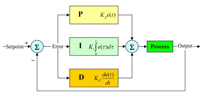
Controlling motor position and velocity
We will use a PID controller to control motor speed and position.
- input will be the nuumber of steps seen by the encoder
- setpoint the number of steps converted into encoder value required by the CNC controller
- output will be the Voltage to be applied on the motor which is the PWMvalue driving the DC motor driver
We will use the excellent PID library. (with a small modification explained later)
//PID
#include    //https://github.com/br3ttb/Arduino-PID-Library
double setpoint, input, output; //used by PID lib
double prevOutput;
//setpoint= nb Rotation of the motor shaft (expressed in encoder nb pulses),
//input = current rotation (expressed in encoder nb pulses),
//output is pwmSpeed of the motor

//Specify the links and initial tuning parameters
double Kp = .45, Ki = .01, Kd = 0.0002; //will be modified into the loop
PID myPID(&input, &output, &setpoint, Kp, Ki, Kd, DIRECT);  //declare the PID
Then into the setup we enable this PID
 //turn the PID on
  setpoint =  targetRot;              //setpoint is the number of turns on the motor shaft
  myPID.SetMode(AUTOMATIC);
  myPID.SetOutputLimits(-2047, 2047); //output of the PID is the pwm value. coded on 11 bits and forward/reverse
  myPID.SetSampleTime(40);            //compute the PID every 40µs (see timing into loop). Needs modified version of PID lib (micros instead of millis)
  Kp = .45;                           // start with a PID controller with very soft Kd
  Ki = 0.01;
  Kd = 0.0002;
  myPID.SetTunings(Kp, Ki, Kd);
Finally as fast as possible into the loop we compute the PID and use its output to drive the motor
 //PID stuff
  input = rawValue;
  setpoint =  targetRot;
  myPID.Compute();


  //DC motor driver
  pwmSpeed = output;  //use output of the PID to drive the motor
  runMotor();         //will apply direction and pwm value to the driver
driving the motor
This is quite simple, we simply generate a PWM on 2 pins that we apply to the DC motor driver
void runMotor(void)
{
  if (pwmSpeed > 0)
  {
    ledcWrite(0, pwmSpeed);
    ledcWrite(1, 0);
  }
  else
  {
    ledcWrite(0, 0);
    ledcWrite(1, -pwmSpeed);
  }
}
These PWMs are declared into the setup and do use Ledc function of ESP32 (hardware PWM)
 //IBT-2 DC motor driver
  pinMode(RPWM_PIN, OUTPUT);
  pinMode(LPWM_PIN, OUTPUT);
  pinMode(ENABLE_PIN_L, OUTPUT);
  pinMode(ENABLE_PIN_R, OUTPUT);

  ledcAttachPin(RPWM_PIN, 0); // assign PWM pins to channels
  ledcAttachPin(LPWM_PIN, 1); // assign PWM pins to channels
  // Initialize channels : ledcSetup(uint8_t channel, uint32_t freq, uint8_t resolution_bits);
  ledcSetup(0, 24000, 11); // 24 kHz PWM, 11-bit resolution (range 0-2047)
  ledcSetup(1, 24000, 11);
The IBT-2 driver accepts PWM frequency up to 25 kHz... reason why I chose a 24 kHz Pwm
The range of control will thus be 11 bits from -2047 to +2047
And now the tricky part... tuning the PID
tuning the PID
Tuning the PID is the way to find the optimal values for Kp, Ki and Kd terms.
There are several ways to this. I chose "manual" method. PLease read this excellent page to understand what a PID is doing: https://www.thorlabs.com/newgrouppage9.cfm?objectgroup_id=9013
The manual method starts by tuning the Kp term (Ki and Kd being both set at 0). Kp is directly proportionnal to the difference between command (number of steps converted into encoder count) and the result (effective number of pulses measured on the encoder sensor).
Basically you will have to increase Kp until you get some overshoot. Then you decrease it just before you get the targeted motion.
Then you will increase slightly Ki term. Ki gets the "memory of the past" and will allow to balance this permament error to achieve a perfect positionning on the targetted motion. Ki is an integral term which keeps track of all the cumulative errors got in the past.
Now you can increase very very slightly the Kd term. Kd, to a certain extend, will try to predict the future looking at the trend of increase (or decrease) of the signal : it's a derivative term extremely sensitive to noise...
Note that the tuning in my code has been done for these particular motors and should be redone for other types of motors.
Nevertheless tuning the PID should be done for all the range of speeds you want to use for your system. Verify that you get a proper motion at very low speed and up to the fastest speed you intend to use.
What is the fastest speed ? Well the answer is simple : it's when you apply the maximum voltage to your motor. And thus it is when you apply the max pwm value to your driver (+-2047).
So you should observe the output (logged into the serial monitor) of the PID (pwmValue) and verify that you get close to +-2047 but that you never get it. The reason being that if you get 2047 then your PID will saturate the output to the max value and thus will not regulate the speed.
A good value is a max output close to 1900-1950 to get a little margin for overshoot.
To help you tune your PID I have writen a small ESP32 sketch that you can compile and install on a second ESP32 board. It will emulate a CNC controller and move a single axis using AccelStepper library
All you have to do is to connect the Step (pin14) and the Dir (pin12) of this board to the PCB connector "Step/dir/ground". Both grounds of the boards must also be connected.
Then you launch both programs on the two boards and your motor will try to turn from one direction to the other.
I have captured the serial output and traced some graphics with Excel. Here is the result of a properly tuned PID:
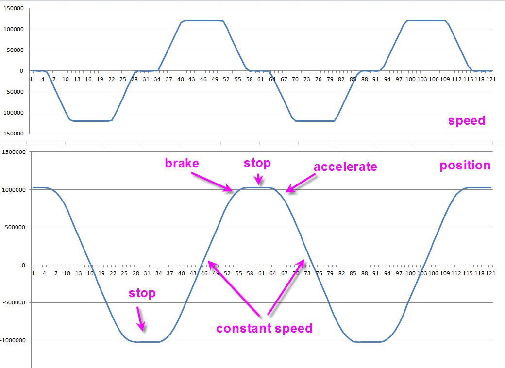
Two graphs are surimposed. top one is speed while bottom one is position (number of pulses seen by the encoder).
We can easily see the linear behavior of the motion when motor is at constant speed and the stop condition when motor is (almost) at zero.
A few more tricks
The PID library allows to set the wakeup period when the PID is computed.
If you look at my code you will find this line
myPID.SetSampleTime(40); //compute the PID every 40µs (see timing into loop). Needs modified version of PID lib (micros instead of millis)
The original PID library allows to compute PID down to every 1ms
As we use this lib on a powerful ESP32 we can handle a much faster response time. I have measured the maximum time spent into the main loop. It is 35µs. And this time is mostly eaten by the PID library.
So I have modified this library to allow to set the "SampleTime" using microseconds (40µs) instead of milliseconds (1ms). You can find this modified version also into my github pages.
Doing this mod allows a much faster response time of the system (40µs), limits oscillations and allows a much smoother behavior.
Another "trick" is to limit at the maximum the time spent into the main loop. This insures a consistant compute time and prevents oscillations or glitches of the PID. This is the reason why you MUST avoid to use "Serial.print" into the loop (or any other not needed long processing job).
If you want to use "Serial.print" into your code, limit them at the maximum and deport them into the core1 Task
//multitasking
TaskHandle_t Task1;

#define CLOCK_PERIOD 500

void core0Task1( void * parameter )   //this task will run for ever on core 0
{
  for (;;)  //put here code that could otherwise slow core1 loop...
  {
    delay(CLOCK_PERIOD);
    Serial.print("pos pwm\t");
    Serial.print(rawValue);
    Serial.print("\t");
    Serial.println(pwmSpeed);
    //    minimum = 1000000;
    //    maximum = -100000;
  }
}
And a last trick : managing motor deadband...
You will very fast discover that the PID will "slow down" the motion as soon as you get close to the command. This is a normal behavior but has a major drawback for a servo motor: when you are close to the targetted position the PID will output a very small voltage... not enough to move the motor or to keep its position.
A solution is to handle a "Deadband" where you superseede the output of the PID. This is a simple but efficient process that you will find into these lines of code:
myPID.Compute();

  if (abs(output) < DEADBAND)
  {
    if (output > 5)         output += DEADBAND ;  //go on moving with enough power
    else if (output < -5)   output -= DEADBAND ;
    else                    output = 0;           // between -5 to +5 do not move
 }
It's easy to understand. This code "skips" the deadband and keeps the motion close to when the motor starts to move.
To tune it, simply increase the DEADBAND parameter when the motor is stopped until it starts to "vibrate". Don't go too high or oscillations will be seen, nor too low where you will feel that the motor is getting too smooth when stopped.
You have now a fully tuned PID.
Try to do this procedure, and advantages of a closed loop system will become obvious compared to open loop stepper motor :
while stopped try to move the rotor manually: it will react, the more strenght you apply on the shaft the more the PID will increase voltage on the motor to counterbalance this motion. Release your pressure and the shaft will recover its commanded position.
Do the same with a stepper and you will skips steps... for ever, without even knowing it !
Is your motor really like a stepper ?
To answer this difficult question we will try to use the motor with a CNC controller.
Today's best choice is obviously FluidNC. FluidNC runs on ESP32 and has been fully optimized for this MCU. Furthermore it's free and open source!
Installing FluidNC
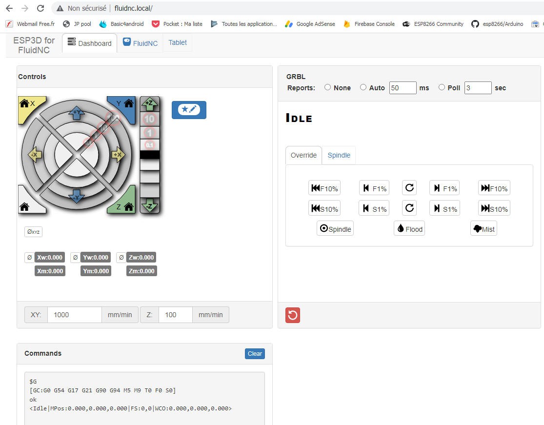
Here is FluidNC's simple interface to pilot your CNC. We will try to use it to pilot our "pseudo stepper"
First thing to do is to install Fluidnc on a brand new ESP32. This is explained into this log.
Connect the controller to your "stepper"
Simply connect pins 12 and 14 from your FluidNC ESP32 to the "Step/Dir/gnd" connector of the "stepper."
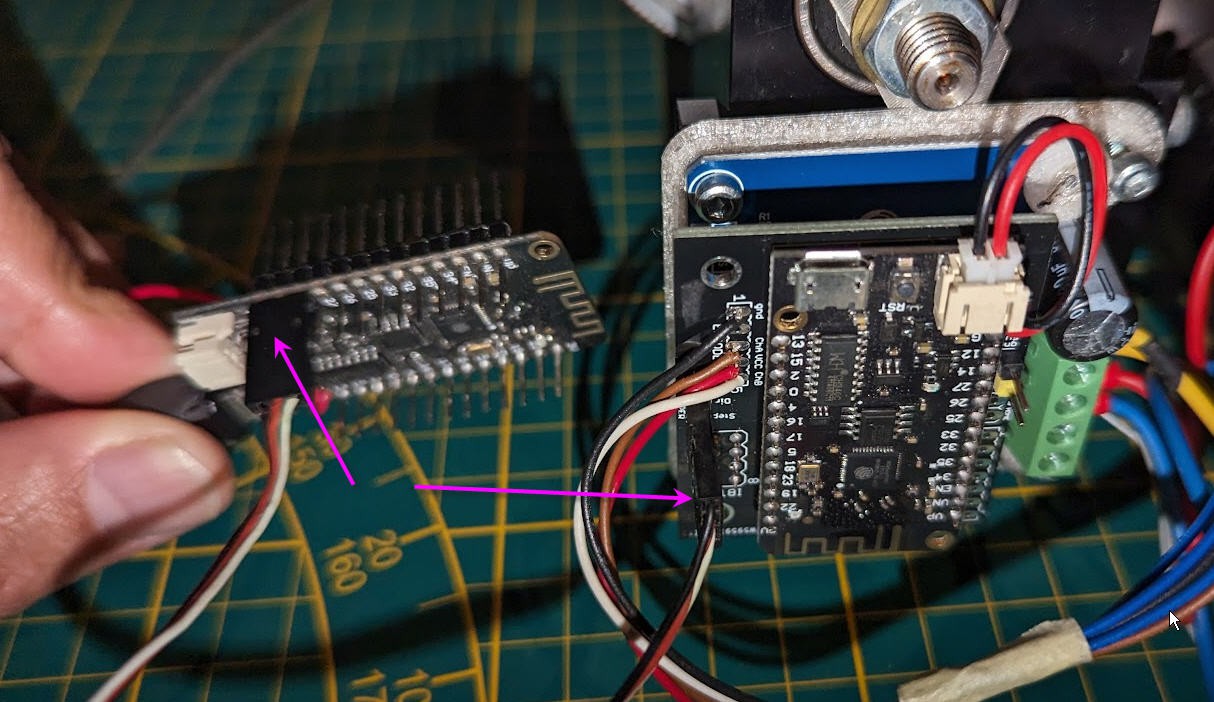
And power both boards with 5V (you can safely do it via their USB connectors).
Don't forget to power the driver with the stepper power supply (mine is at 24V)
And you can jog your new CNC with the X axis buttons
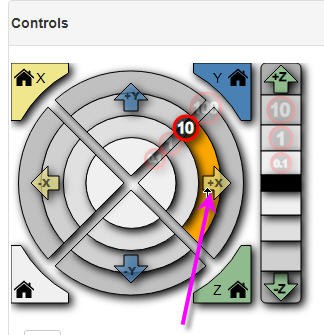
Change the "feedrate" to slow down/increase your motion speed
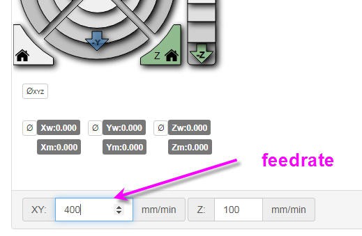
Fantastic your stepper moves like a stepper. FluidNC is able to control not only its position but also its speed.
Exactly what we were looking for.
and here is again the result :