Florian Wilhelm Dirnberger
1. Description
The concept of this radio frequency detector (originally advertised as "Radar Detector") is anything but new, and schematics with the LM1458 op amp are floating around in books and on the internet for decades.
Yet barely anyone ever seem to have actually built this particular device so I decided to test whether it is a viable design (it is, sort of).
2. Schematic
Capacitor C1 is the determining part here. Shortening its pins may or may not increase the performance drastically. The value itself is apparently not so very important (should be in the nF range though).
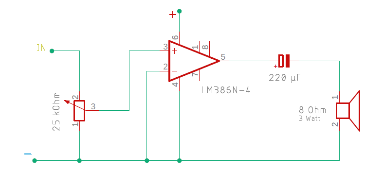
One can connect a LM386 amplifier and a Speaker at the OUT Pin for an immediate feedback (below is a further schematic), but maybe you guys have a better suggestion what to do with the output signal (see example oscillogram photo).
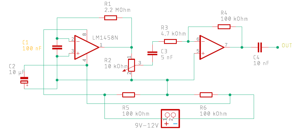
The first op amp stage together with the two 100k resistors resemble a supply splitter (what makes sense for we supply the detector with a 9V battery, not with a symmetrical voltage), the second is an inverting amplifier.
C3 and C4 provide capacitive coupling.
3. Demo video
Tests with various radio frequency emitting items, such as a Raspberry Pi Pico W, a Bluetooth Low Energy module, and a mobile phone.
4. "Radar detector"
Military and civil radar operates (or used to operate) also in the lower GHz regions (L-Band, S-Band, etc.). Example: Airport Surface Detection (X-Band).
So it would be possible to detect these high frequency sources with this device, at least in principle (haven't tested that yet).
5. Sound generator
For the Speaker variant, the following set-up with LM386 can be used. The generated sound doesn't have to be pleasant, just loud enough to be heard, so we can ignore most of the design guidelines as to the LM386 IC.