 _electroidiot
1st Preamp Stage
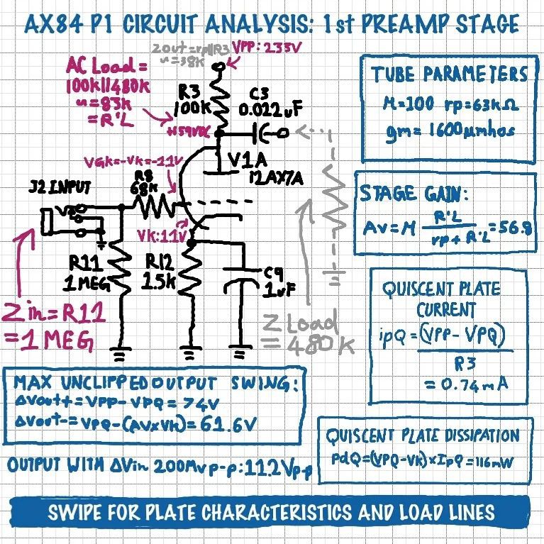
The AX84 uses just two tubes, a 12AX7/ECC83 and an EL84. But since the former is a dual triode, there are three tube stages in total. Let's see what we can work out about the first half of the 12AX7, which serves as the input stage, using the component values and voltages given on the schematic.
• Input Impedance – Since the grid doesn't draw any current, Zin = R11 = 1 Meg.
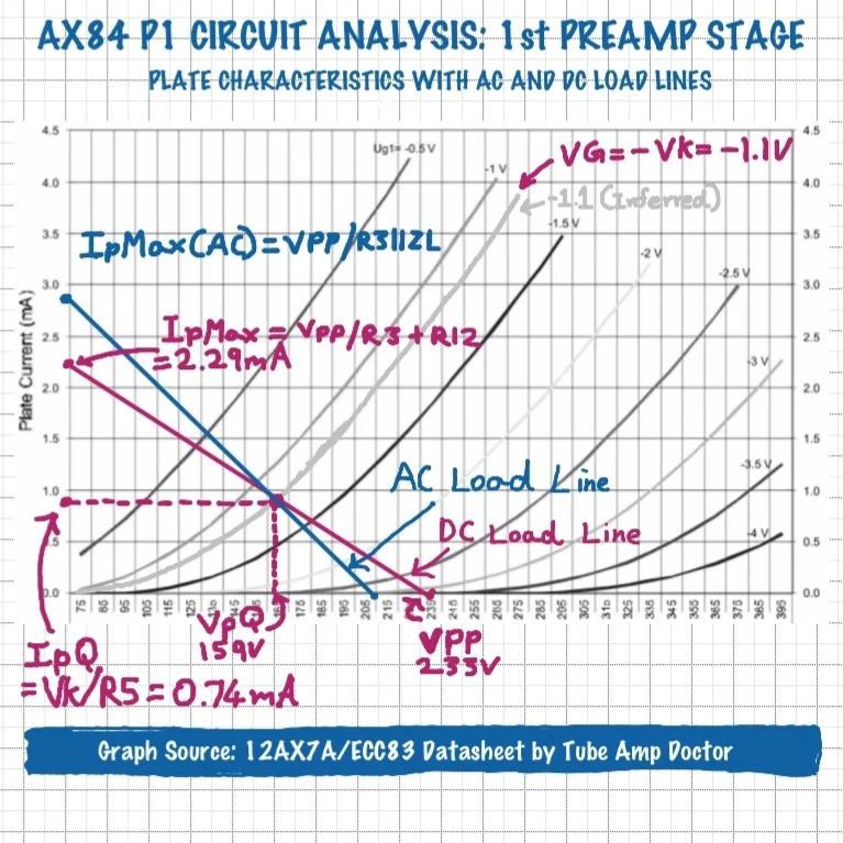
• R8 is a grid leak resistor which forms a low pass filter with the parasitic capacitance of the grid, in order to prevent oscillation and RF interference.• Quiescent Plate Current – ipQ = (VPP-VPQ) / R3 = 0.74mA
• Quiescent Plate Dissipation – pdQ = (VPQ-Vk) × ipQ = 116mW• Equivalent AC Load Resistance – R'L = R3 || Zload = 83K, where Zload is the approximate input impedance of the next stage.• Voltage Gain – Av = Mu × (R'L/rp+R'L) = 56.3. For reference, this would mean that ∆200mV at the Input would results in ∆11.2V at the output.
• Maximum Positive Output Swing Before Clipping – ∆Vout+ = VPP - VPQ = 74V.
• Maximum Negative Output Swing Before Clipping – ∆Vout- = VpQ - (Av × Vk) = 61.6V. This is because once the positive input swing overcomes the negative grid bias, the grid is driven positive causing soft clipping.• Output Impedance – Zout = rp || R3 ~= 38K.
2nd Preamp Stage
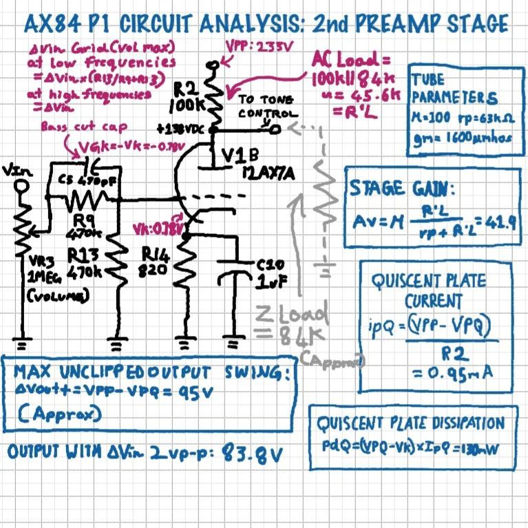
The other half of the 12AX7is used as another common cathode gain stage, similar to the first. However, there are a few differences.
• The output of the first stage is fed to a 1 Meg logarithmic pot for volume control.
• C5 and R9 form a frequency dependent voltage divider along with grid resistor R13. This is done to attenuate low frequencies, thus C9 could be called a bass cut capacitor. Basically, C9 appears as a short to high frequencies, making the whole input available at the grid, but at lower frequencies it appears as an open, causing those frequencies to be attenuated by the R9 R13 voltage divider. If C9 and R13 are seen as a high pass filter, the 3dB point works out to be around 720Hz.
• Input Impedance – The input impedance varies based on the position of the volume control and the signal frequency. When the volume is at maximum, and the frequency is High enough that C9 appears as a short, we can approximate Zin = R13 = 470K.
• Quiescent Plate Current – ipQ = (VPP-VPQ) / R2 = 0.95 mA.• Quiescent Plate Dissipation – pdQ = (VPQ-Vk) × ipQ = 130mV.
• Equivalent AC Load Resistance – R'L = R2 || Zload = 45.6, where Zload is the approximate input impedance of the tone stack. More on that in part 3!Voltage Gain – Av = Mu × (R'L/rp+R'L) = 41.9. For reference, this would mean that ∆2V at the grid would result in ∆83.8V at the output.• Maximum Positive Output Swing Before Clipping – ∆Vout+ = VPP - VPQ = 95V.
• Maximum Negative Output Swing Before Clipping (approximate, since the plate curves get very non linear towards saturation) – ∆Vout- = VpQ - (Av × Vk) = 105V.• Output Impedance – Zout = rp || R2 ~= 38K.
Tone Controls
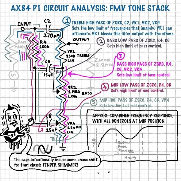
The AX84 uses a variation of the classic FMV tone stack. This is a circuit that many people struggle with, but let's see if we can make sense of it.
Essentially, the FMV stack is a combination of 5 filters that are all interdependent on each other. The filters output certain frequency ranges to the "stacked" treble, bass, and mid pots which are used to attenuate the various signal outputs as well as alter the response. The filters can be broken down as follows:
• The high pass of Zsrc, C2, VR1, VR2, VR4 sets the low limit of the treble control. Treble pot VR1 blends the outputs of the treble filter and the bass and mid pots, feeding the signal to the next stage. Note that Zsrc is the preceding stage's output impedance. It is not strictly a part of the tone stack, but I have chosen to include it as it has a considerable effect on the filters' frequency responses.
• The low pass of Zsrc, R4, C6 affects the high point of the bass filter's response. Interestingly, this point is out of the guitar's frequency range, so the "slope" of the filter is the actual bass response that we get.
• The high pass of Zsrc, R4, C6, VR2, VR4 sets the low limit of the bass filter. This 3dB point falls below the audio frequency range!• Low pass of Zsrc, R4, C8 affects the high limit of bass control.
• High pass of Zsrc, R4, C8, VR4 influences the low end of the mid control.
Rob Robinette has a great article on his website about the FMV tone stack, and he has mentioned the 3dB points of the various filters. However I found that it is difficult to correlate the 3dB points to the actual combined response. This is because the filters are highly interdependent and appear in various series and parallel combinations to each other, making mathamatical analysis of the circuit ridiculously complex. DeepBlueHarp on YouTube has some good videos going into some detail, but honestly, I feel that this a circuit best understood intuitively instead. Note the "scoop" in the overall response. This is done intentionally to compensate for the elevated mid-range of most guitar pickups. Duncan's Amp's has a great computer program for graphing the frequency responses of various types of tone controls. I have included screenshots of the program showing the AX84 tone stack's response at various settings. Another important aspect of the circuit is the phase shifts it induces. This causes a shimmering sound which that is often associated with classic Fender amps. Also, the original Fender circuit had VR4 wired as a variable resistor. This would cause the amp to go silent when all the tone controls are set to minimum. In the AX84, VR4 is wired as a potentiometer as in the Marshall version of the stack. The input impedance of the tone stack too varies based on frequency and potentiometer positions, affecting the preceding stage's gain. The above is what I understood about the circuit after going through various sources. There are a lot of discrepancies in various descriptions of the circuit online, so I cannot say that my understanding is 100% accurate either. I think that the esoteric nature of the FMV tone stack is yet more proof that Leo Fender was literally a genius.
Output Stage
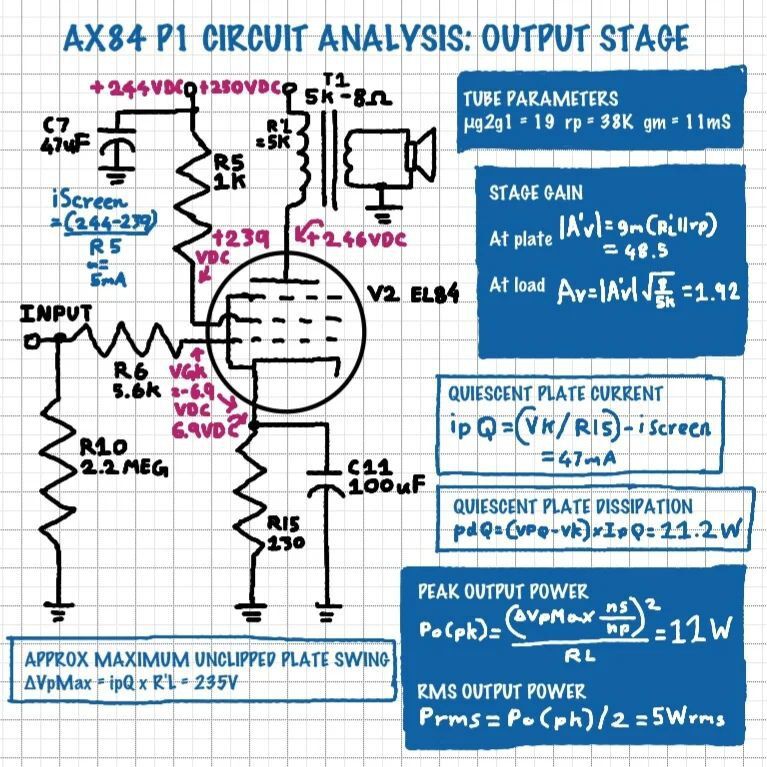
The last tube stage's primary job is to provide the power to drive our speaker. While the preamp stages are designed to step up the signal voltage, the output stage is more focused on current gain.
• The output of the tone stack is fed to the EL84's grid via grid snubber resistor R6.
• The input impedance is equal to R10, or 2.2 Meg Ohms.• Quiescent Plate Current – ipQ = (Vk/R15) - iScreen = 47mA, where iScreen is the screen current.
• Quiescent Plate Dissipation – pdQ = (VPQ-Vk) × IpQ = 11.2W.
• Equivalent AC Load Resistance – R'L = Zload × T1 Turns Ratio^2, since Impedance varies with the square of the turns ratio. The output transformer T1, reflects the 8 ohm speaker Impedance as 5K ohms to the EL84's plate.
• Voltage Gain at Plate – |A'v| = gm(R'L||rp) = 48.5.• Voltage Gain at Load – Av = |A'v| × √(8/5K) = 1.92. Note that T1 steps down the voltage delivered to the speaker, but steps up the current.• Approximate Maximum Output Swing Before Clipping – ∆VpMax = ipQ × R'L = 235V.
Note that since the plate is operating into a reactive load, the actual plate voltage can exceed B+. When plate current decreases enough to counter the bias thus causing the grid to go positive, the CHANGE in plate voltage will be as mentioned. This can be inferred more accurately using the plate characteristics curves, but I could not find any for a screen voltage of 239 or 240V.
• Peak Output Power – Po(pk) = (∆VpMax × turns ratio)^2/RL = 11W. where the turns ratio is the square root of the impedance ratio of T1, and RL is the speaker Impedance.• RMS Output Power – Prms = Po(pk)/2 = 5.5Wrms.
Discussions
Become a Hackaday.io Member
Create an account to leave a comment. Already have an account? Log In.