 dhrumil
In embedded systems, any ESP32 development board is a formidable platform for developers and enthusiasts alike. But what if we told you there's a way to enhance the programming experience, eliminating the need for cumbersome cables and providing the freedom to move around while you work? WiSer allows you to program any ESP32 Development Board wirelessly over a serial interface. In this comprehensive guide, we'll walk you through the steps, showcasing the programming ESP32-S2 DevKit-M1 wirelessly using WiSer devices.
Personally, it proved beneficial when your embedded board (in this case, the ESP32S2 DevKit-M1 board) is placed in a lab with a hazardous environment, and you want to debug the dev board from your work desk wirelessly without any issues.
Additionally, wireless debugging implies complete electrical isolation from the board, ensuring the protection of your host system while debugging the board.
Understanding the Components
Before we begin on the programming journey, let's familiarize ourselves with the key components:
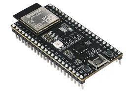
- ESP32-S2 DevKit-M1: A powerful and versatile development board based on the ESP32-S2 chip.
![]()
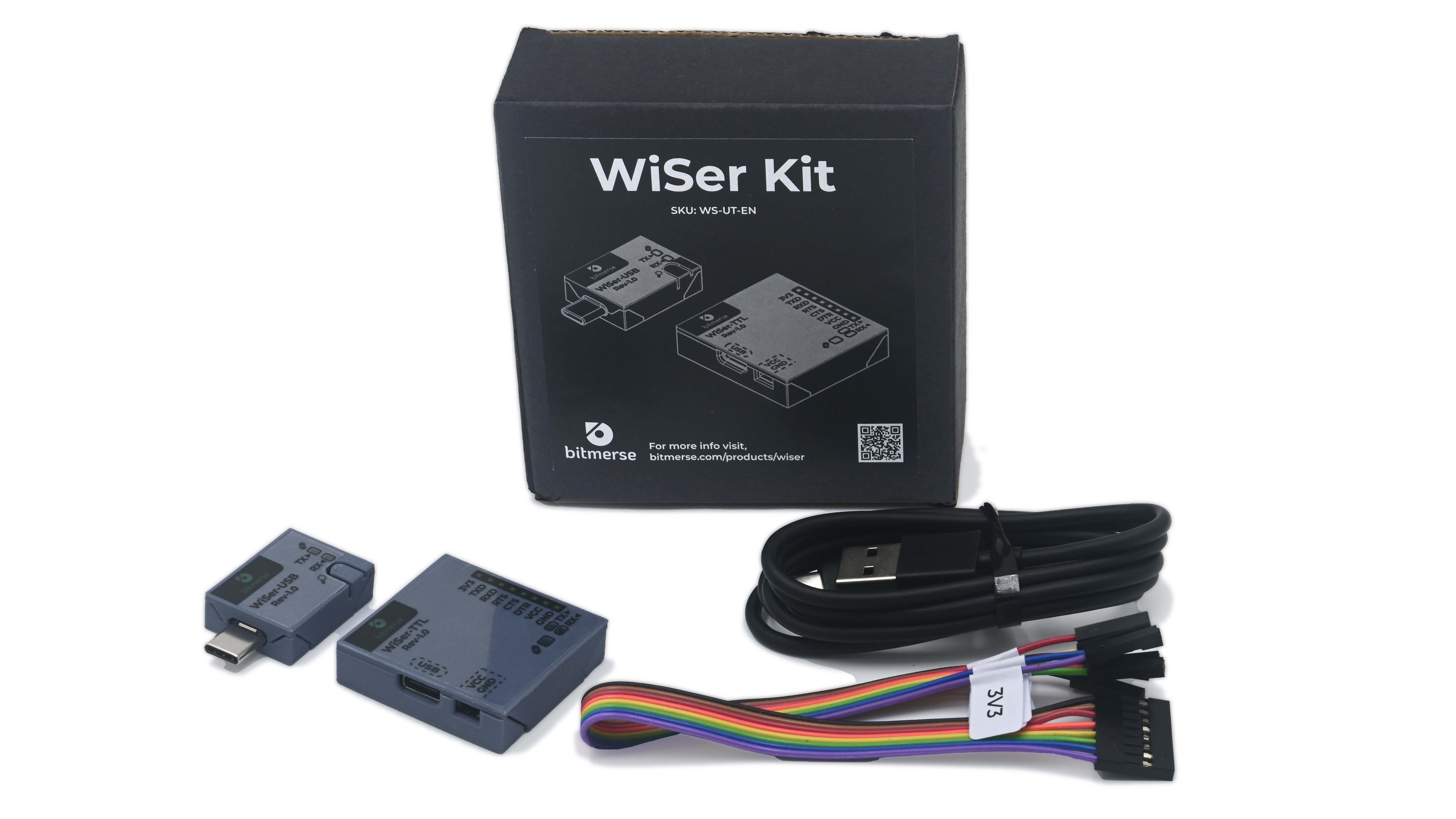
- WiSer Devices (SKU variant WS-UT-BM or WS-UT-EN): Consisting of WiSer-USB and WiSer-TTL, these wireless serial devices will serve as your programming bridge to the ESP32-S2 DevKit-M1. For more information about WiSer SKU variants, please visit WiSer Product Manual.
![]()
Prerequisites
- Get the ESP32-S2 DevKit-M1 development board.
- Ensure you have a sample example firmware for ESP32-S2 DevKit-M1. We are going use Blink example firmware in Arduino.
- Arduino IDE on Windows 10 PC or Mac with the added support of ESP32S2 Dev Module from Board Manager. Here, we are going to use Mac PC.
- Acquire a pair of WiSer devices. The WiSer-USB connects to your PC, while the WiSer-TTL interfaces with the ESP32-S2 DevKit-M1.
Step-by-Step Programming Guide
Step 1: Connect WiSer Devices
- Plug the WiSer-USB into an available USB port on your PC.
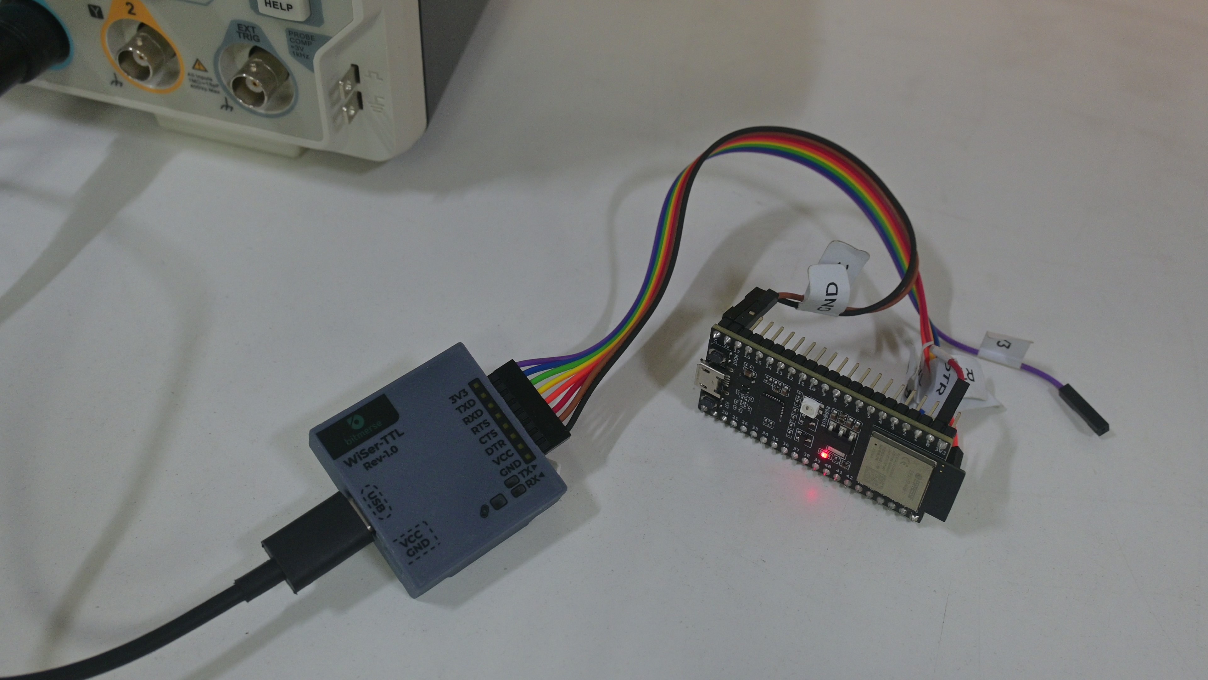
- Connect the WiSer-TTL to the ESP32-S2 DevKit-M1 as shown in the image. If you opt for an assembled WiSer-TTL variant, use jumper cables for a hassle-free connection.

Step 2: Power Up the Devices
- Power up the ESP32-S2 DevKit-M1 using a suitable power source.
- Ensure the WiSer devices are powered on. We are providing power to WiSer-TTL device through Type-C USB connector.
- In this case, we are providing power to the ESP32-S2 Devkit-M1 from WiSer-TTL by connecting VCC line of WiSer-TTL to 5V input line of the dev kit.
Step 3: Identify Paired WiSer Devices
- If you don't have multiple WiSer devices or you already know the paired WiSer-TTL device, then you can skip this step. To ensure our WiSer-USB and WiSer-TTL devices are paired with each other, short press the 'Find Pair' button on the WiSer-USB. The CONN LEDs on both paired devices will illuminate steadily for 5 seconds.
- This step helps you confirm the pairing between WiSer-USB and WiSer-TTL, especially useful when managing multiple WiSer pairs.
Step 4: Put ESP32-S2 DevKit-M1 into Bootloader Mode
Arduino IDE uses the RTS and DTR to reset and hold GPIO0 in order to put the esp32S2 Dev Board into bootloader mode.
- Verify the connection of required lines to program the board as shown in the table below.
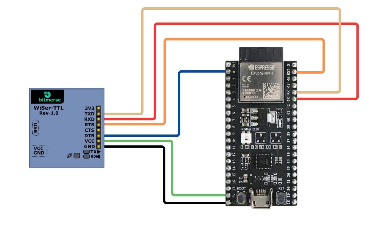
| WiSer-TTL | ESP32S2 DevKit-M1 |
| RXD | TX (J3 - Pin 6) |
| TXD | RX (J3 - Pin 5) |
| RTS | RST (J3 - Pin 2) |
| DTR | 0 (J1 - Pin 2) |
| GND | G (J1 - Pin 21) |
| VCC | 5V (J1 - Pin 20) |
- Ensure the RTS/CTS hardware flow control is disabled on WiSer devices. To do so, long press the 'Find Pair' button on the WiSer-USB for more than 2 seconds. The CONN LEDs will flash slowly, indicating that RTS/CTS hardware flow control is disabled. For more information about 'Find Pair' button go through the overview of WiSer devices.
Note: In the case of other MCUs that are not using RTS and DTR lines to switch into the Bootloader mode, you don't need to connect these lines. Please refer specific MCU's manual for serial interface connections.
Step 5: Flashing Firmware
- With the ESP32-S2 DevKit-M1 powered on, use your preferred firmware flashing tool (such as esptool command line, PlatformIO, or Arduino) to upload the firmware wirelessly. We are using Arduino IDE here.
- The WiSer devices act as a bridge, facilitating the seamless transfer of firmware from your PC to the ESP32-S2 DevKit-M1.
Step 6: Complete the Process
- Once the firmware is successfully uploaded, Arduino IDE will reset the board in Application mode using RTS line.
- Verify that the user LED is blinking on the ESP32-S2 DevKit-M1 board.
Congratulations! You've just programmed the ESP32-S2 DevKit-M1 using the WiSer devices. This wireless approach opens up new possibilities for debugging, testing, and deploying your ESP32 projects. We can even program or update the firmware of any embedded product board which allows programming/updating the firmware over the serial interface.
Discussions
Become a Hackaday.io Member
Create an account to leave a comment. Already have an account? Log In.