 Tony Robinson
This log is redundant - there is a complete Full Adder which uses this circuit at https://hackaday.io/project/160177-alu-in-dctl-technology/log/150451-full-adder and that work predates this and is more complete.
But, for the sake of not deleting valuable comments below, here it is (for now).
Addition can be decomposed into a carry chain (see past and future logs) and a three input exclusive OR operation which takes the two external inputs and the carry and produces the result.
https://hackaday.io/project/8449-hackaday-ttlers/log/150147-bipolar-xor-gate-with-only-2-transistors is the place to start for all things XOR. I'm just cascading two XOR in the same way as https://hackaday.io/project/160177-alu-in-dctl-technology/log/150451-full-adder and tweaking a few things.
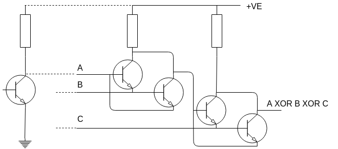
The left hand side a typical BJT set up, some current sets a bipolar transistor to conduct or not, in which case either A is near ground or is wired to the +ve supply via a resistor. I've put it in to show that this is the input we need and also because it was what was needed to help me understand what is going on.
The output has the same characteristics as the left hand side, it's either to ground via a couple of BJT or to +VE via the resistor. I used 330 Ohm resistors, these being slightly faster than 10k. The BJTs are 2N3904s. Currently I'm getting just over 500 kHz, which is good enough.
Discussions
Become a Hackaday.io Member
Create an account to leave a comment. Already have an account? Log In.
This 3-input XOR is exactly the same as formed by transistor T5, T6 and T10, T11 in my article https://hackaday.io/project/160177-alu-in-dctl-technology/log/150451-full-adder !
Are you sure? yes | no
It is indeed! Sorry not to have credited you, I got busy in 2018 and missed your article. I'm not sure what the best thing to do is, I'll either edit to give you credit or perhaps just pull the lot as it's not adding anything new. Probably the latter.
Are you sure? yes | no
No problem Tony, just leave the article as it is. I'm sure I'm not the first one to have thought of this.
Are you sure? yes | no
The cascadable Full Adder is ok for a few bits, other faster structures become necessary when the width increases.
Are you sure? yes | no
Well I do have a diode carry chain. Wikipedia says that Schottky diodes have "very fast switching action", I've yet to get it working though. Keeping the component count low is vitally important to me, it's a 16 bit adder so complex look ahead circuitry would dominate the whole computer and I'll never build it.
Are you sure? yes | no
If done correctly, a 16-bits adder is not /that/ large. It's just a matter of finding the right macro-structure and replicate it :-)
Are you sure? yes | no
Spice says about 5us with 10K and 2n3904 at 5 volts.... Resulting in a nice 01101001 sequence at the output for a binary count from 000 to 111 at points A,B and C.
Are you sure? yes | no
The resistors can easily be decreased to 1K or 470 for a bit more quickness :-D
Are you sure? yes | no
I'm pleased to see it running at slightly under 400 kHz (I'm running on 3.3V, which means less charge stored on the BJT). I shall tweak resistors and see how it goes.
Are you sure? yes | no
Awesome !
Are you sure? yes | no