 Ace
AceE-Papers are little odd. The bi-stable nature, which basically means these displays only needs power to change the content of the display, but no power is needed to retain it. Therefore, you can display an image, remove the power plug or battery, but the image on the display wouldn't change. Over time, in the wrong conditions (e.g. sunlight exposure, storing vertically), the contents may fade, however, that is a side-effect of using these displays. However, to even get an image on the e-paper itself, a e-paper specific driver board is required:
Thankfully, e-Paper displays use SPI for communication, meaning many boards and chips already support this feature. But it's not as easy to simply connect the SPI pins to the board, as these displays, apart from data, also require a higher voltage e.g. 15V in certain pins, while the SPI-pins require 3.3V. There must be a reason why the current non-official "golden standard" of SPI e-paper displays uses 24 pins instead of 6 (4 for SPI, + GND + 3.3V). Many of these pins basically require the additional voltage boosters, hence the need for a driver board.
It turns out, e-Paper displays require 2 additional pins (busy and reset), summing a total of 8 pins from the driver board to the board. The 24-pin flex-cable with 0.5mm pitch coming from the display may have contacts facing up or down, depending on the display, but a good driver board is still compatible with the flex-cable facing up. There seems to be a pattern: Placing the display with the display side facing up and connecting the flex-cable to the driver board will work in most, if not all cases.
Furthermore, even 24-pin 0.5mm pitch spi e-paper displays may use either 4-line SPI or 3-line SPI, depending on the integrated COG (chip on glass). Fortunately, most e-paper displays now use the 4-line SPI mode, so that can be simplified.
Last but not least, some displays require a certain resistance on one of the pins (0.47 Ohms) while others require a different resistance (3 Ohms) in order to work.
Now that we know that we need a driver board, we can look for it. Fortunately for us, there are many driver boards already available e.g. from Waveshare or Gooddisplay, even Adafruit.
Let's summarise what a good driver board should be able to do:
- drive the e-paper display
- Support both resistance versions of 24-pin SPI displays (0.47 Ohm and 3 Ohm)
- be small enough to fit inside most frames (max. height should not exceed 5mm)
- Not have any additional components to reduce power usage
- Should be available for a long time
- ideally components should only be on one side (top or bottom)

Let's start with the most famous one, from Waveshare:
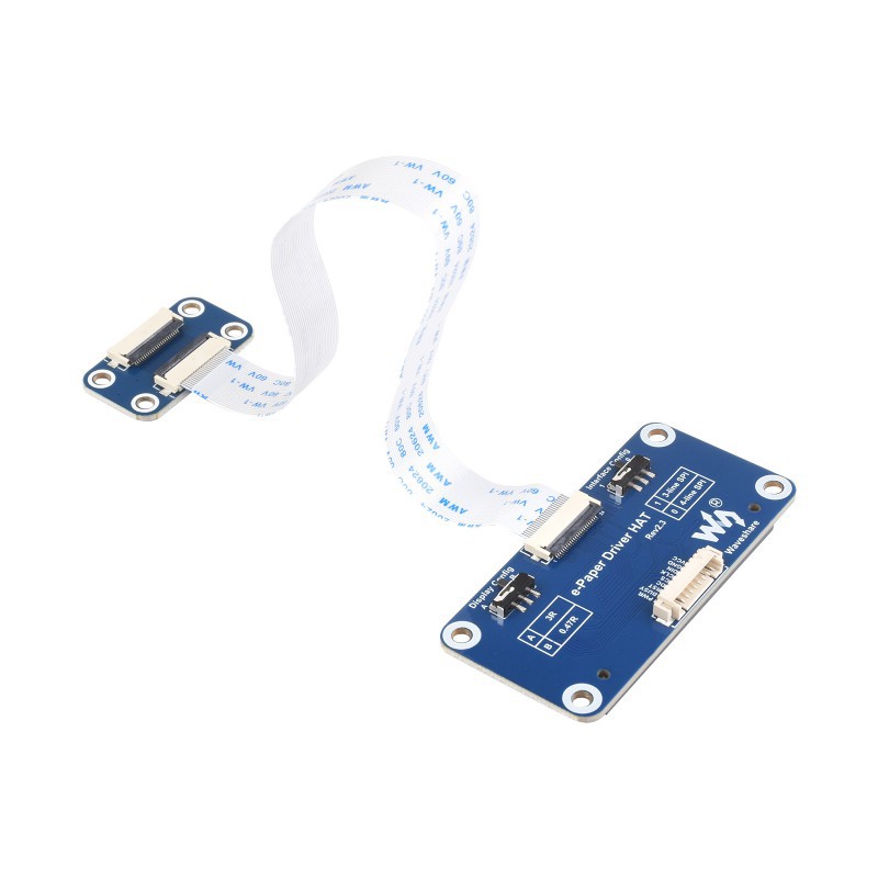
You can see two slide switches responsible for each of the config (3-line SPI or 4-line SPI), 0.47Ohm or 3 Ohm. However, as this is made into the hat form factor, it is simply too big as a driver board for any product you want to hide the electronics inside. Furthermore, even when used as intended on a Raspberry Pi, the placement of the connector on this driver board makes it difficult to even connect a larger display directly. As a result, they added an extension flex-cable and an additional pcb. Large flex-cables should generally be avoided as the buildup of forces inside them, without adequate shielding (e.g. metal foil), can affect the resulting image on the e-paper. That makes this board not so ideal.
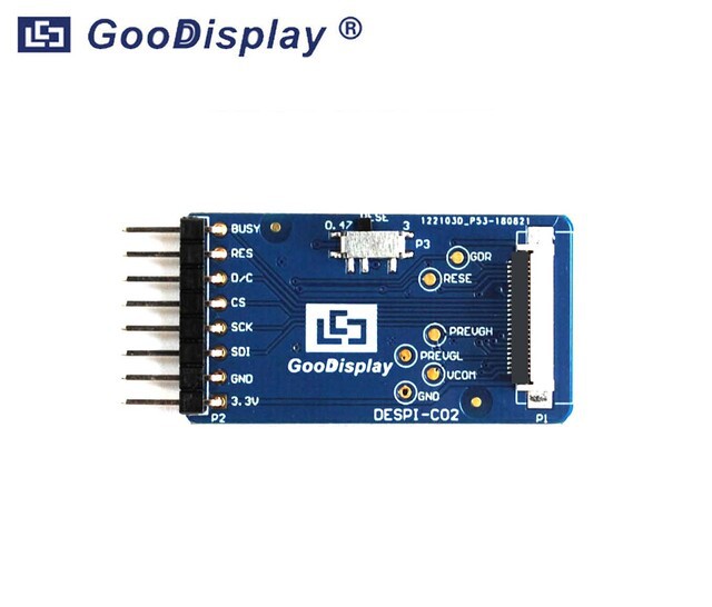
The next candidate is the Gooddisplay driver board. It is definitely small enough and contains only one slide switch instead of two, because most e-paper displays nowadays require setting only the resistance, not the SPI mode. This has been my favourite for a long time, however there was a catch. Most of the circuitry is on the bottom side while the connector, slide-switch and headers are on the top side, meaning it cannot be firmly glued to any surface. Also, with the headers already pre-soldered, it makes it a little difficult to deal with since you now have an elongated driver board, making placement of your own board a bit of a challenge in a constrained place. Then there was the delivery cost (and time) on top of the slightly expensive driver board itself, making this only a semi-viable option.
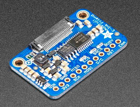
The third driver board was from no other than Adafruit. Little did I know for a long time they were in the e-paper business. But they have several products and developed their own driver board too. This small board was smaller than both the other solutions, however, the additional components, including SRAM which is too small for any larger e-paper display and logic level shifting increased the final price and the current consumption when the display was not in use. During covid, this board was hardly available anywhere as the additional ICs meant it was dependent on the availability of the required chips. Last but not least, one small but considerable thing I noted was the sliding connector. For anyone who has used with flex-cables before, these are difficult to use and in some cases can break easily. There are other options too, like the latching connector, but this was not being used here. However, overall this has been my favourite candidate for a long time too.
After working with these driver boards, sooner or later, I would be required to use a custom driver board, specifically designed for Inkycal, but yet being universal. After spending countless hours and after many failures and mistakes, I finally managed to design a fully working driver board, which was slim, small (even smaller than the Adafruit one), did not have any additional components to save costs. I personally like the contrast between dark blue and gold, similar to Adafruit, so it's pleasing to look at. It also has mounting holes in case someone needs to screw this board in place. These driver boards are hardly any bigger than a thumbnail (20x25mm!), have components only on one side, use a latching connector and have no slide switch at all, saving even more space!
 As it can be seen, there simply isn't enough room for a slide connector, but how can this board be universal when the resistance cannot be selected? Good point! If you take a closer look, you can see three pads in the top left portion of the driver board. This is called a pcb switch and is ideal for saving space and reducing costs, but it comes at a small drawback. There is a default connection to 0.47 Ohms as this is the one many e-paper displays use, leading us to the next question, how can the resistance be switched?
Let's call the top pad A, the one below it B and the one at the bottom C. B is the base and may be connected to either C or A. By default, B and C have a trace between them. Using a cutter, the trace can be cut, severing the connection between B and C. At this point however, B is not connected to anything. If a bit of solder is used to short B with A now, the resistance can be set to 3 Ohms. And voilà!
This driver board is actually available for sale! If you're interested, you can grab your one from Tindie:
https://www.tindie.com/products/aceinnolab/universal-e-paper-driver-board-for-24-pin-spi/#shipping
Now that the driver board was taken care of, we can start thinking about the next part of this project. Stay tuned for the next update!

Discussions
Become a Hackaday.io Member
Create an account to leave a comment. Already have an account? Log In.