 Simon Merrett
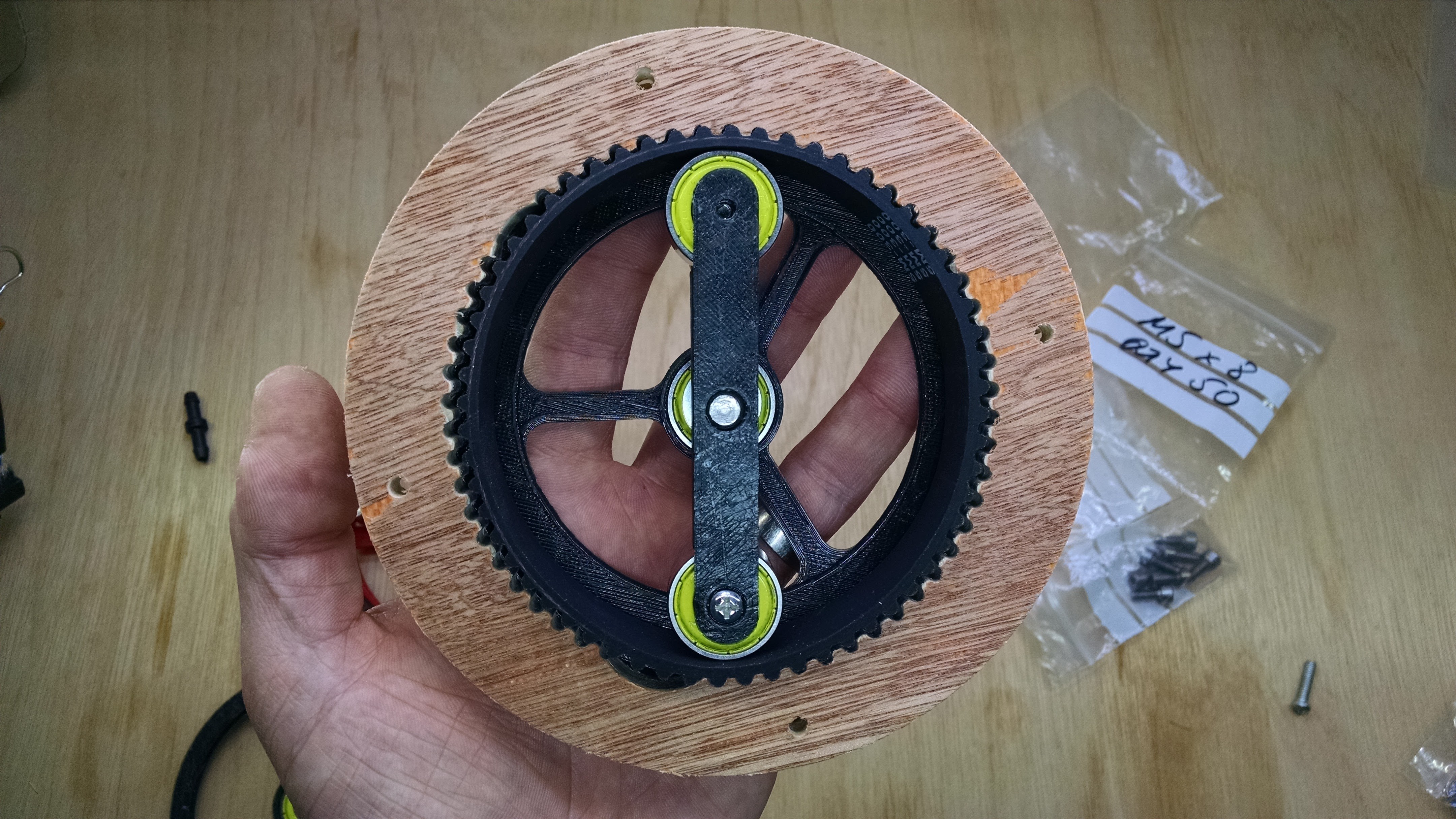
Please ignore the missing teeth - I was recycling previously-cut scrap plywood and I don't think the missing sections contributed to the play I report above, even though the photo shows the wave generator aligned with a missing portion of the gear.
Has anyone else tried printing/cutting any gears? I quite like the speed of the CNC as it took about 23 mins to make this ring, which is going to be much more suitable for a "rigid" version of this gear than the 3D printed one I started with (and about twice as fast). There's room for both techniques but strength is definitely going to be helped by a larger outer diameter on the mount gear and an additive process is going to lag behind a wasting process when making larger parts from sheet stock, in this scenario.
[edit 22:31 27/3/17]
In response to Florian's comments, I thought I'd add a couple of screenshots comparing the CAD from the parametric generator and my first revision design.
In the parametric generator, the diameter around the inner points of the teeth is 100.47mm and in mine it's 100mm. The gap for the belt teeth is narrower in mine (grey) than in the parametric generator (purple).
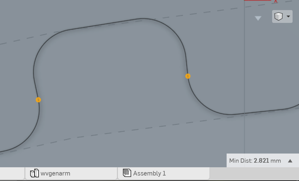
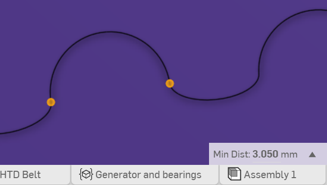
Anyway, the beauty of a parametric generator is that you can easily change all of this!
Discussions
Become a Hackaday.io Member
Create an account to leave a comment. Already have an account? Log In.
It would be interesting to figure out where the play comes from. Is it from the belt itself or is it slippage in the non 100% properly sized teeth of the second gear. May be the diameter of the ring gears need to be a bit bigger to make sure the belt is properly stretched. May be the wave generator needs to be an whole ellipse that keeps the belt stretched.
Are you sure? yes | no
Hi Florian, I've updated the log in response to your welcome comments as images can't be included in comments. I think the key is tightening up the "ring gears", whether that's reducing the pitch circle diameter or reducing the width of the gaps for the belt teeth to fit into.
Keep going with the laminated gears - locating pin holes sounds like a good plan.
Are you sure? yes | no
I am currently on vacation so I can only do software stuff for the next two weeks before I get back to my (hack space's) laser cutter.
Are you sure? yes | no
If you want another generator to look at you can try mine:
http://festi.info/boxes.py/Pulley
Set h to something sane (like 10mm), tick the insideout box and set axle to die outer diameter of the ring. But I just hacked in the insideout option recently, so it does not have any authority wrt doing the best fit. I basically just flipped over the teeth.
Are you sure? yes | no
Those two pictures are disturbingly different. I think they both don't match the shape of the belt very well. Not sure if this is enough to explain 2mm slack but I'd consider looking at other generators or adjusting yours. I stole the code and data from http://www.thingiverse.com/thing:16627 with looks much better IMHO.
Edit: The picture of the actual gear shows visible gaps even for the teeth directly above the bearing roller of the strain wave generator. No wonder there is slack.
Are you sure? yes | no
"I think they both don't match the shape of the belt very well." I can tell you mine is just notches with fillets! It was only intended to make the proof of concept prints. In fact my printer isn't so accurate that it would have accurately produced that profile either.
Yes, there is play in the CNC'd notches for the belt teeth but I can't purely blame the generator. Only just got the CNC up and running. As I said, don't need to worry too much as long as we err on the side of narrower notches for the belt teeth. That's the beauty of a parametric generator.
Thanks for the link to your generator (and I've used that Thingiverse / OpenSCAD generator before). I couldn't get the save as svg to work. I can see the profile is different but I think the key is to have two points of contact on the sides of the belt tooth before the tooth reaches the back of the notch. If you achieve that, you eliminate rotational backlash, but admittedly may not maximise load transfer.
Are you sure? yes | no
I have some limited experience with cutting out gears and pulleys with a CO2 laser cutter with is about another factor 10 or 20 faster than the CNC. The gears seem so run nicely. Although I do not have too much experience with them yet. Unfortunately the laser likes thin material. So wider gears need to be glued together from layers. This is surprisingly difficult. I still need to add holes for alignment pins to my gear generator.
If the play issue with this setup cannot be solved we may be a planetary gear with differential ring gears is an alternative.
Are you sure? yes | no