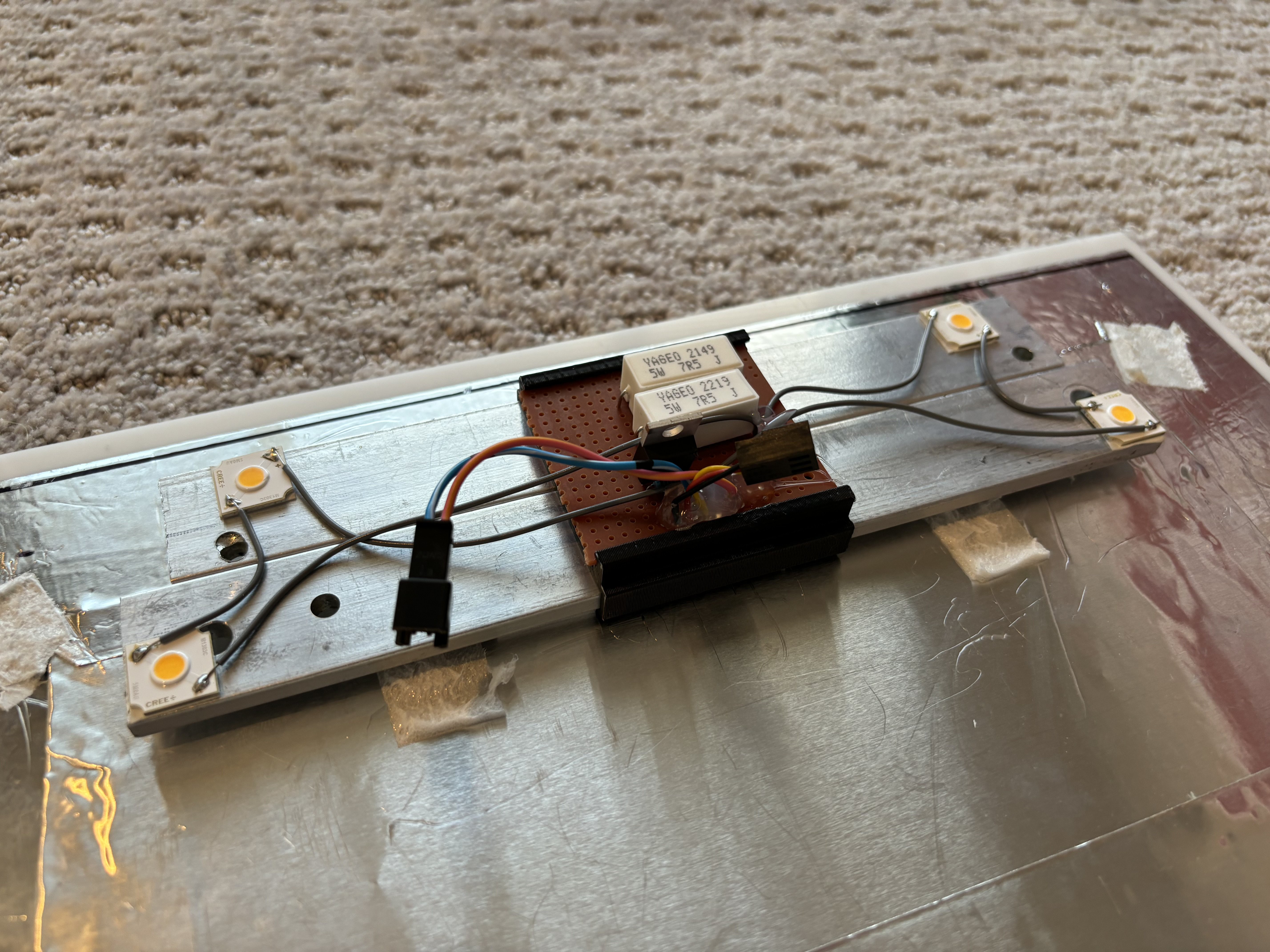
The current LED lighting setup is the 4th revision of what started as a $30 light ring from Amazon. Here’s the specs of what I’m using now:
- 4 high-CRI, super bright, reasonably priced ($3) Cree LEDs
- Brightness controlled through PWM by a GPIO output from the Pi
- Super simple driver circuit - a MOSFET for switching and 2 power resistors for current limiting
- 28W max power (though the heatsink probably isn’t big enough to sustain this for long)
- Powered by a cheap 24V 36W DC supply
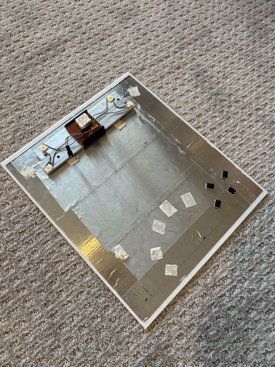
An important constraint to note is that the heatsink probably isn’t big enough to let the LEDs run at a high PWM duty cycle for more than a few seconds. This is acceptable for this application because the LEDs only have to be super bright for long enough to capture the photo. The rest of the time, they’re kept on at about 20% duty cycle to give the photo booth an inviting glow.
Here’s the schematic of the driver circuit. As you can see, it’s quite simple, but so far it’s done the job.
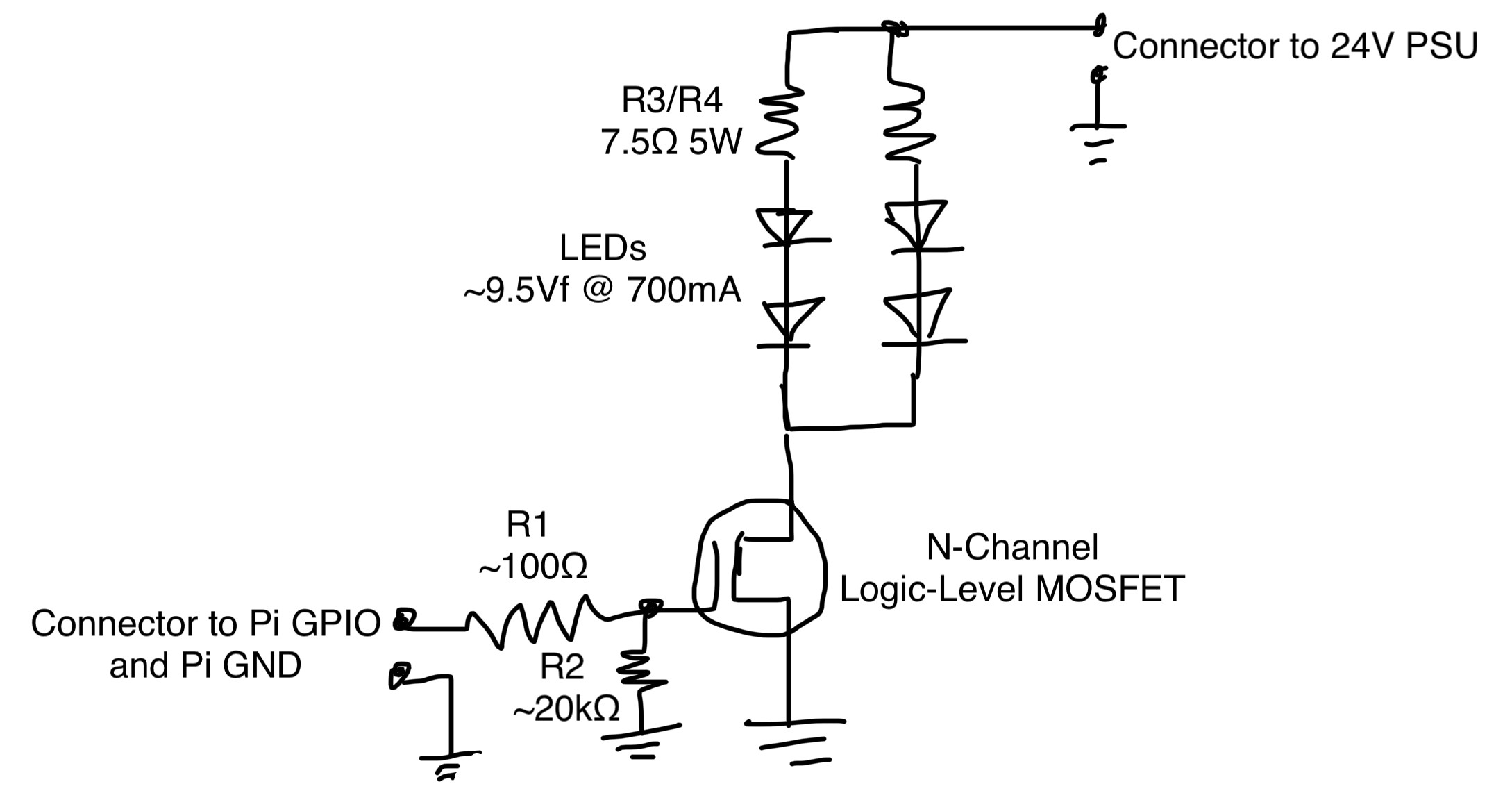
R2 is very important, it pulls the MOSFET gate low when the Pi GPIO pin is not driven so the LEDs don’t stay on and burn out. The Pi GPIOs float when it’s booting up, and this takes long enough that the LEDs could burn out if they were fully switched on during this time. R3 and R4 set the current to the LEDs to about 700mA. The LED strings are switched by a N-Channel MOSFET with a low gate threshold voltage. I chose the DMT6009LCT but I’m sure there are plenty of other options that would work as well.
Discussions
Become a Hackaday.io Member
Create an account to leave a comment. Already have an account? Log In.