 Alan
AlanOverview
It is not long before Raspberry PI 5 is commercialized.
So, let's do a project to connect Raspberry PI 5 and WIZnet.
Following the development of 8W-class PoE, this time, we will make 30W-class PoE products that meet IEEE 802.3at.
However, since Raspberry Pi 5 has not been released yet, we will proceed with Raspberry Pi 4.
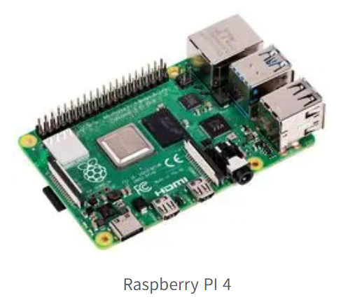
It looks like this. And Raspberry PI 4 has an issue that generates a lot of heat. (Of course, if you use a lot of current)
So most of them use coolers in their cases to use them properly.
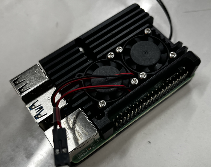
Our company also reviewed Raspberry PI 4, which was equipped with a case like this, because it rolled around.
No matter what Cooler case is installed, I won't block the I/O header, so I thought I should make a module that can only be used by I/O headers.
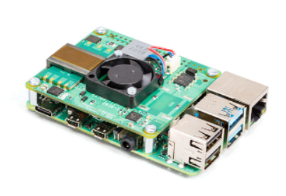
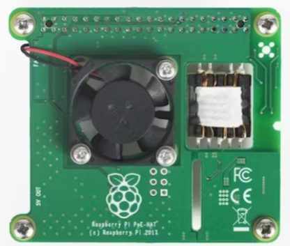
In fact, PoE and PoE+ HATs are released on the market like this. But what I want to do is to get power from the WIZnet Chip and make a module that can be used as Raspberry PI 4's existing Ethernet and Two Port.
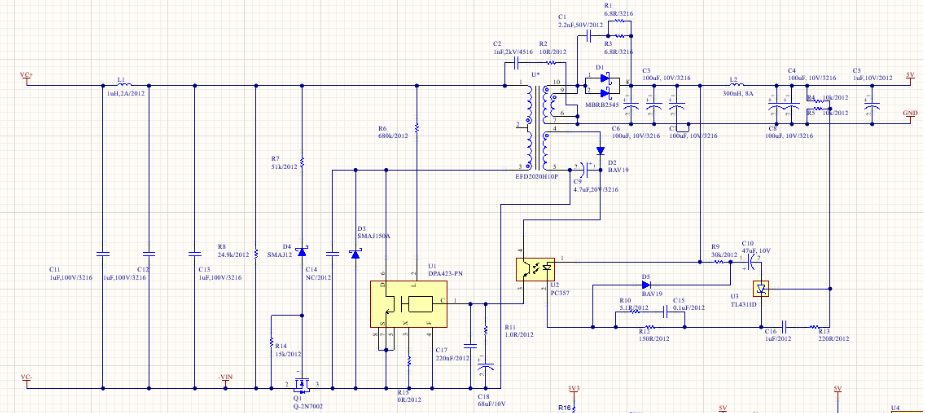
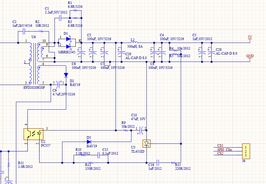
The circuit is organized like this. First of all, it's not cost-effective. It's PoE+ that I'm making for the first time, so if it works well, I'll gradually change the device. First of all, I thought it would be strong and work well, so I boldly used good devices.
Device selection
IC
The method is the Flyback method, and the IC will use Power Intersection's DPA series...
It's expensive, but I like it because it has a lot of protection. (Disadvantage: I have to decorate the detecting circuit separately.)
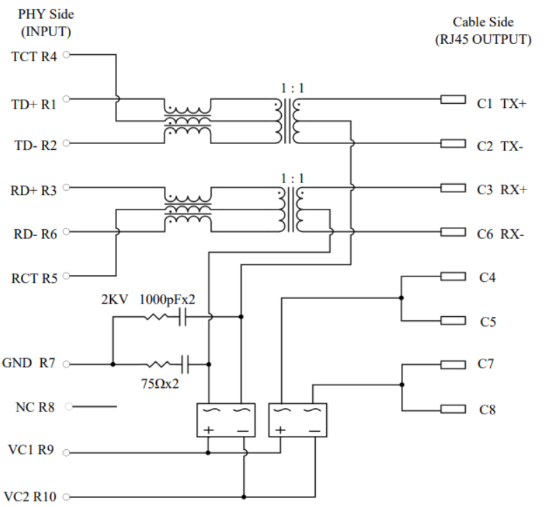
RJ-45
I'm choosing between UDE and TRX products. The ones I've decided are Pin to Pin, so I think I'll try both and choose the one with better characteristics. Internal circuits are not very different. Oh, but the advantage of UDE's RJ-45 is that it has a rectifying circuit inside. (However, I think the characteristics will deteriorate.)
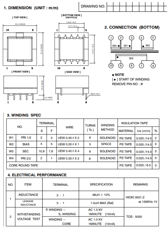
Trans
I was able to customize it through a company I knew at the exhibition. Thank you for sending the sample in a friendly way for free.
The size was larger than expected. The winding ratio is primary side: secondary side: Aux=1:0.5. The inductance is 49uH and the leakage inductance is 1.0.
** As a side note, the company that makes Trans didn't like Power Intervention. EMI RE is coming out too big. I also heard that the internal oscillation was severe, but I thought it would be difficult to catch it easily because the switching frequency exceeded 300k and 400k. As the frequency is high, you can take a small C at the back, so it's perfect for my project that needs to be compact.
Design
Circuit design
It was simple. In fact, there was nothing difficult other than device selection, so I was able to proceed quickly. When it's difficult, it starts when you assemble and then switch devices to debug.
Artwork
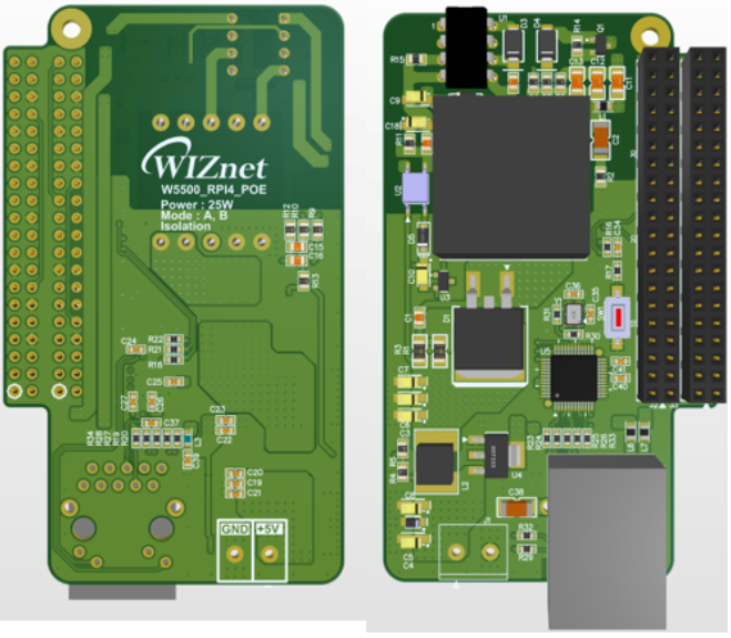
I made it clean quickly.
The left side is the front side and the right side is the back side. The devices are so big that they are made too big...
But since it's a test board, order it right away
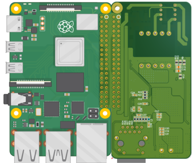
Maybe this is what it looks like when you mount it on Raspberry PI 4.
PCB assembly
Once the PCB arrived, I assembled the header and RJ-45 as soon as it arrived. It needs to be fit on the machine, so check first
It's a good fit. But I think everyone in the audience will feel the same way... It's too big.
The connector also fits very neatly. I hope it works well.
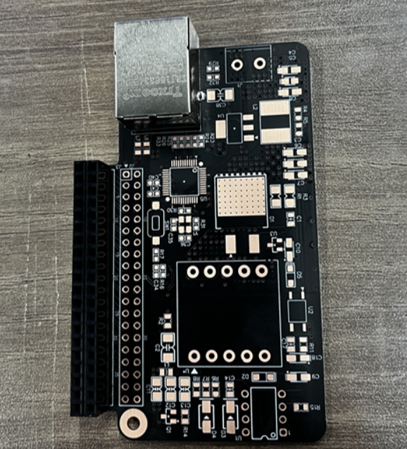
The assembly was carried out.
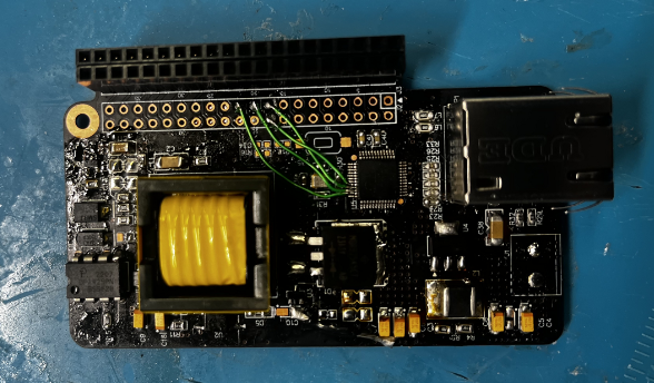
Assembly done. Debugged and I had a little problem, so I flew my jumper...
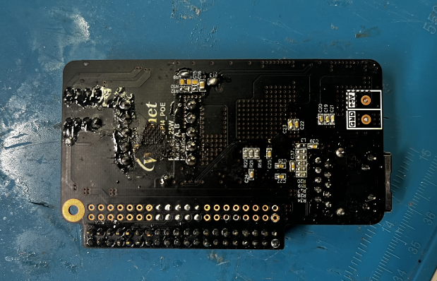
This is the back. The WIZnet logo was smashed. The Tranfomer designer made the wrong Trans, so I ran it, and it exploded right away. (I was really surprised that it burst with a bang...) They quickly made a normal sample again, so I was able to proceed with the test.
We started debugging with Power Supply to test the PoE Detection circuit with good voltage before operating it.
In this process, the oscilloscope was not insulated, so the rectified diode inside the Transformer continued to explode..
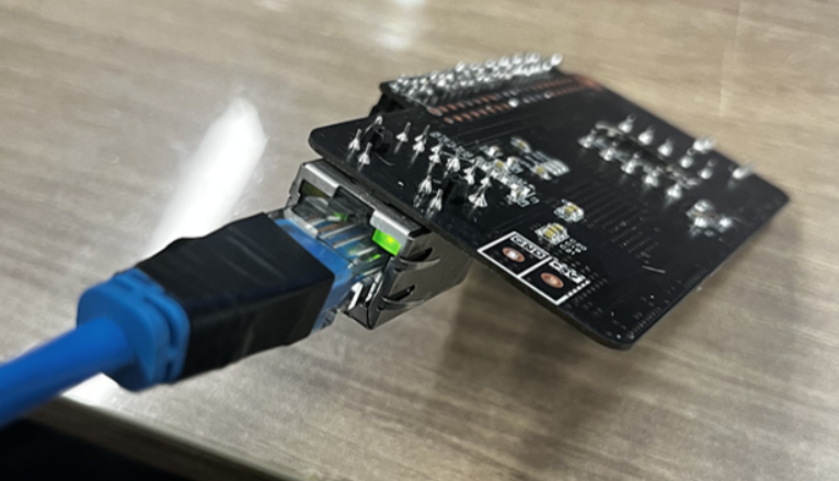
The waveform was not good, but after confirming that it operates normally up to 25W with Power Supply, I installed it on the PSE to verify the detecting circuit, and it operated normally. It was confirmed that the Link LED and Act LED came in normally.
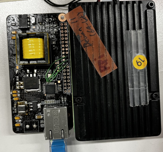
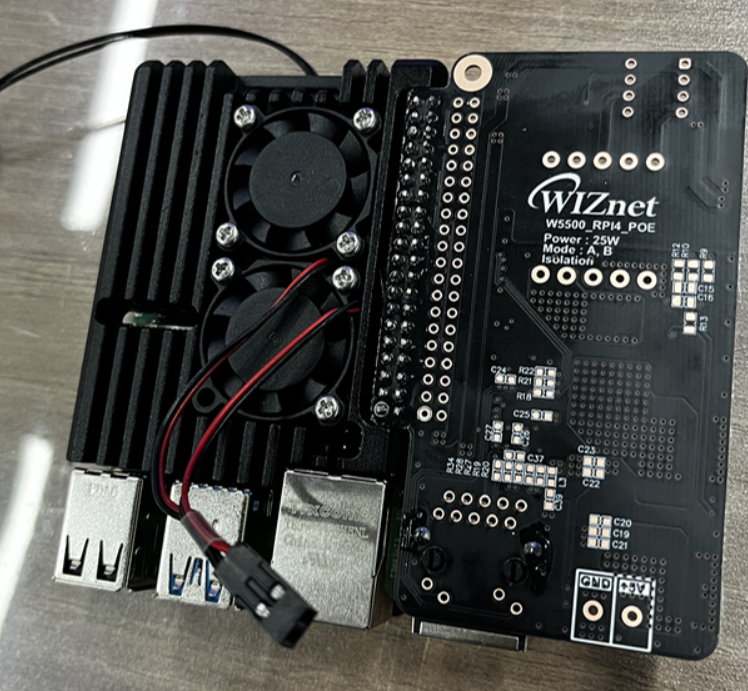
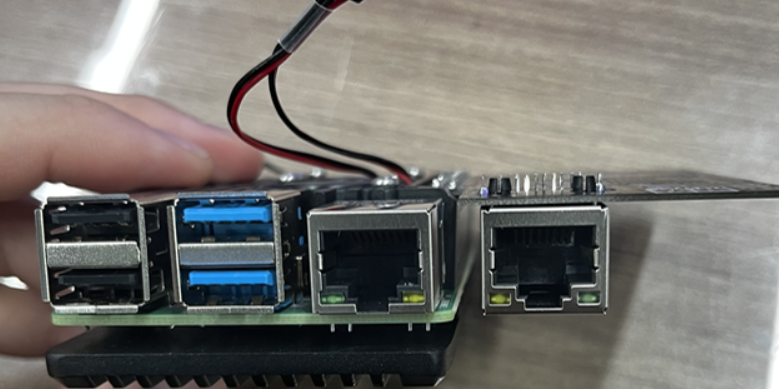
And I put it on Raspberry Pi 4. It doesn't look very pretty..
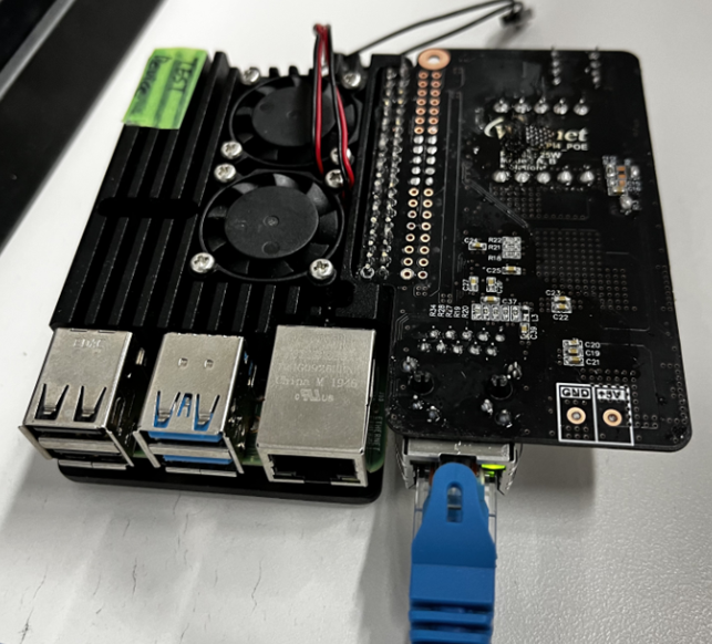
The Ethernet Conector was positioned neatly, but the PCB was so big that the side projection was a little bad.
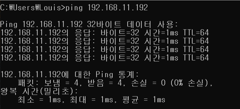
Still, it has even confirmed that Ethernet communication operates as heavily as possible.
The Aging Test was conducted at 25 W full load.
Finally, Raspberry Pi 5
Finally, Raspberry Pi 5 has been released.
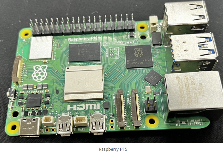
Now, we will proceed with the module with the PoE+ that was conducted on Raspberry Pi 4 as if it was upgraded from Raspberry Pi 5.
I felt the absence of the output stage capacitor so desperately that I designed two additional large electrolytic caps. We will find the appropriate value by changing the value directly. And the snubber circuit resistance and the size of the capacitor were slightly increased.
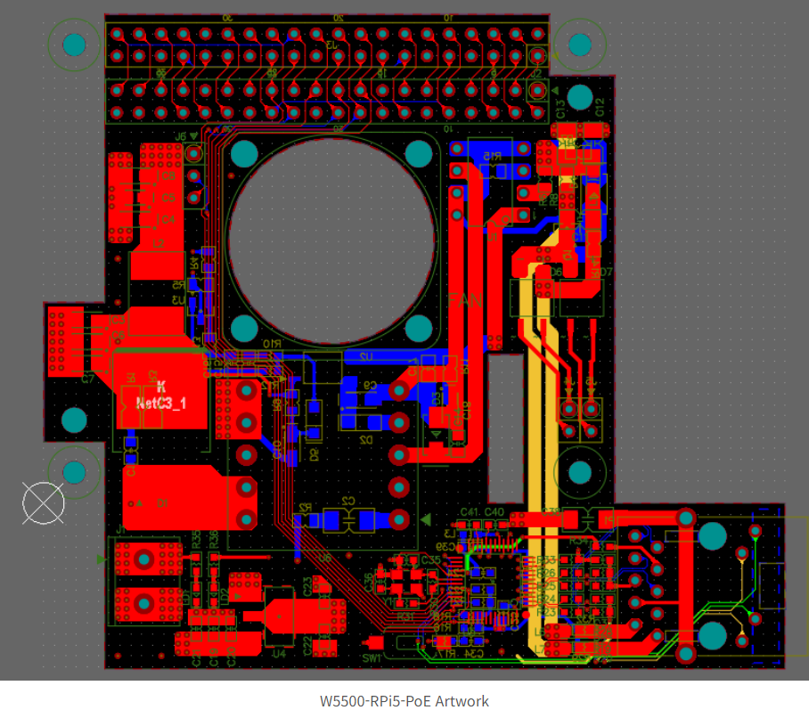
It looks like he's done with Artwork. (Except for Polygon)
I wanted to make the Cooling Fan as big as possible, but I compromised and compromised and finally decided on 30x30...
And MIPI Connector has also been created so that it can be used.
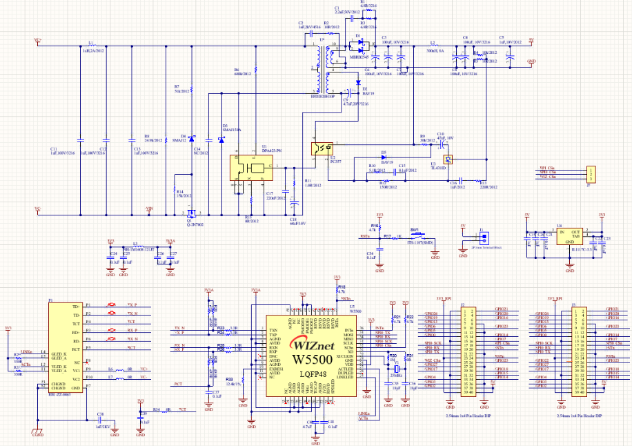
This board is designed to use Ethernet using the WIZnet Chip. Of course, the existing Ethernet can also be used. In addition, it was designed to be used up to PoE+, which can be used not only through the WIZnet connector but also through the existing Ethernet connector.
The key will be how well cooling performs and how well it performs.
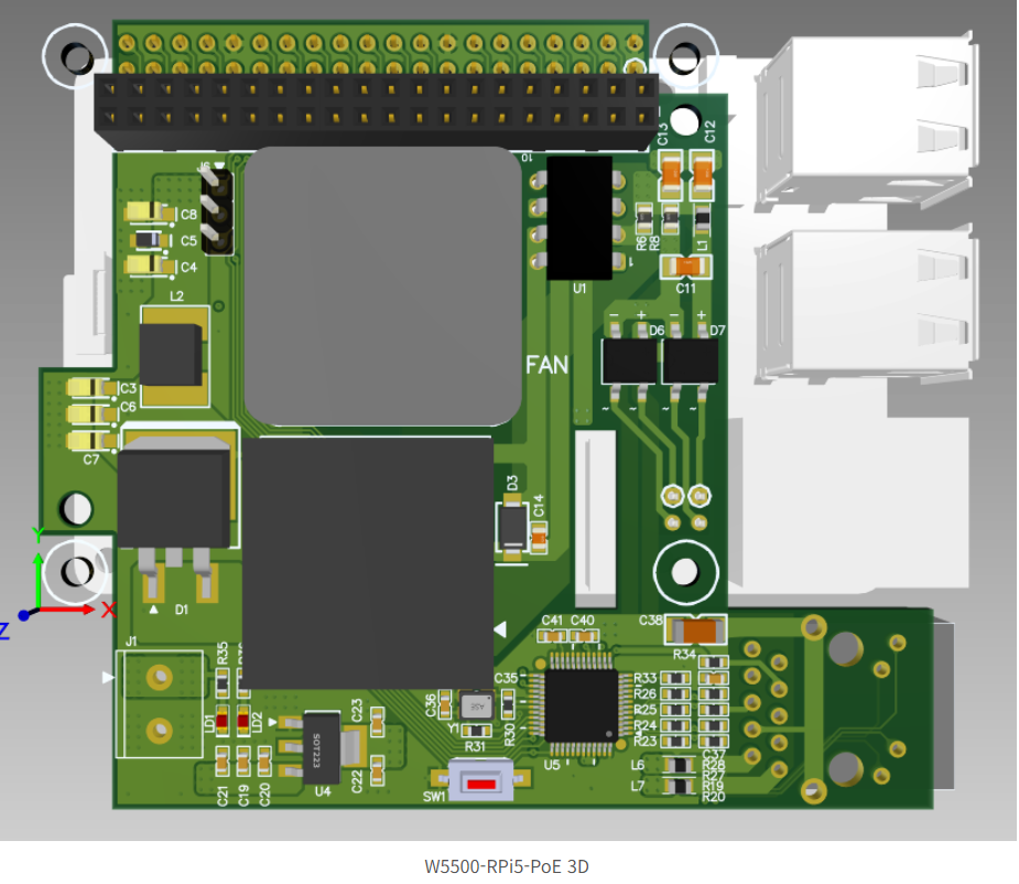
I tried the Raspberry Pi 5 Step File provided by RPi in 3D with my board. It looks like this because there are many things that don't have a 3D library, but I don't think it's bad.
When the board arrives, I will continue with the next article.