 mircemk
An oscilloscope is a measuring instrument used to visualize and analyze electronic signals. It is commonly used in various fields, including electronics, telecommunications, engineering, and physics. Overall, oscilloscopes are essential tools for engineers, technicians, and scientists involved in electronics and signal analysis, enabling them to visualize, measure, and diagnose electrical waveforms accurately.
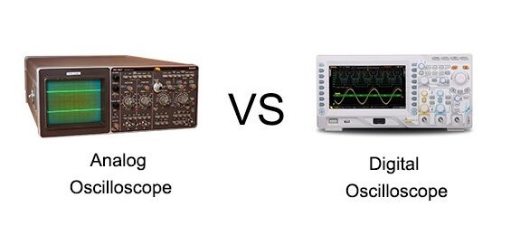
Nowadays, analog (CRT) oscilloscopes are no longer produced, but only digital ones, due to their huge advantages. One of the advantages of analog oscilloscopes is real-time, high-resolution imaging of the signal, and also easier to use than digital oscilloscopes.
In this video I will present to you the simplest possible way to make a retro-style analog oscilloscope with a cathode ray tube (CRT).
A cathode-ray tube (CRT) is a vacuum tube containing one or more electron guns, which emit electron beams that are manipulated to display images on a phosphorescent screen. A CRT tube can be obtained on the Internet for a relatively low price, and depending on the dimensions, it ranges from $20 and up.
And at the beginning, let me say that this is not a serious instrument, but only a demonstration model to describe the way these instruments work.
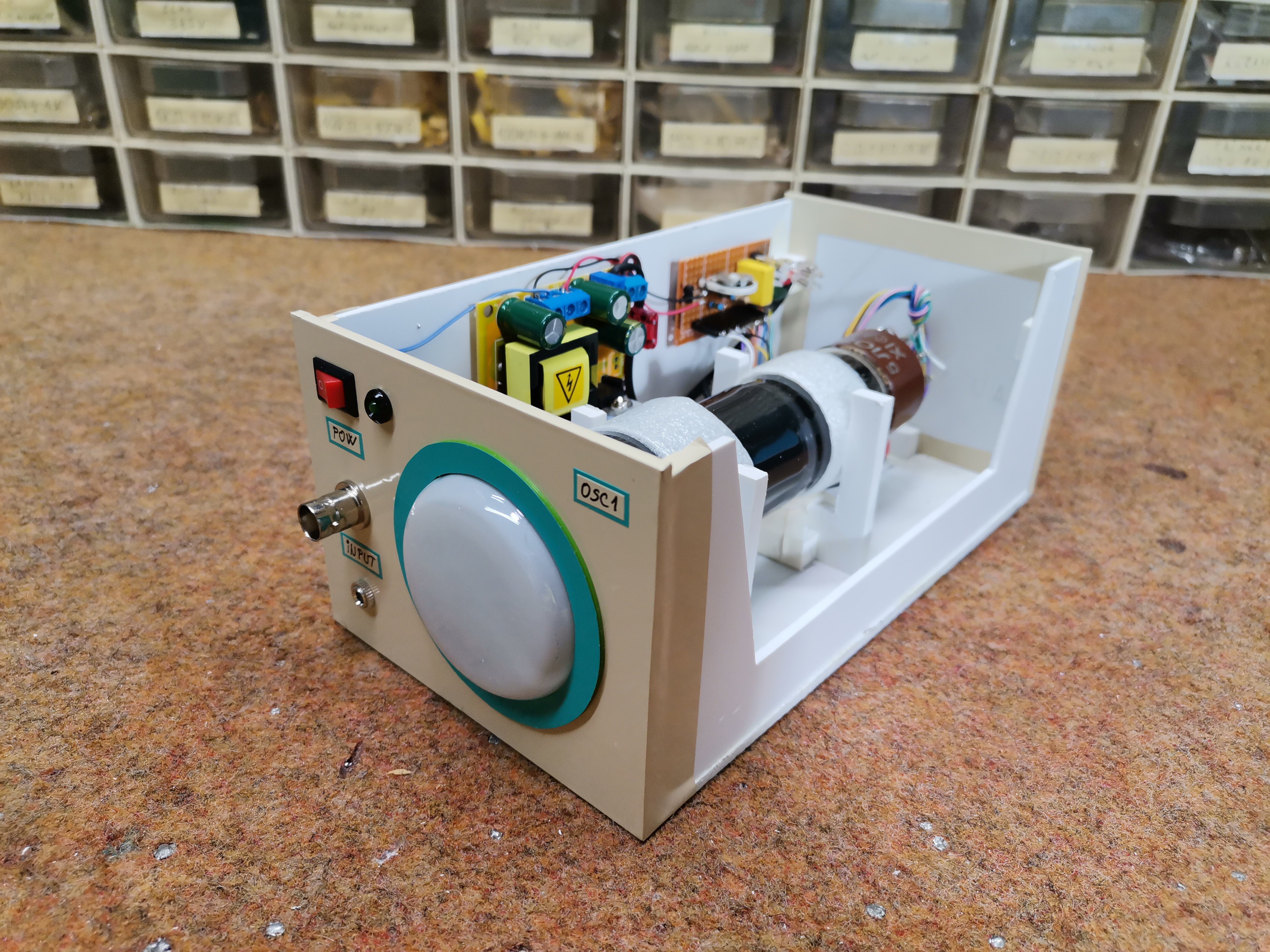
In previous years, this device has been described in several magazines and portals, but I could not find any pictures or a video presentation of its operation anywhere. So I decided to make it and present the results to you. As the title suggests, the device is extremely simple and consists of several components:
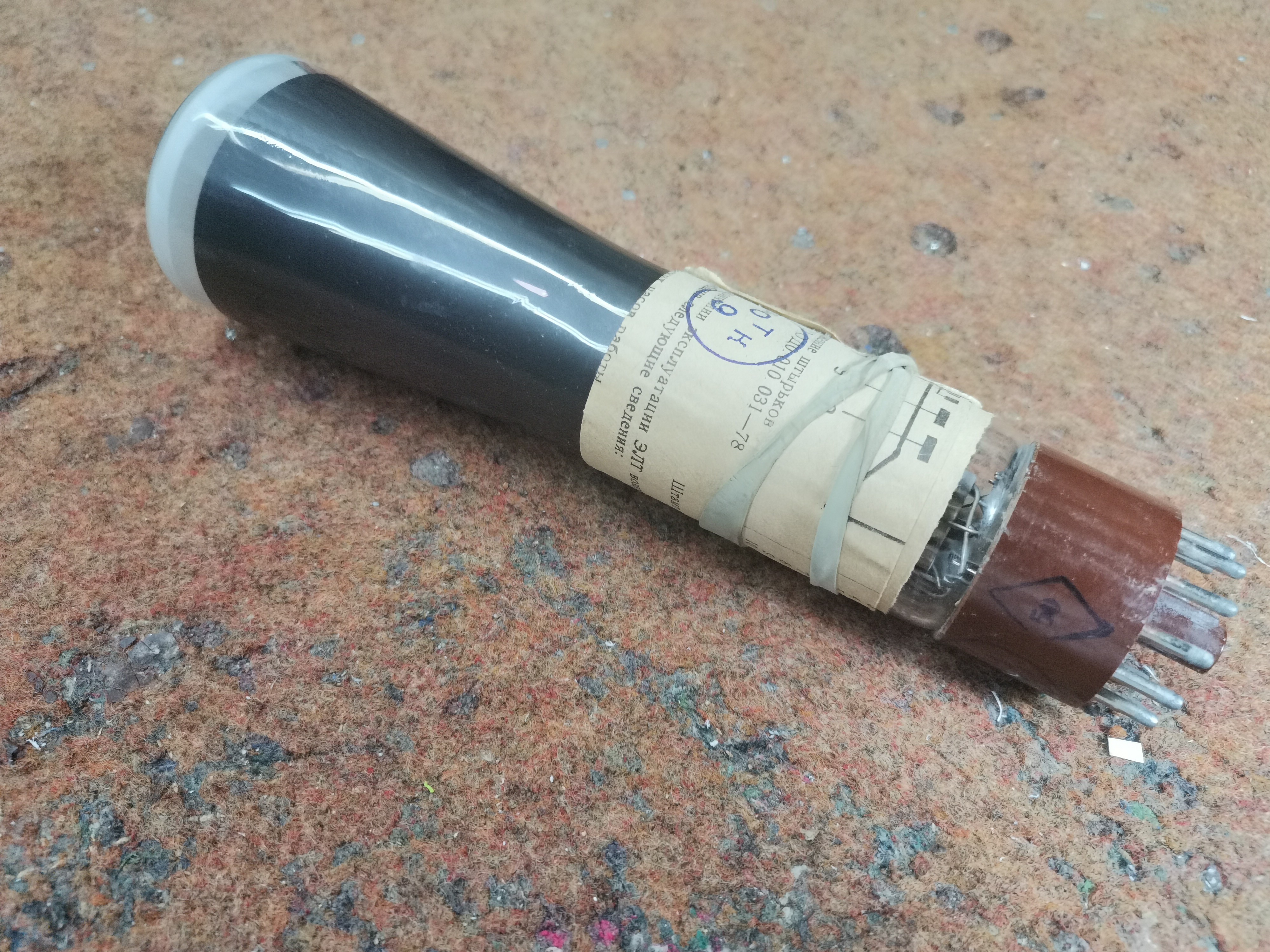
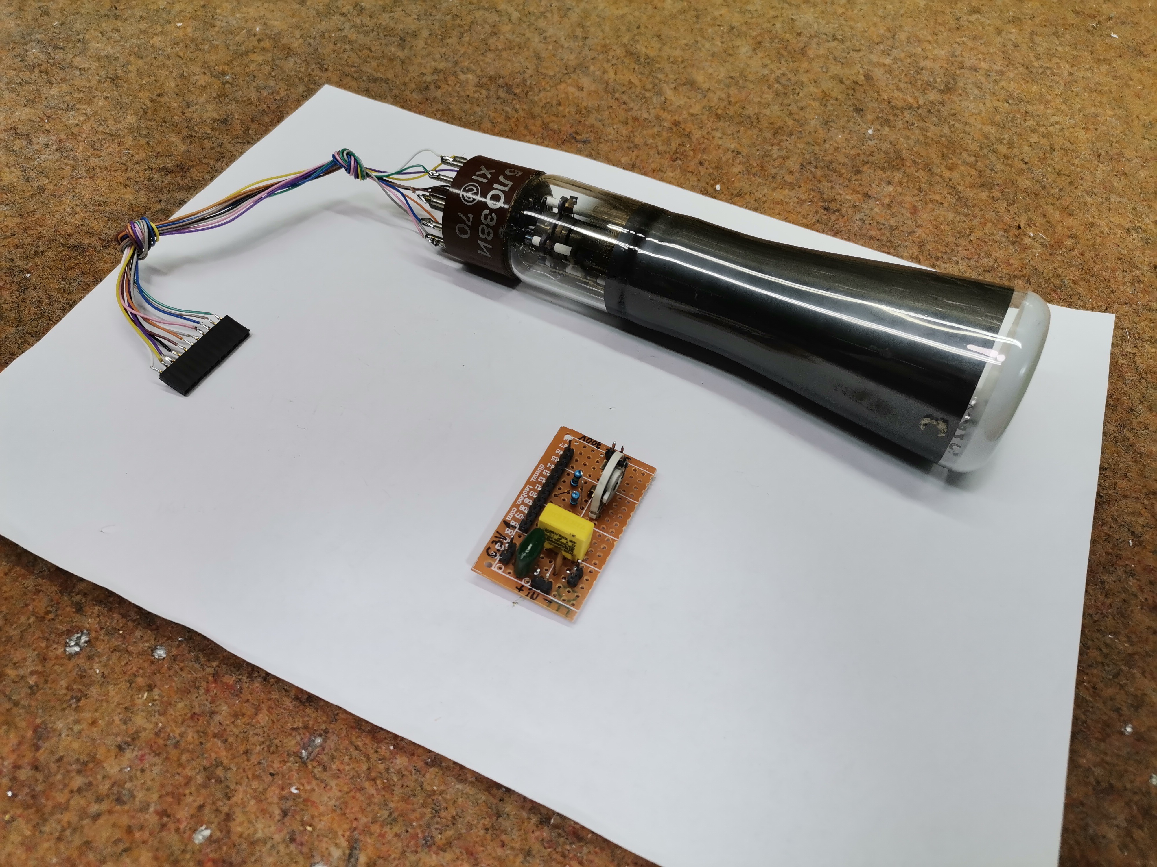
- The main part is the cathode ray tube, and in my case it is a miniature CRT marked 5LO38I with a diameter of only 5cm.
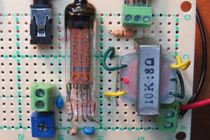
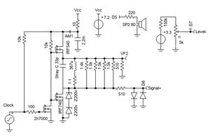
- An electronic part that is extremely simple, and consists only of a few resistors and capacitors.
- LM317 adjustable voltage regulator and two resistors to get the 6.3V needed for the tube heater.
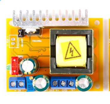
- and power supply - this part is the most common reason why we do not start making devices with electronic tubes. Namely, for their normal operation, high voltages are needed, usually more than 200V, and such power supplies with a classic transformer are bulky and expensive. Specifically for this purpose I used this small compact boost converter which costs only 3 dollars and with 12V at the input gives an output of 45 to 400 Volts, which can be changed continuously with a small potentiometer. The power is quite sufficient for any CRT tube..
And now let's explane how this small oscilloscope works.
The input signal is fed to the Y input via a suitable capacitor to one of the Y deflection plates. For X deflection we use a neon lamp oscillator to generate a timebase, and with a focus regulator circuit we have a complete oscilloscope. Operation of the horizontal deflection oscillator is visible as the gentle flickering of the neon lamp. Whenever the voltage across the parallel-connected capacitor reaches the strike voltage of the lamp, it is discharged with a brief pulse of current. It is hard to imagine a simpler way to generate a sawtooth waveform.
Now, if a signal is applied to the Y input, we should be able to see the waveform on the screen. So, I have shown how little circuitry is required to make a real working oscilloscope.
Let me mention that this device is double isolated from the city voltage network. Once in the external power supply, and the second time in the boost converter.
At first start, it takes a certain amount of time for the cathode to start emitting electrons and an image appears on the screen. Now we will feed the sinusoidal signal generated by this tone generator to the input.
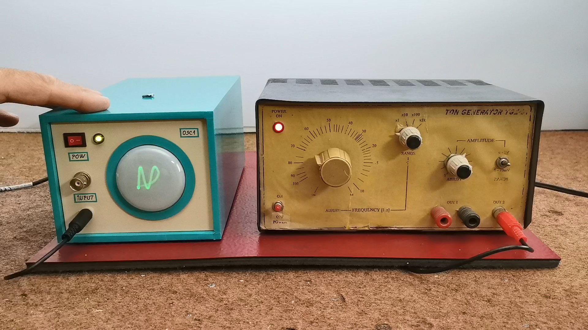
The shape of this signal appears on the screen. We can see that we get a stable image only at certain frequency values because, for the sake of simplicity, the device does not contain a trigger circuit. ( We can also look at the shape of the square wave generated by this small...
Read more »
 kodera2t
 agp.cooper
Awesome, just wondering if the same circuit could be applied to similar NOS CRT tubes, such as 8ЛО6И (8L06I)?