 Keith
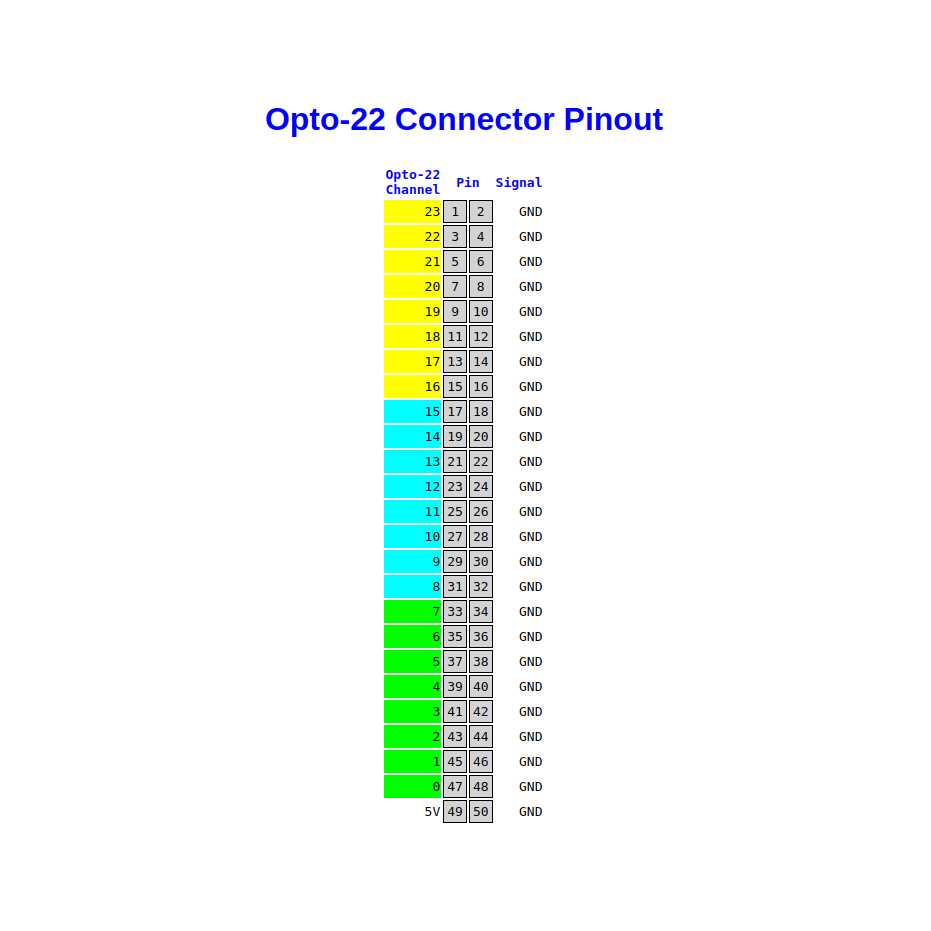
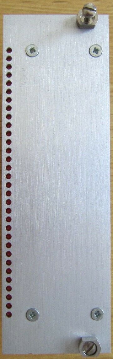
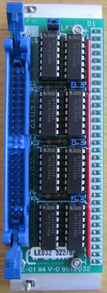
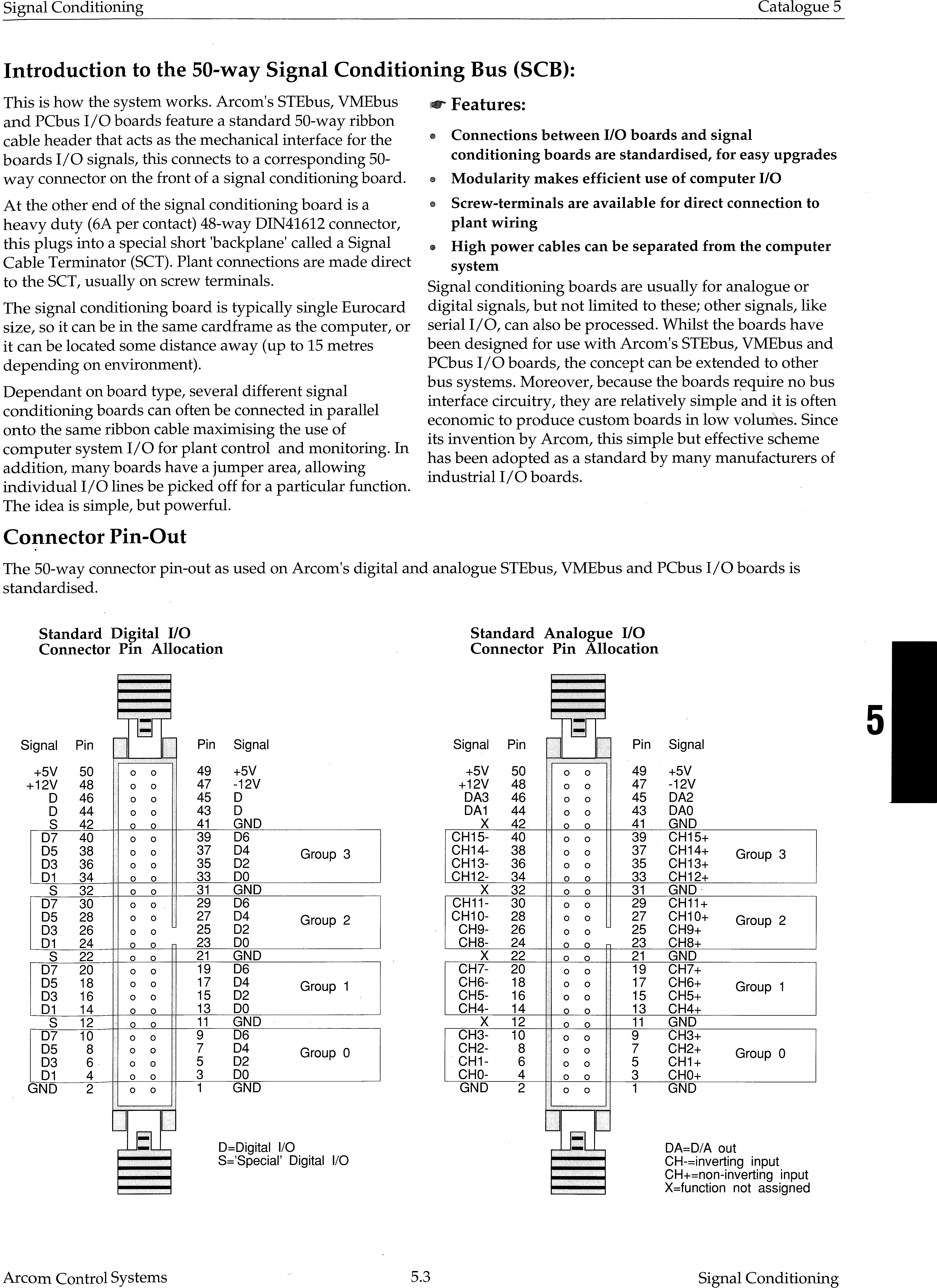
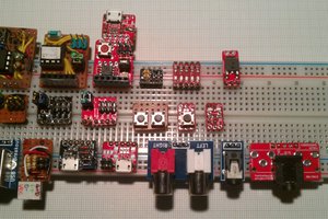
KeithBasically all I need to do is put two I2C/SPI-to-parallel-I/O chips onto a board and wire them to a 50-way connector, then add some 5V and 12V power rails.
It can then be used as an I2C/SPI peripheral straight away.
The UMFT4222EV is a USB to I2C module which allows a PC with a USB port to access the I2C bus.
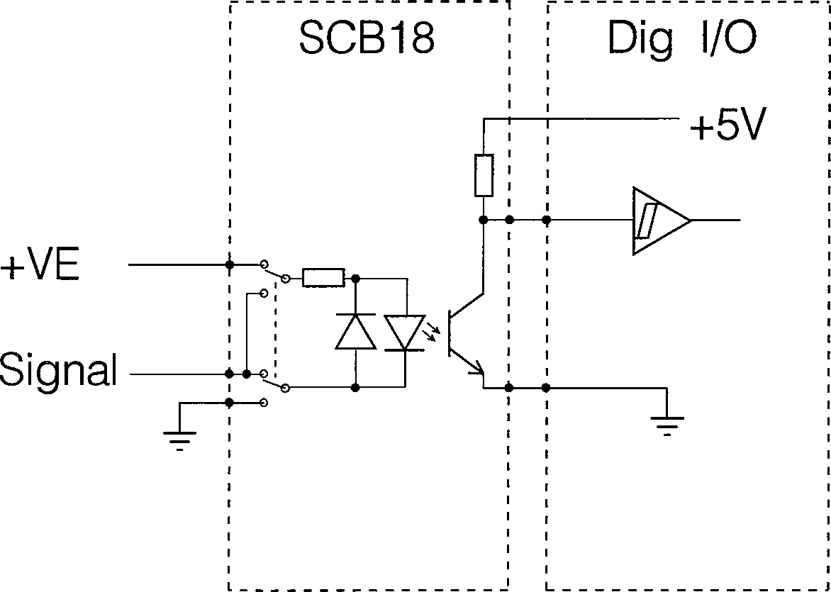
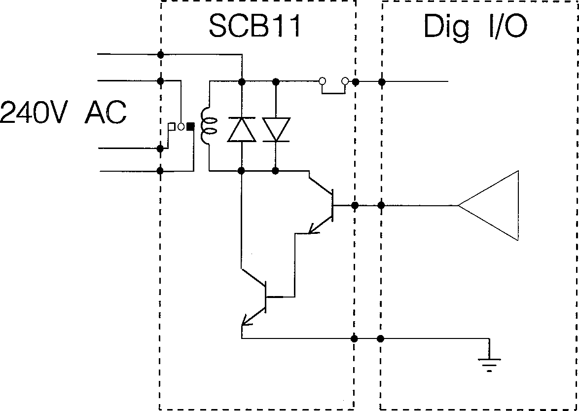
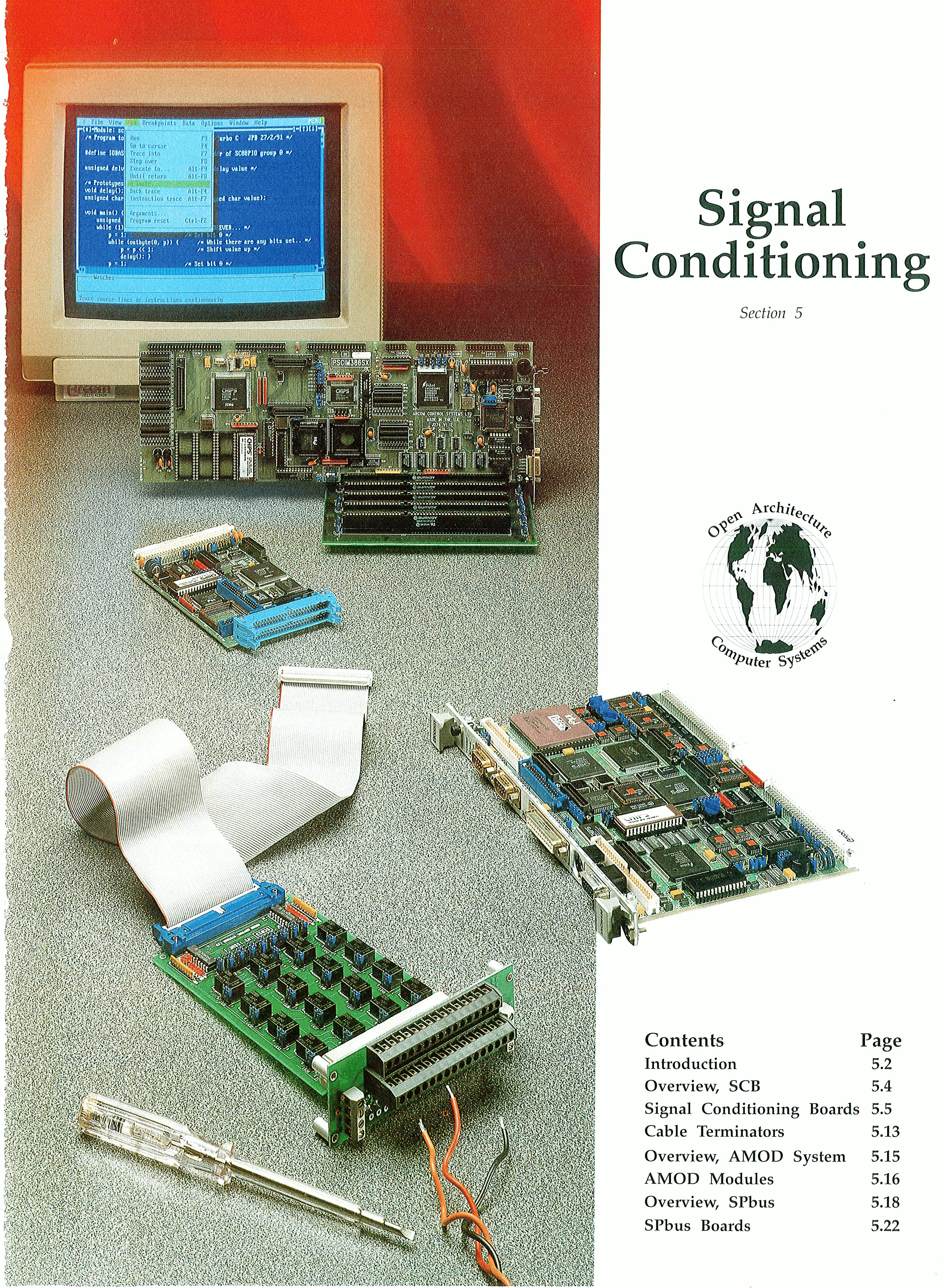
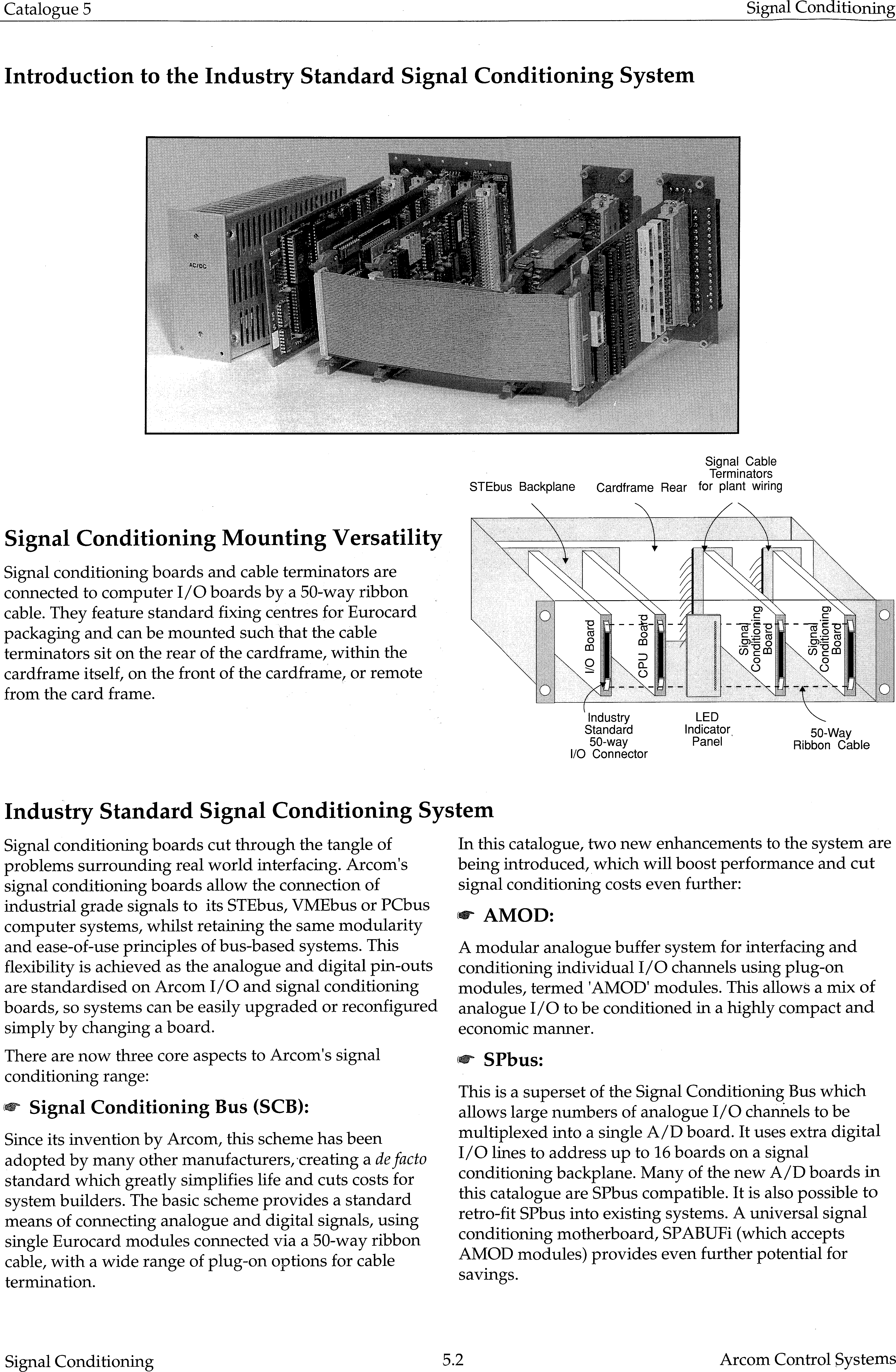
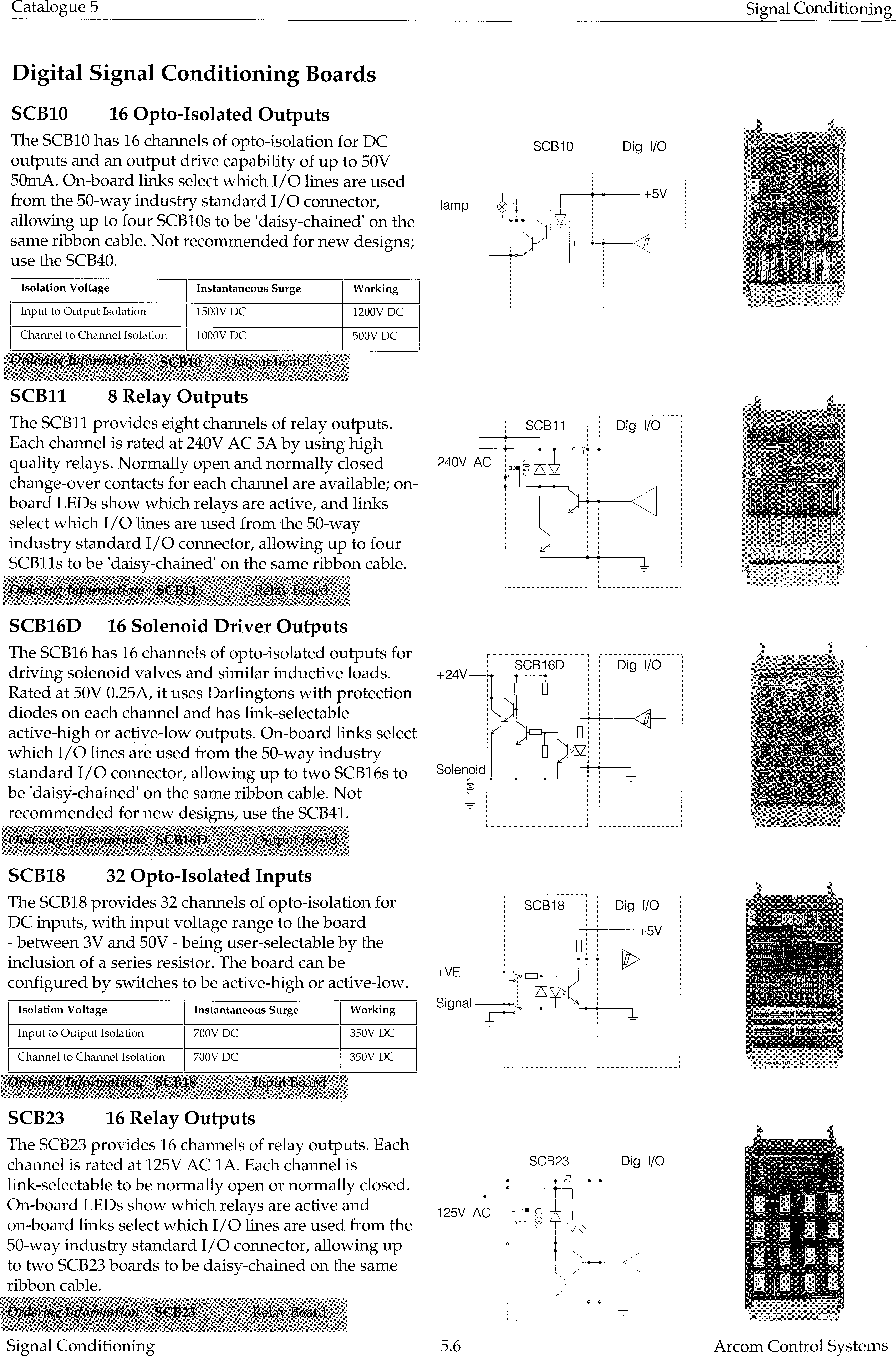
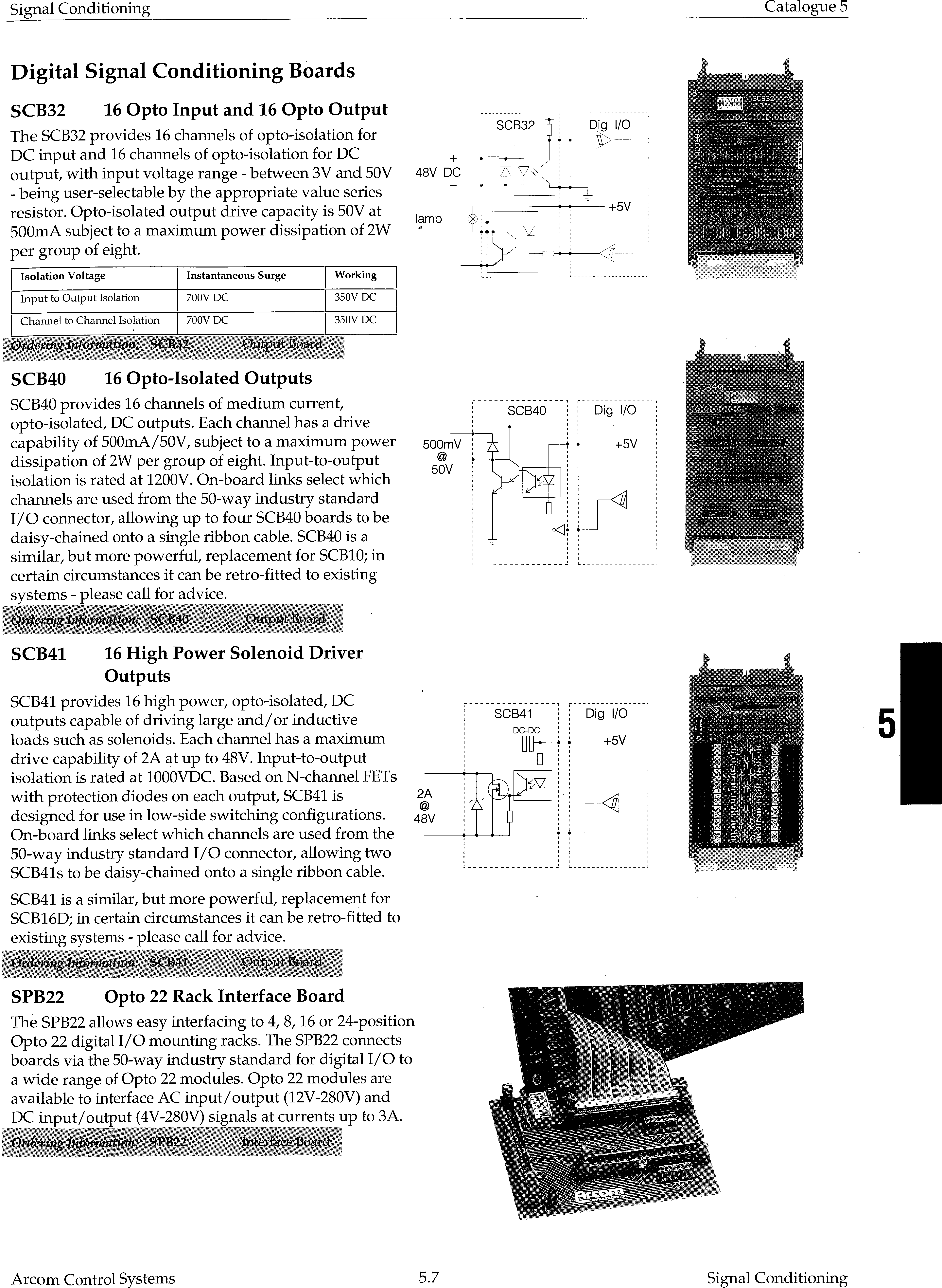
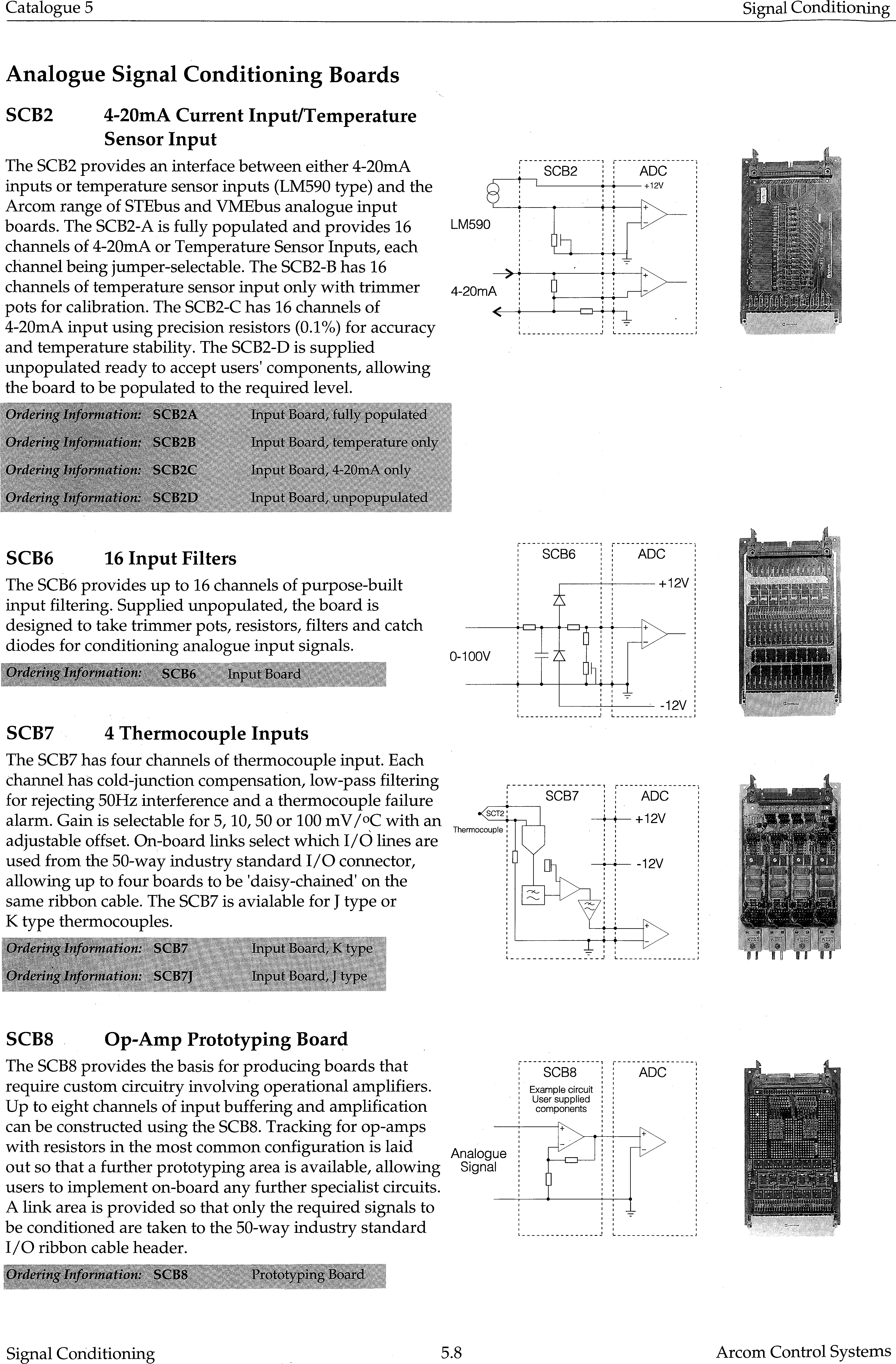
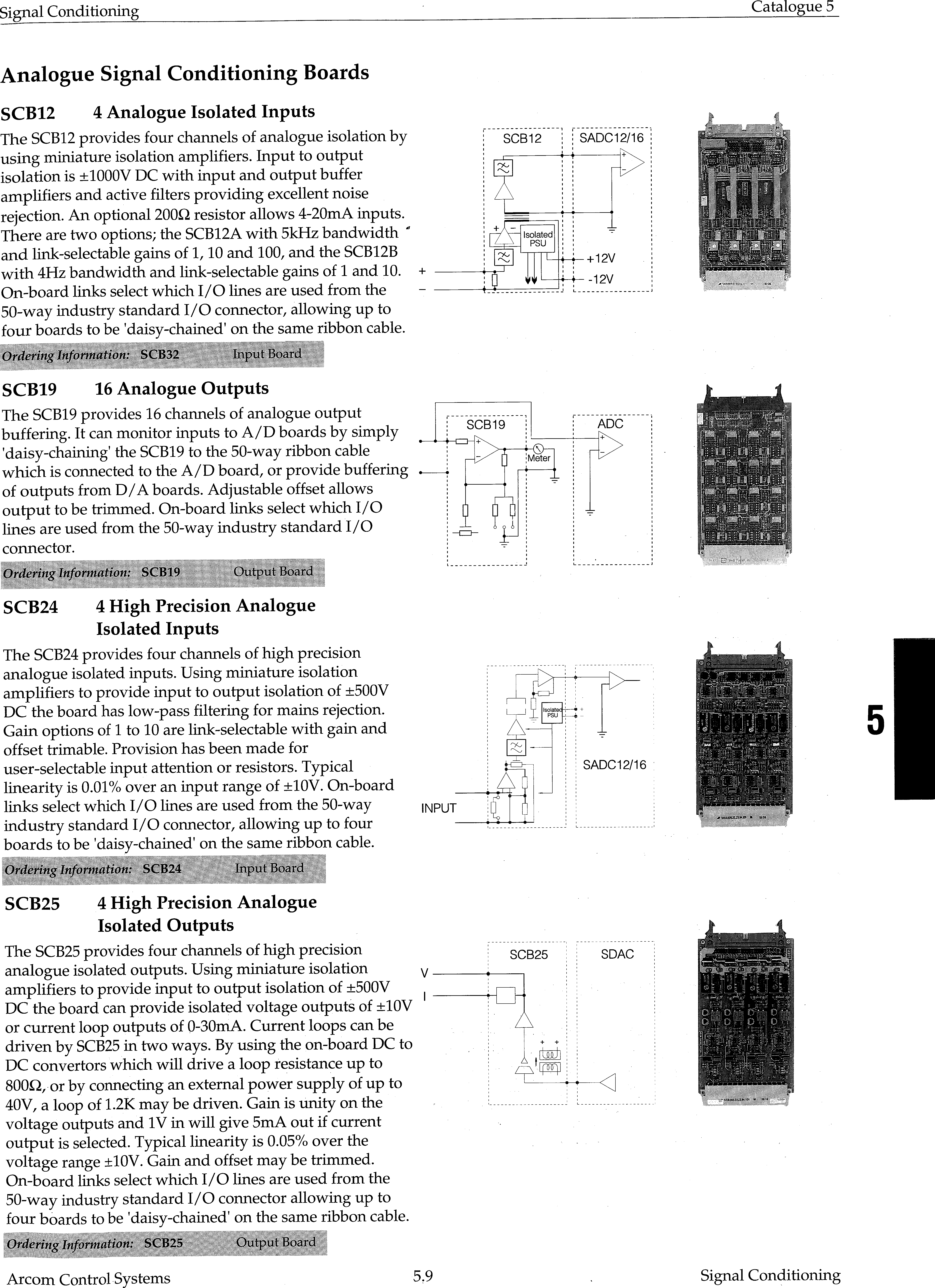
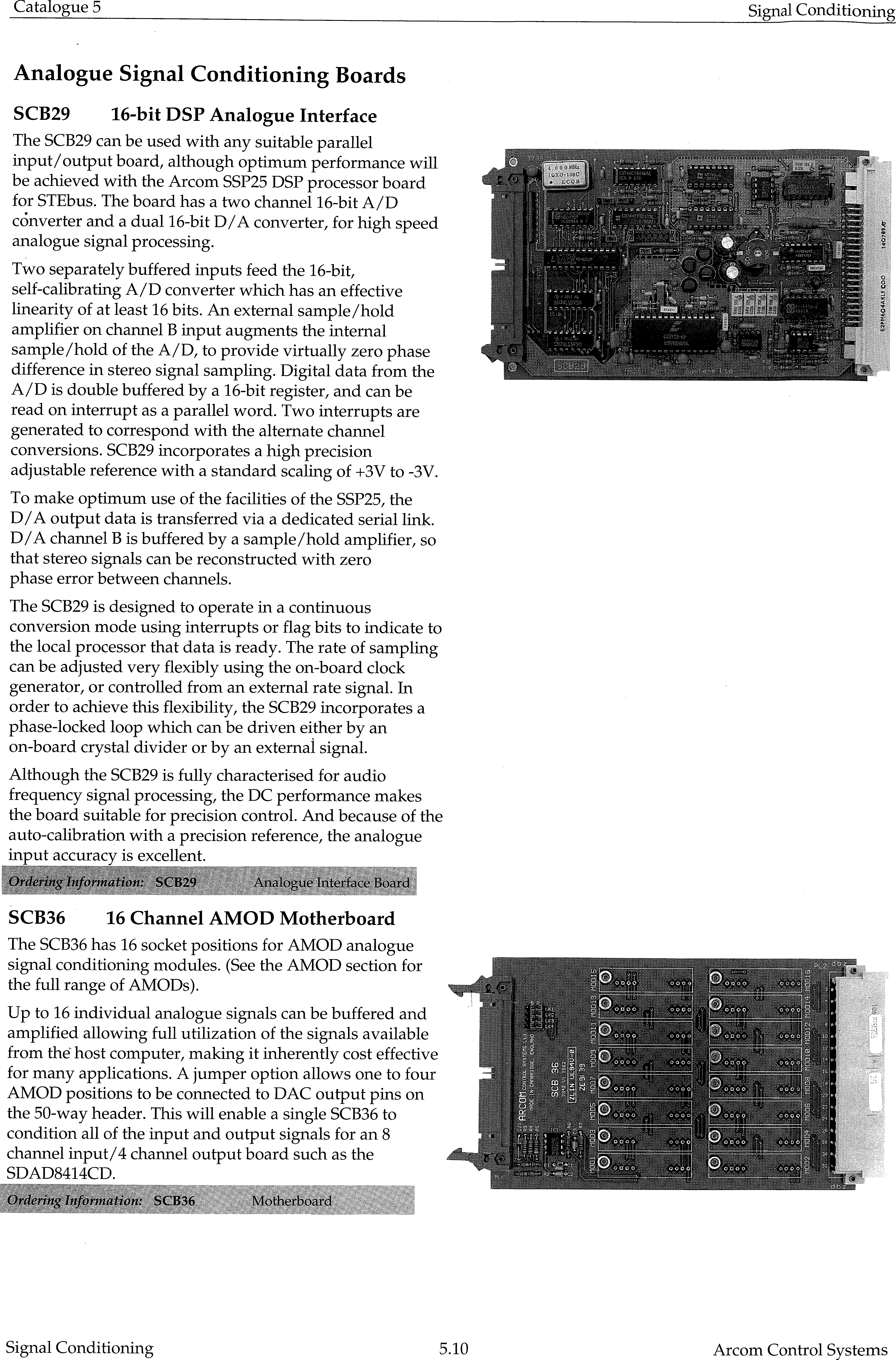
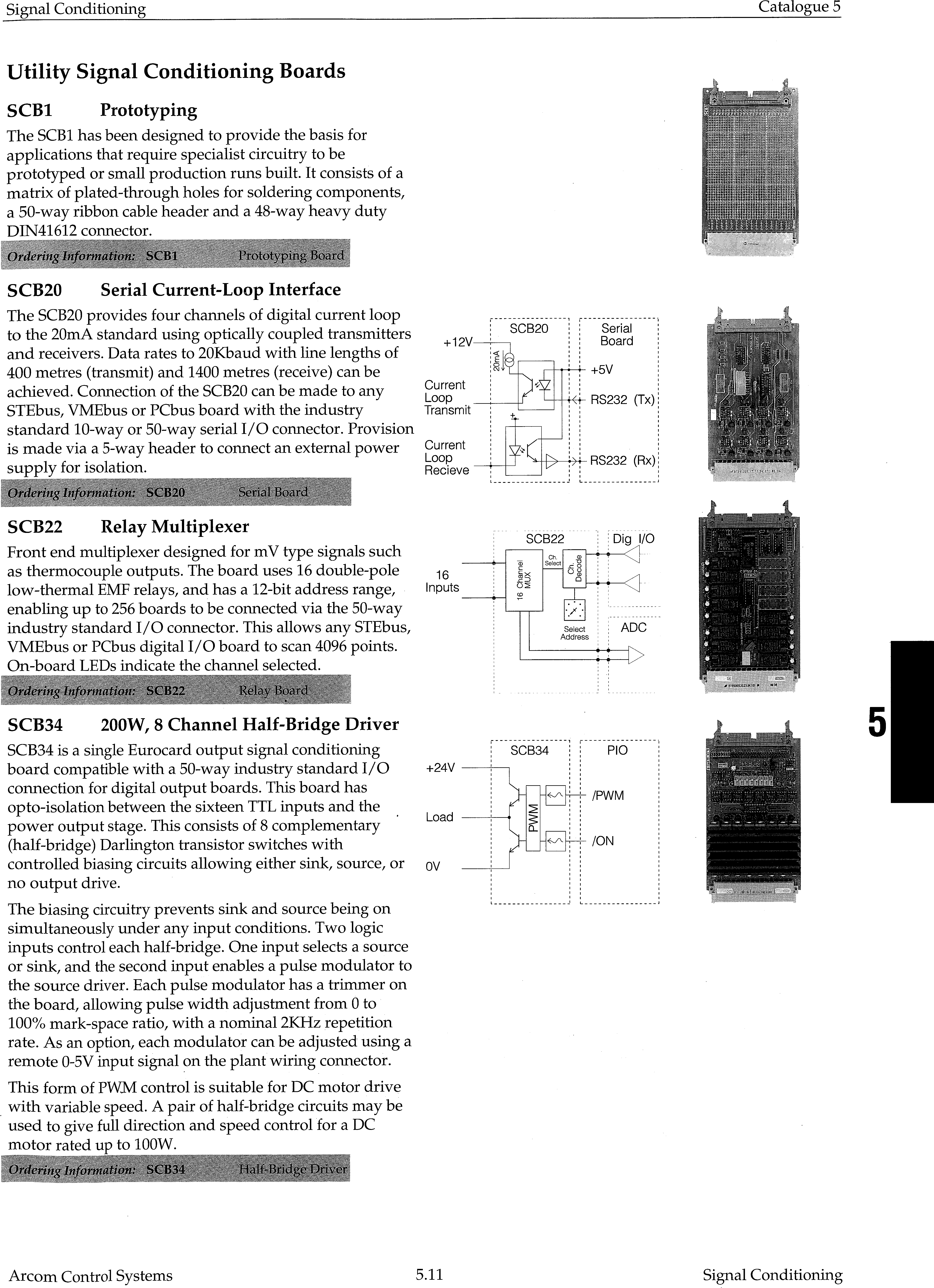
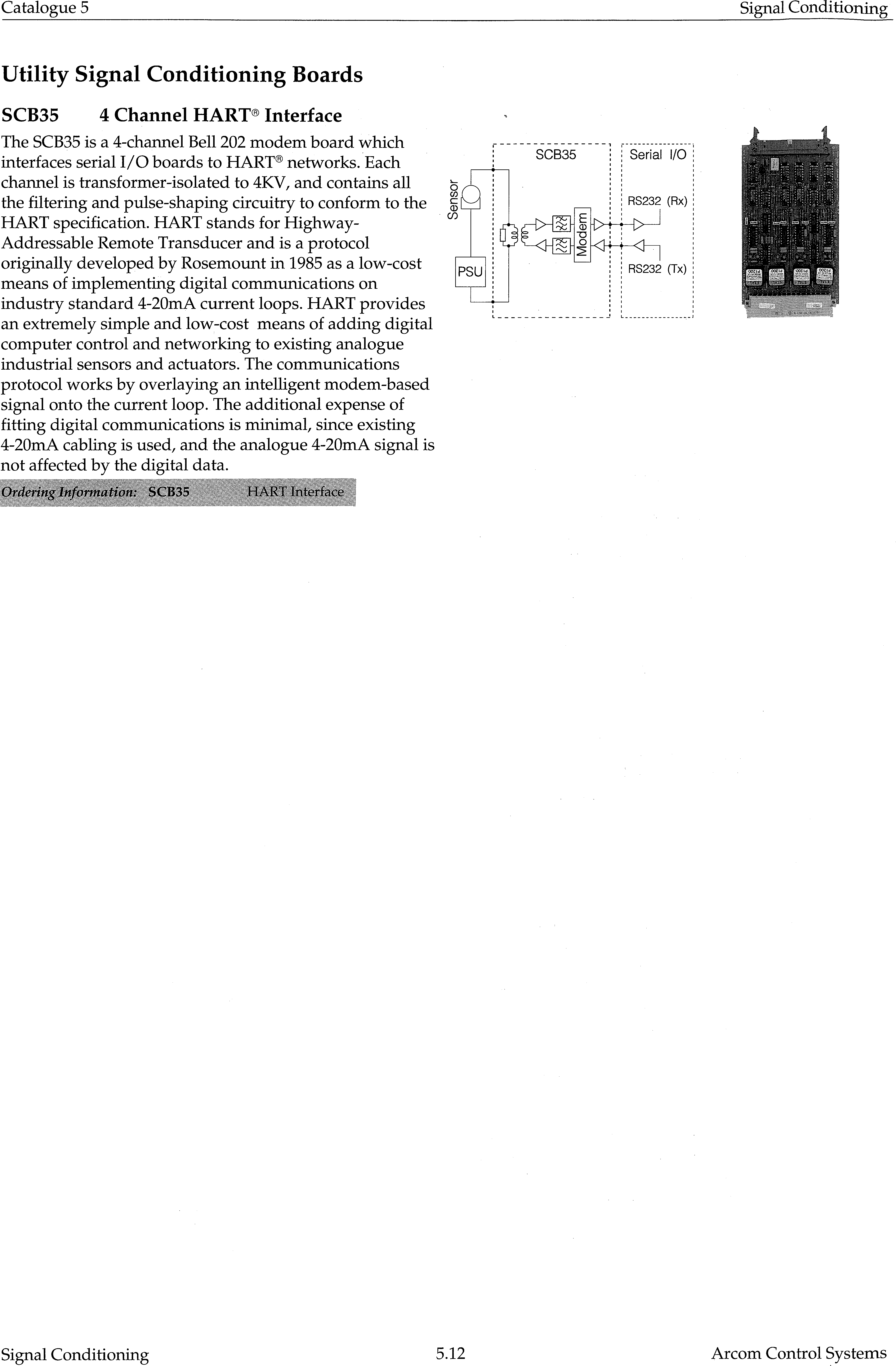
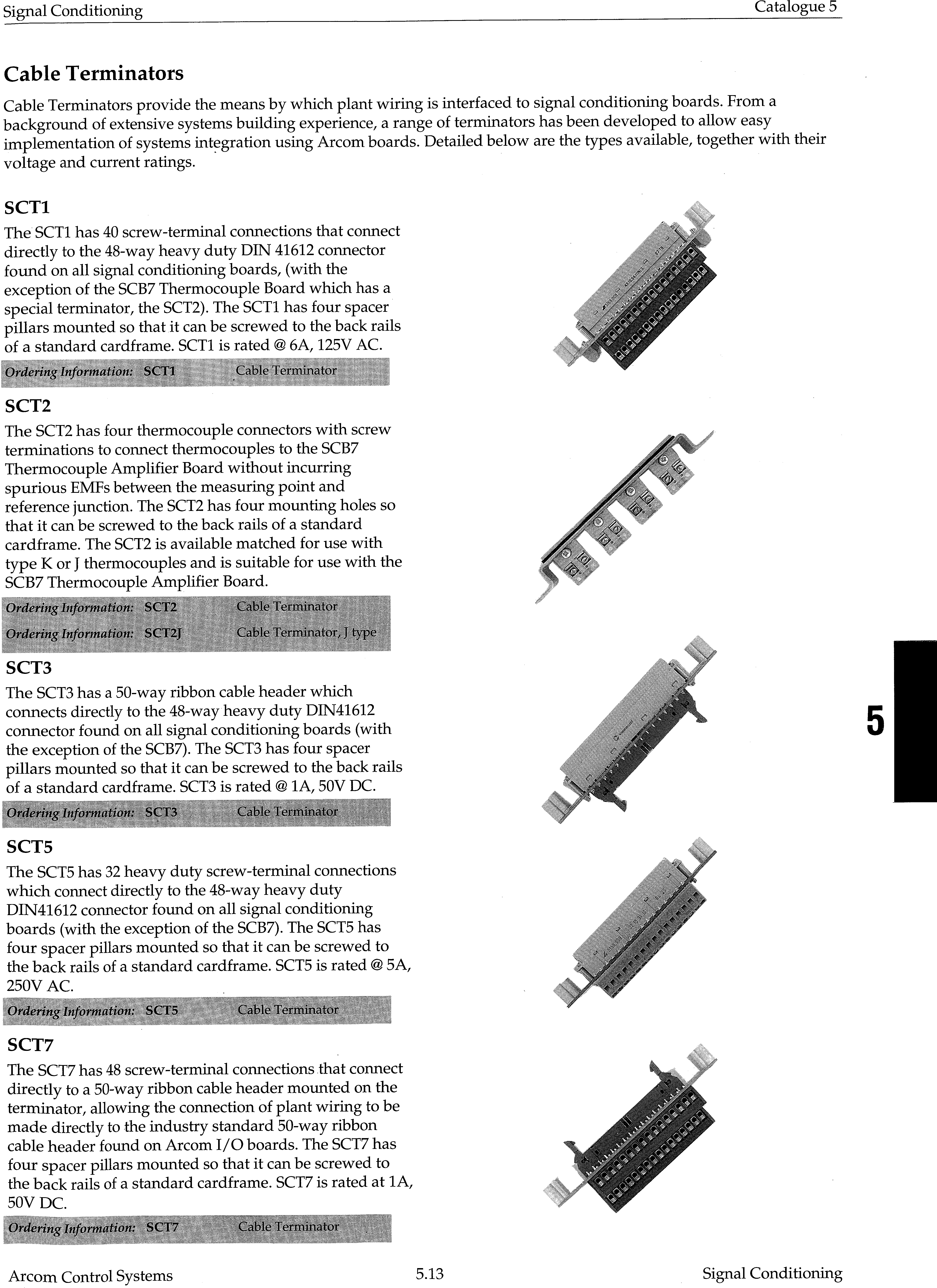
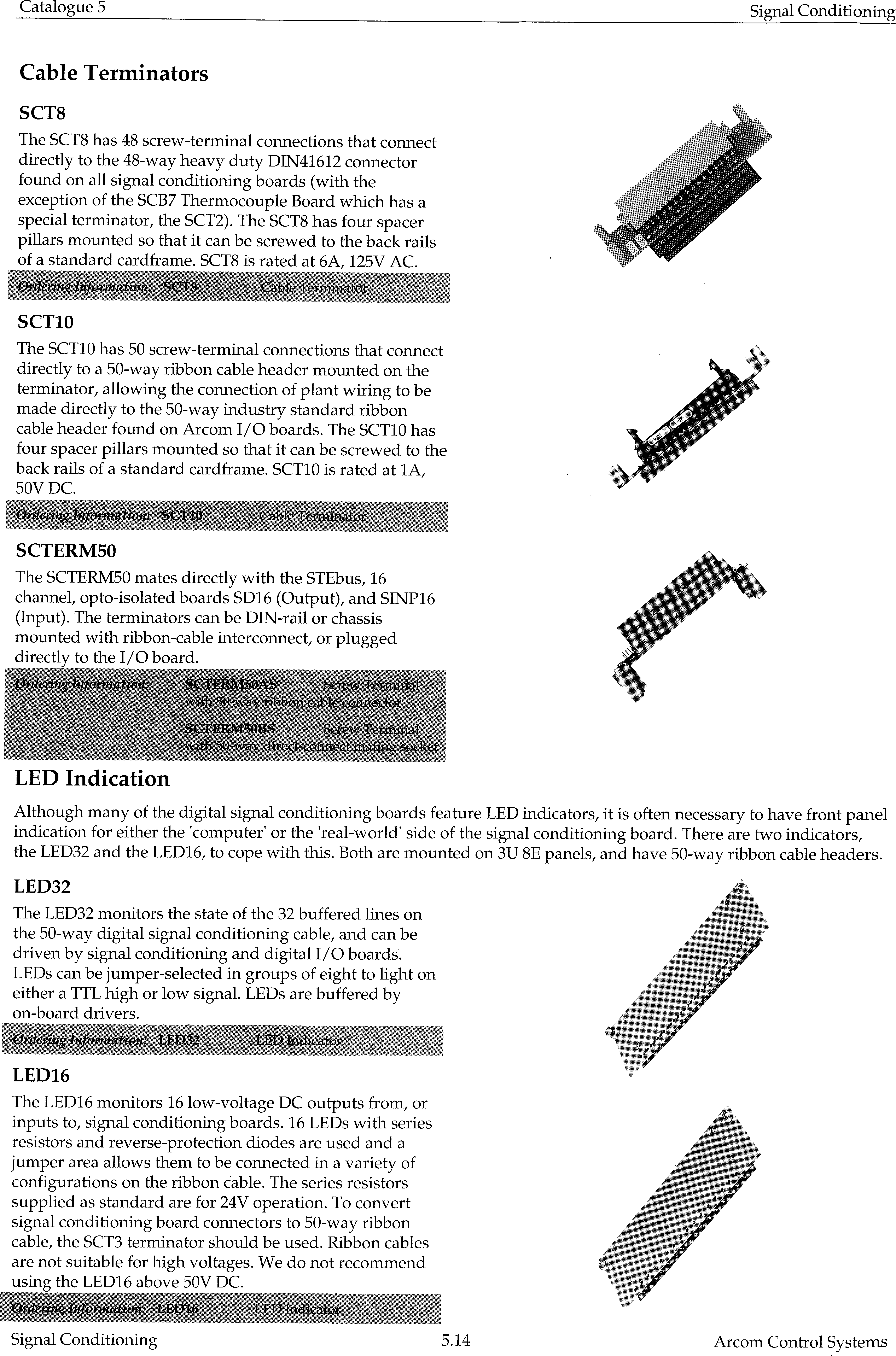
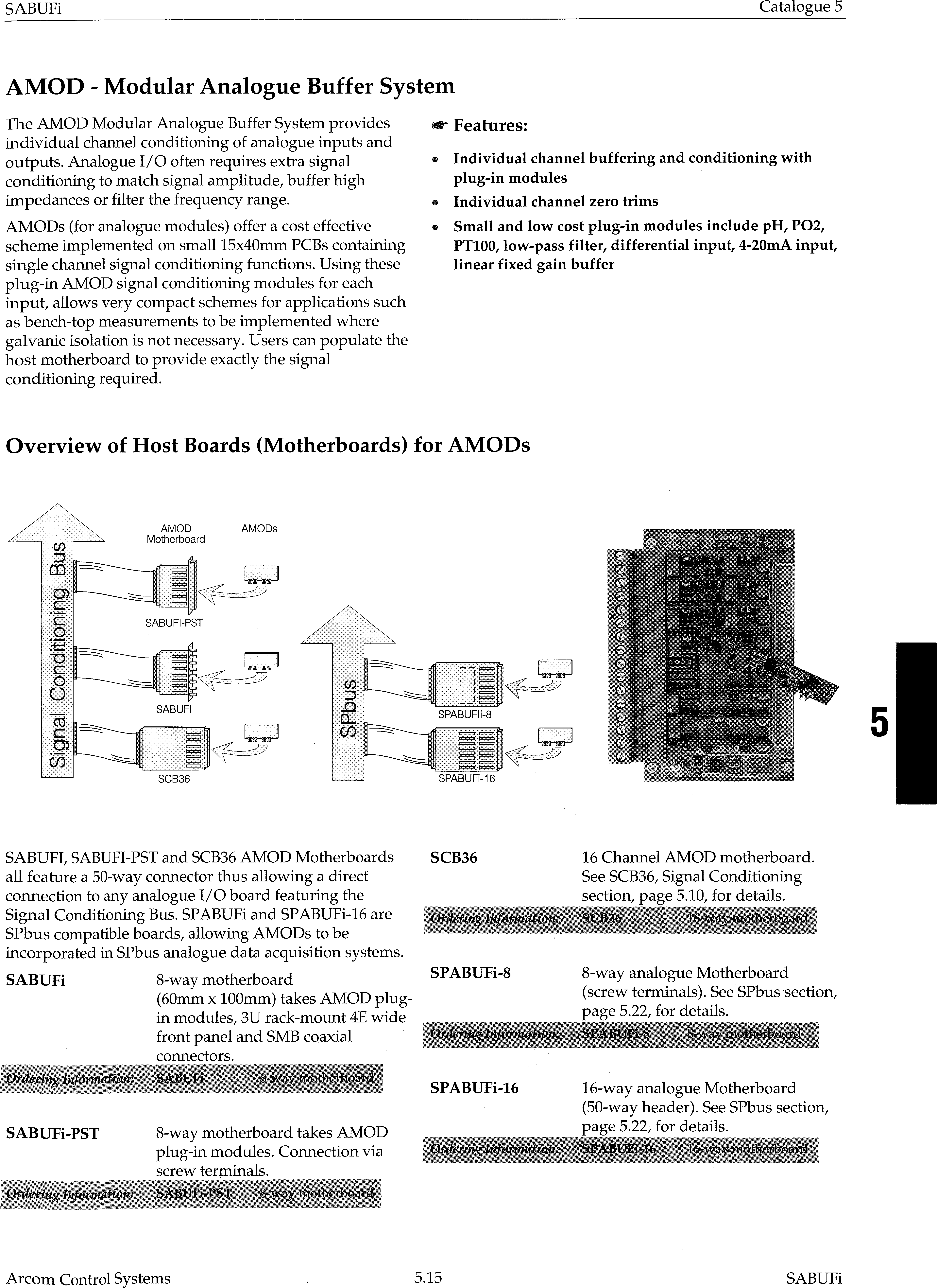
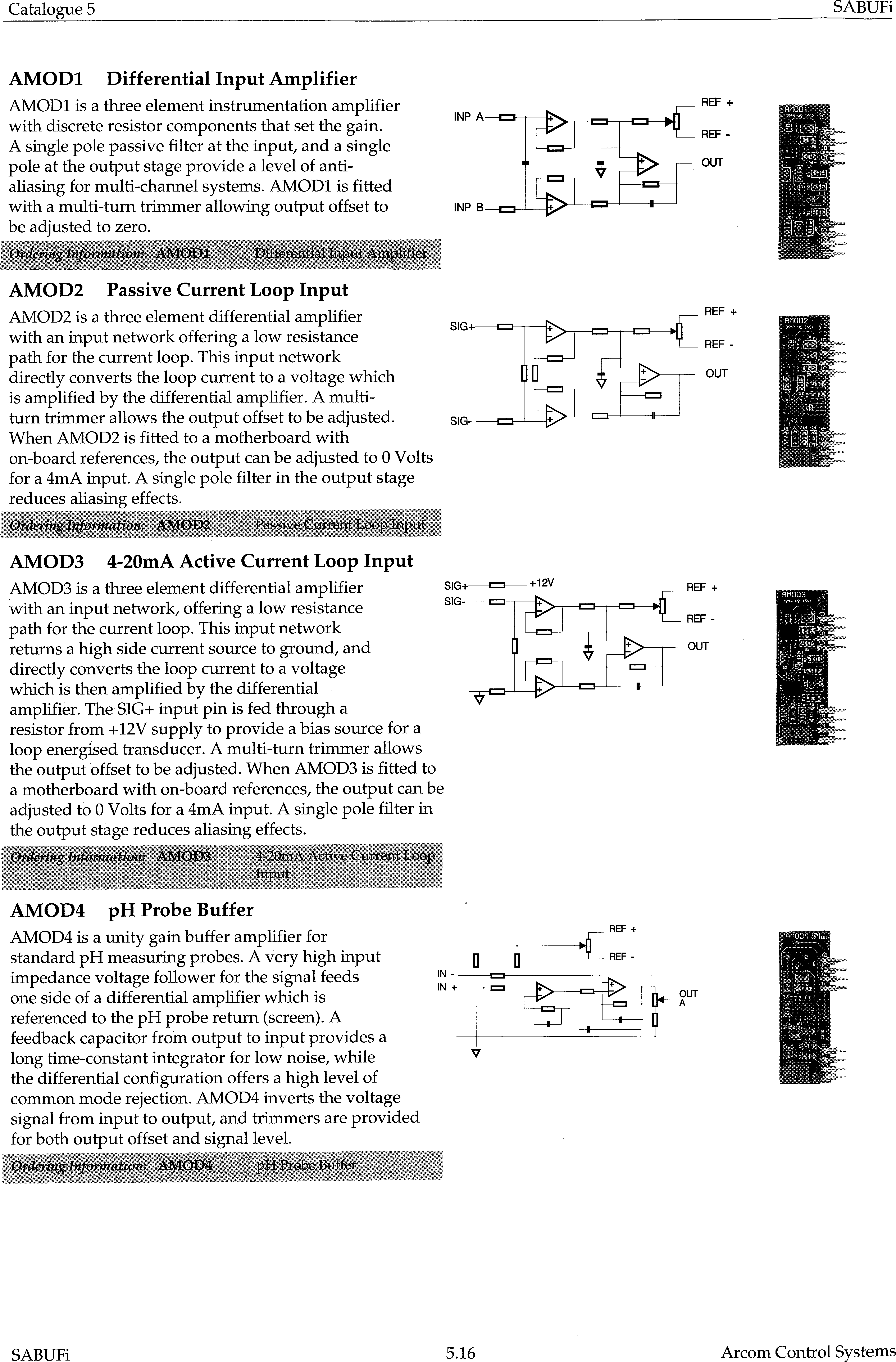
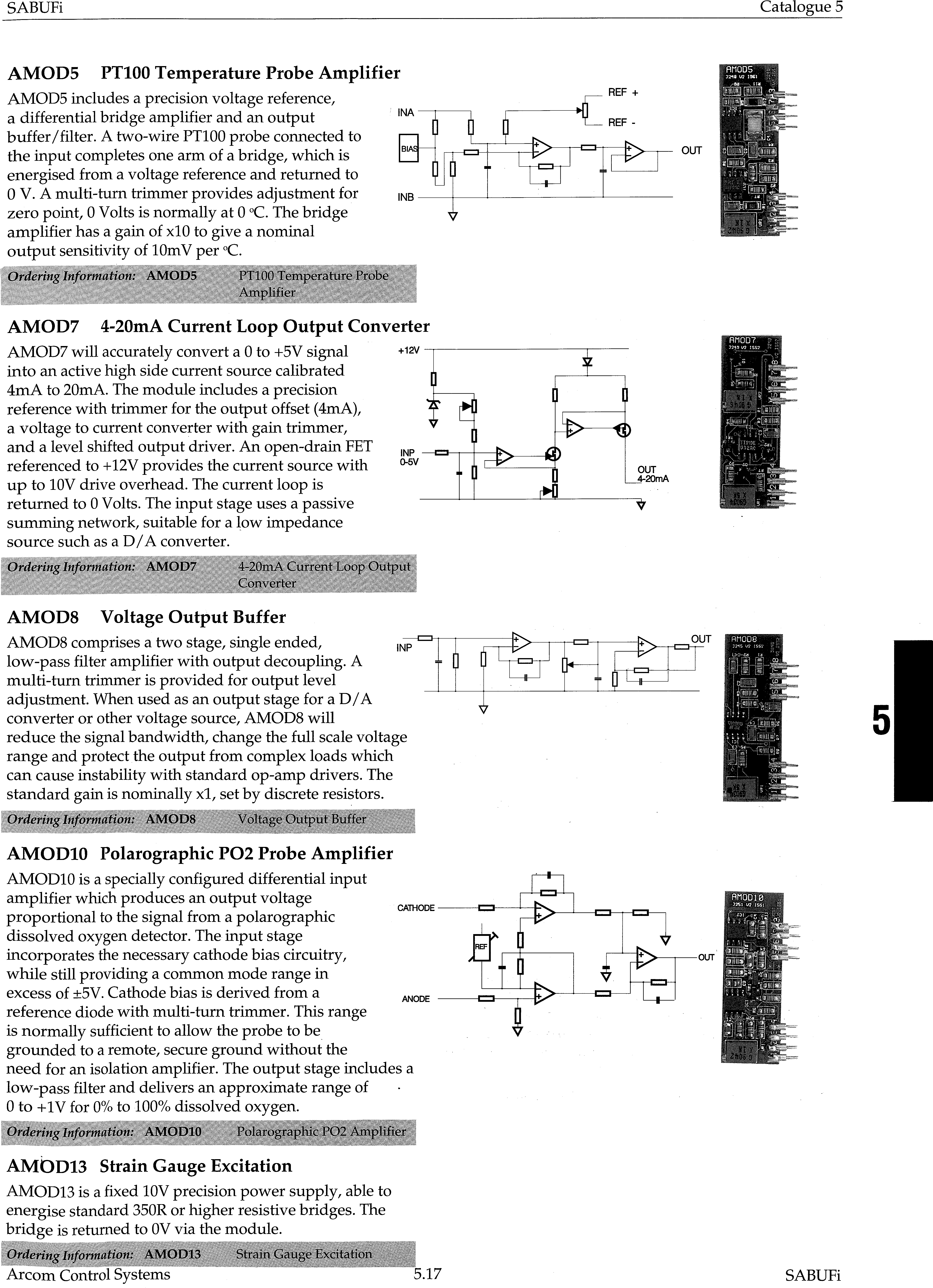
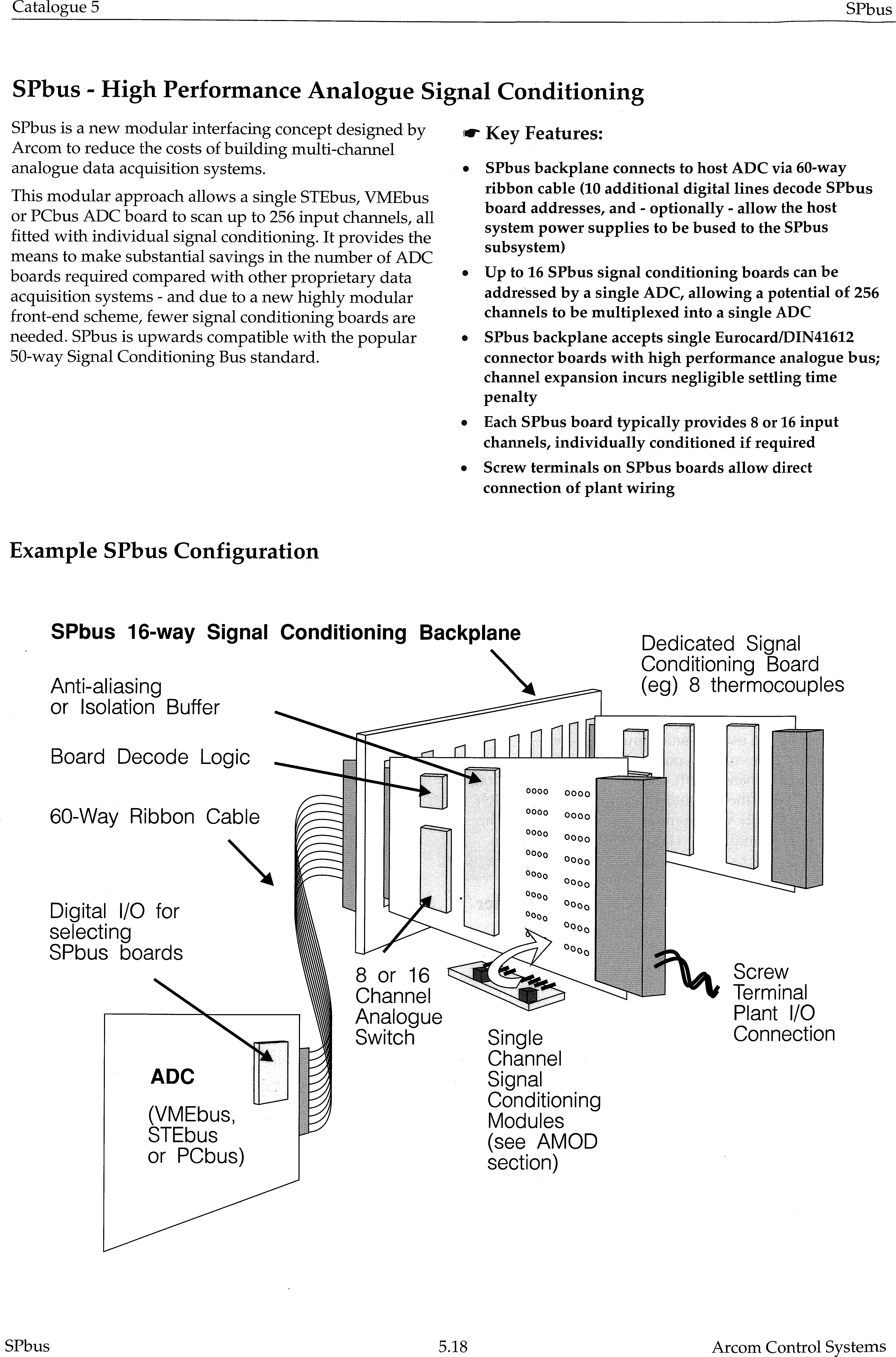
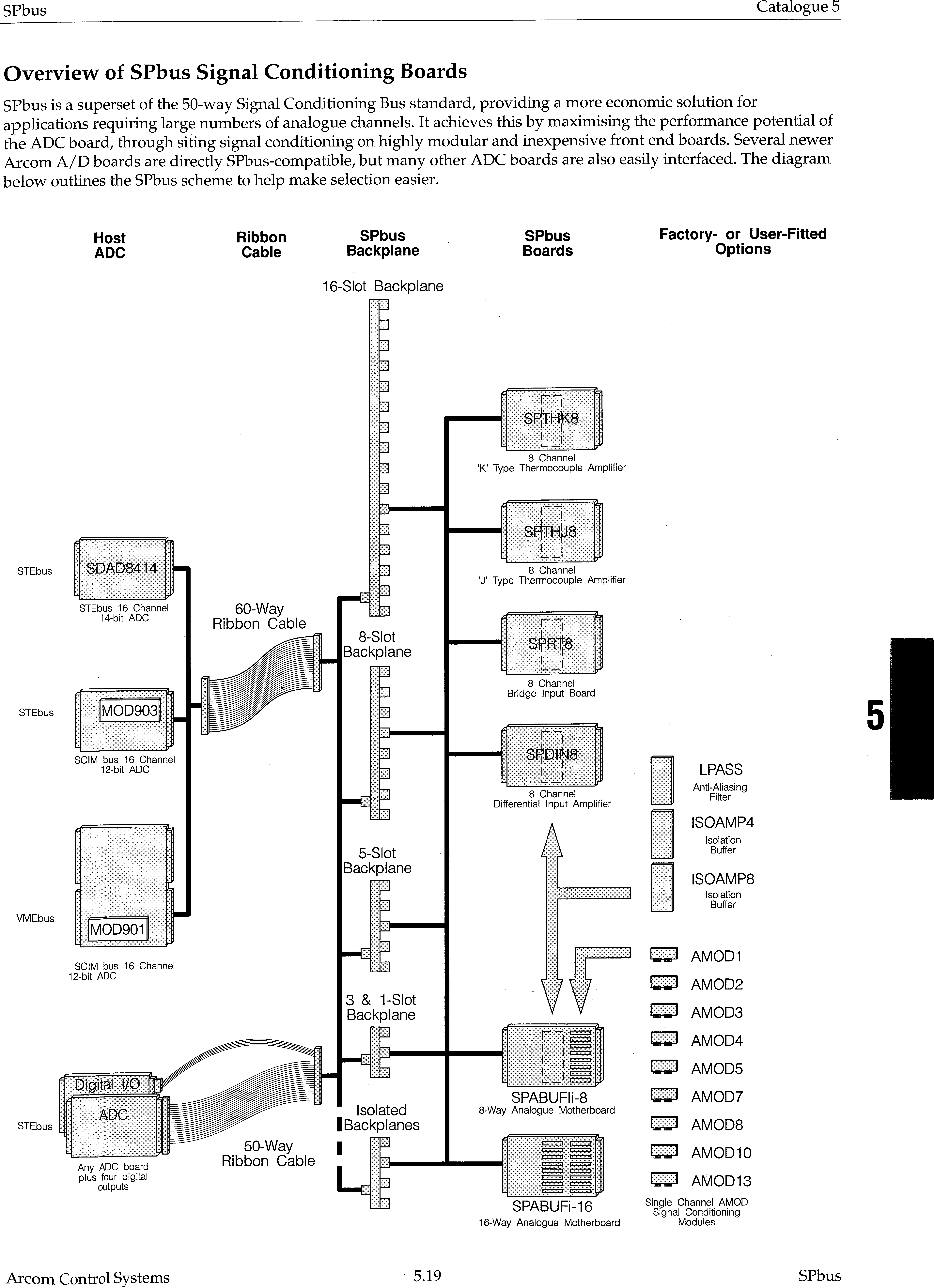
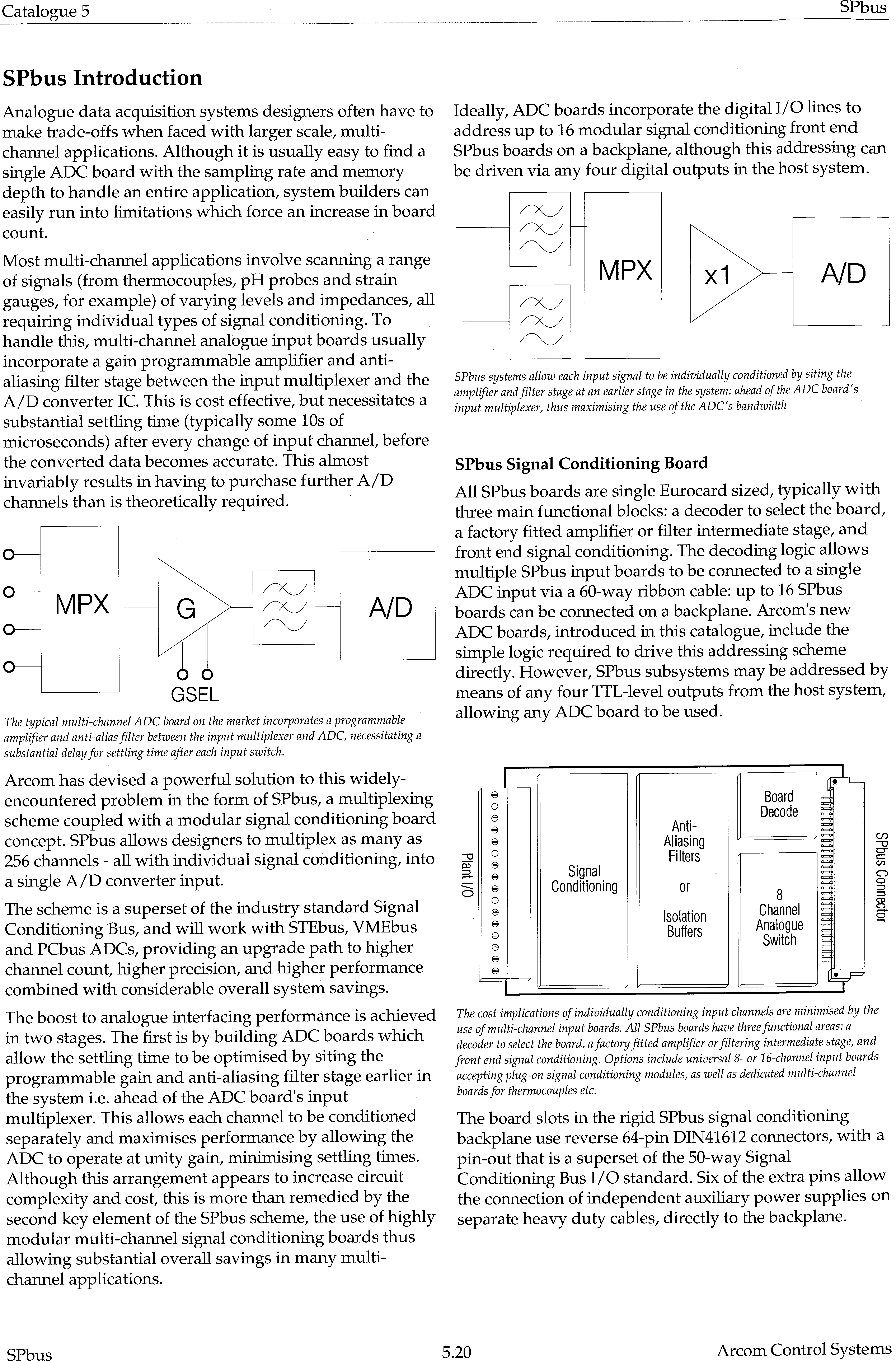
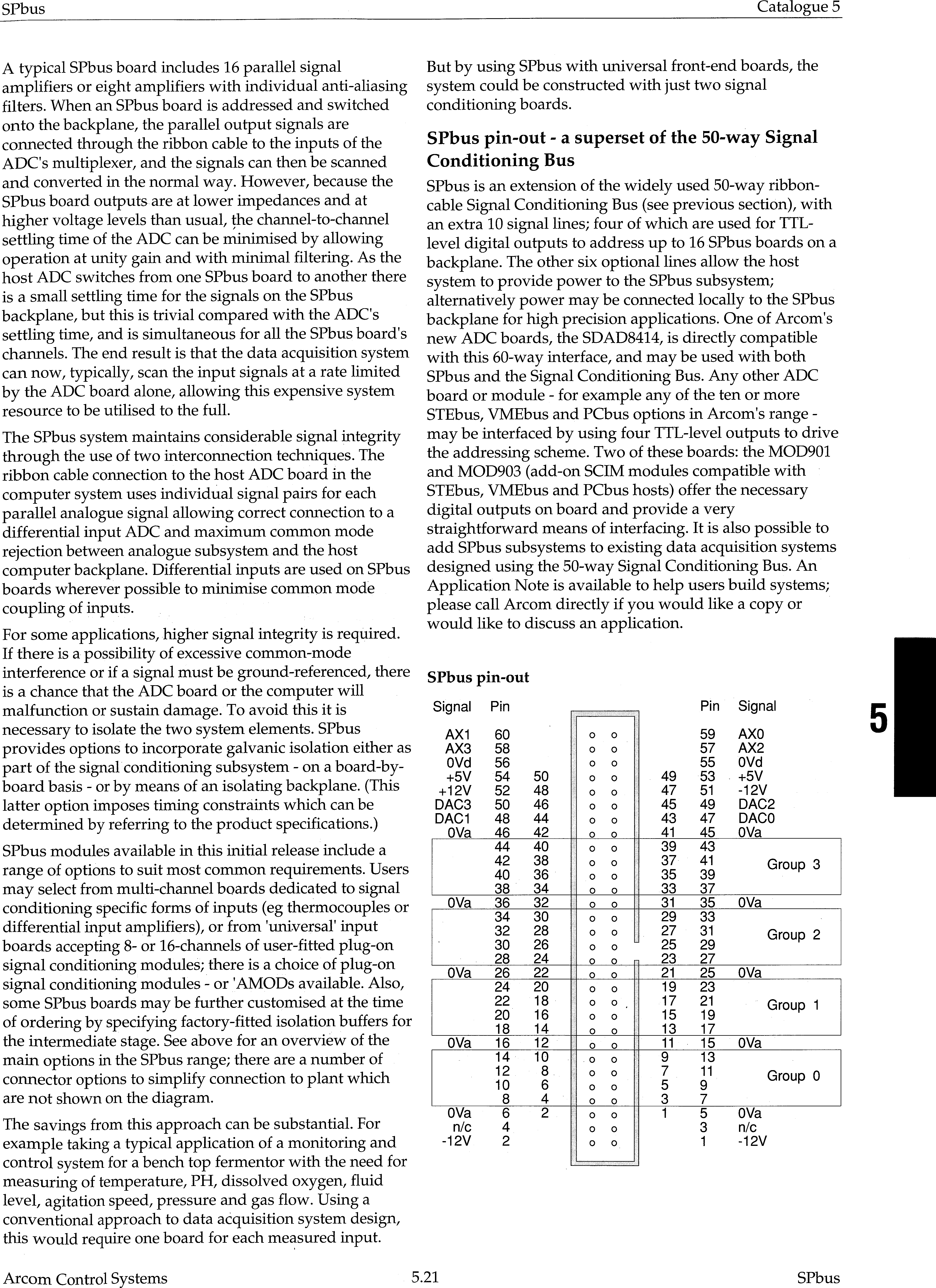
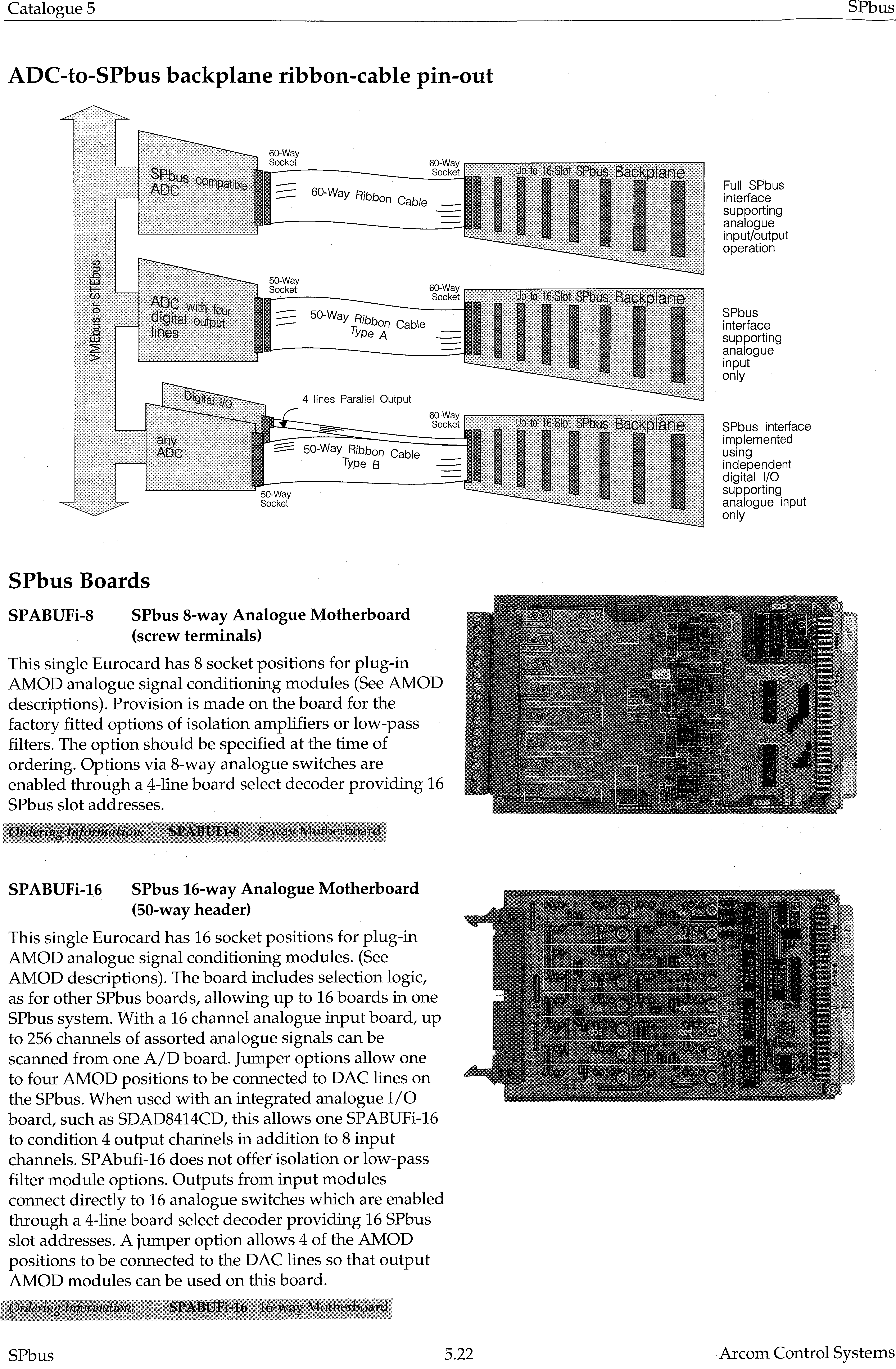
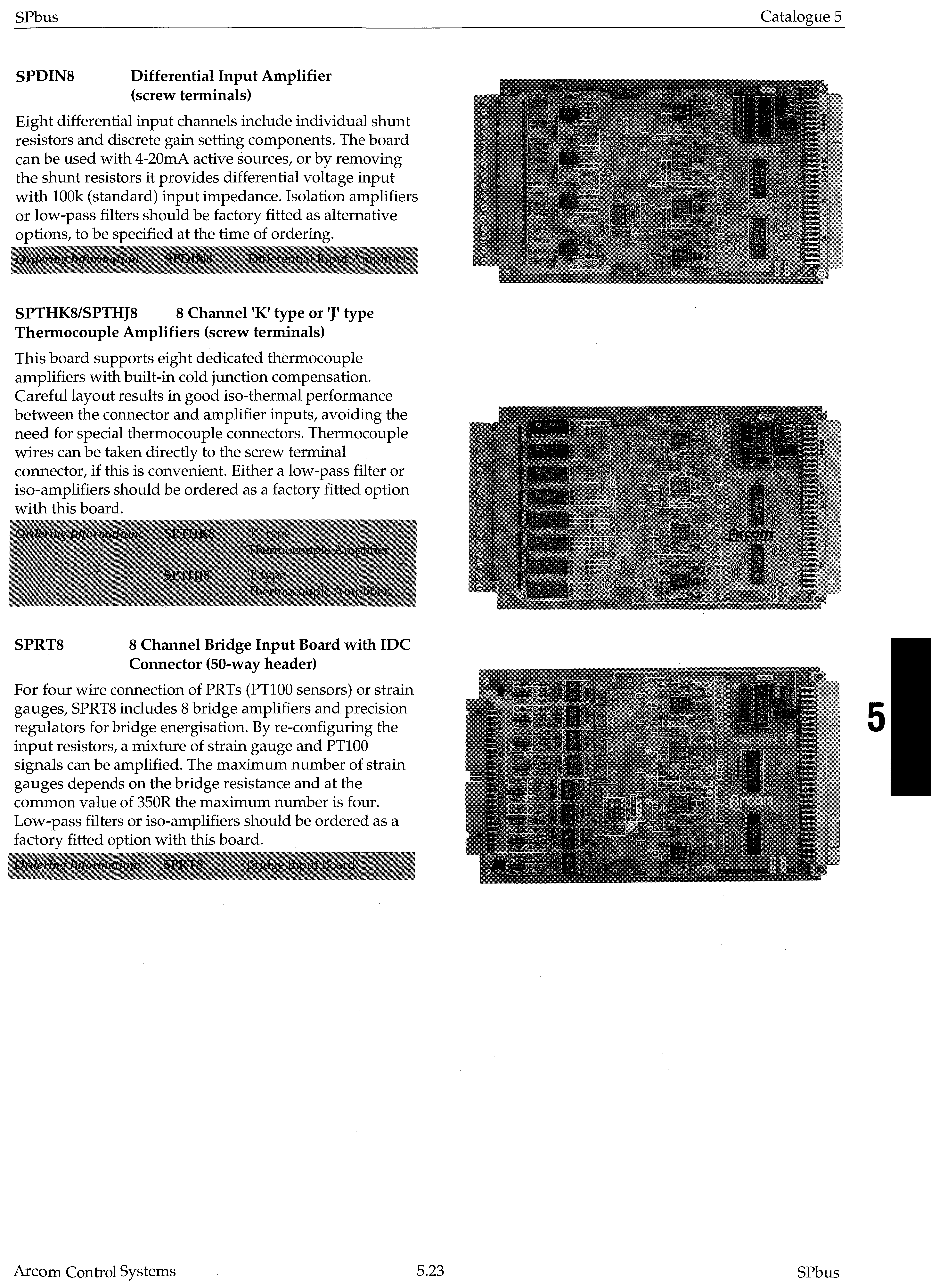
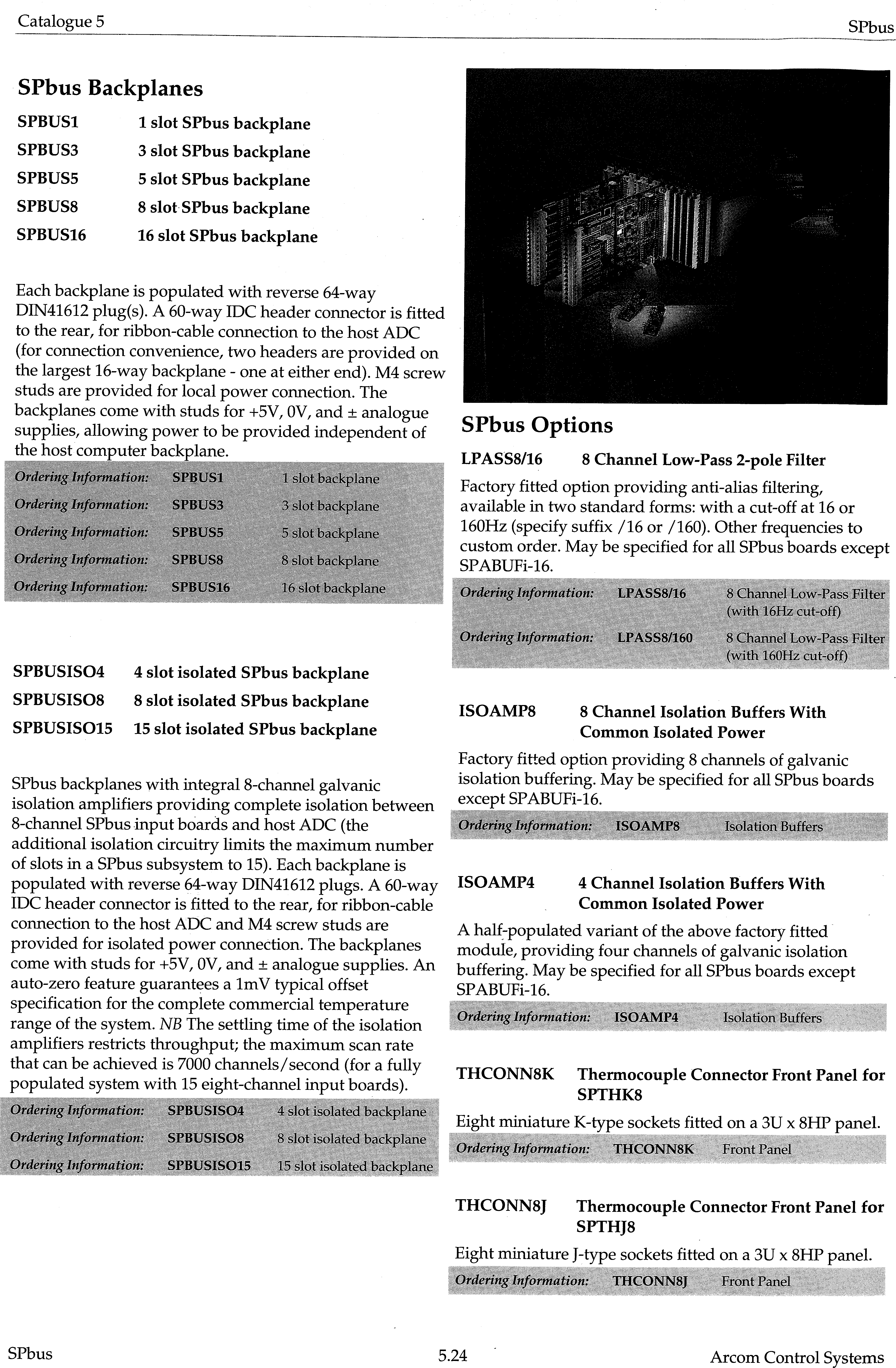
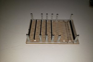
Copies of catalogue pages show the wide range of signal conditioner boards that were made.
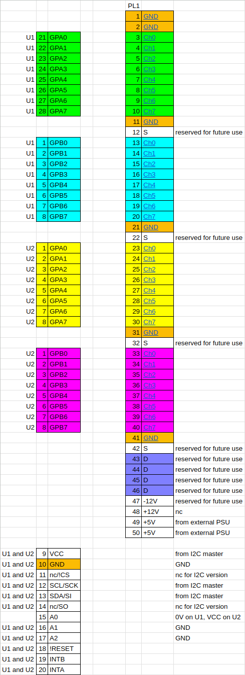 I think the only "loose ends" are the interrupt signals, if used.
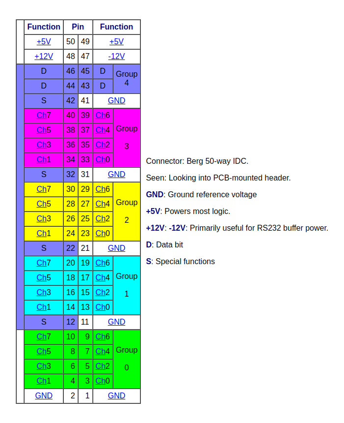


 Stefan Lochbrunner
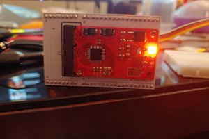
 FloppidyDingo