So, given that prototype v3 has been on my table for a while and I've managed to mostly make it work, the time has come to go through the 'current sensing analysis' ritual.
What is this all about? The crucial functionality of the servo is its ability to sense the current flowing through the motor. If this feature has bugs or doesn't work perfectly, none of the control loops will function properly either. Most importantly, it would be difficult to determine that the issue lies with the current sensing and not with something else. (Trust me, I learned this the hard way with previous prototypes.)
To visualize this:

Situation
The first step is to summarize what we are working with. Here's the simplified circuit:

Our H-bridge, DRV8251A, has current-sensing capability, as documented here. What happens is that based on the current flowing through the bridge, current flows from |PROP| to GND. This is what is measured by the MCU STM32H5 for current sensing. We use a 1k resistor R7 as a shunt resistor.
Tom V. also recommended using a 10n capacitor C15 to handle noise. Frankly, this was a bit troublesome for my CS-focused brain, which has a complete lack of EE knowledge. The question is:
Let's say you sense a current from a PWM pulse, how will the capacitor affect the values read by ADC relative to it being absent?
(Yes, this should be easy to answer for any EE graduate, but here we are.)
Math
The current from PROP is linearly scaled with a known fixed ratio: 1575 µA/A
Given that, we can formulate the basic formula:
V_R7 = I_R7 * R_R7
I_R7 = I * COEFF
What we want to know is: given some fixed voltage `V` measured on `R7`, what is the current flowing through the motor?
The answer to that is in the formula: `V_R7 = I * COEFF * R_R7`
Which, once we fill in the known information, gets simplified to: `V_R7 = I * 1.575`
Note that the resistor has quite a resistance for a shunt resistor, but given the drastic ratio between the real current and the current flowing through |PROP|, the values cancel each other out.
Baseline
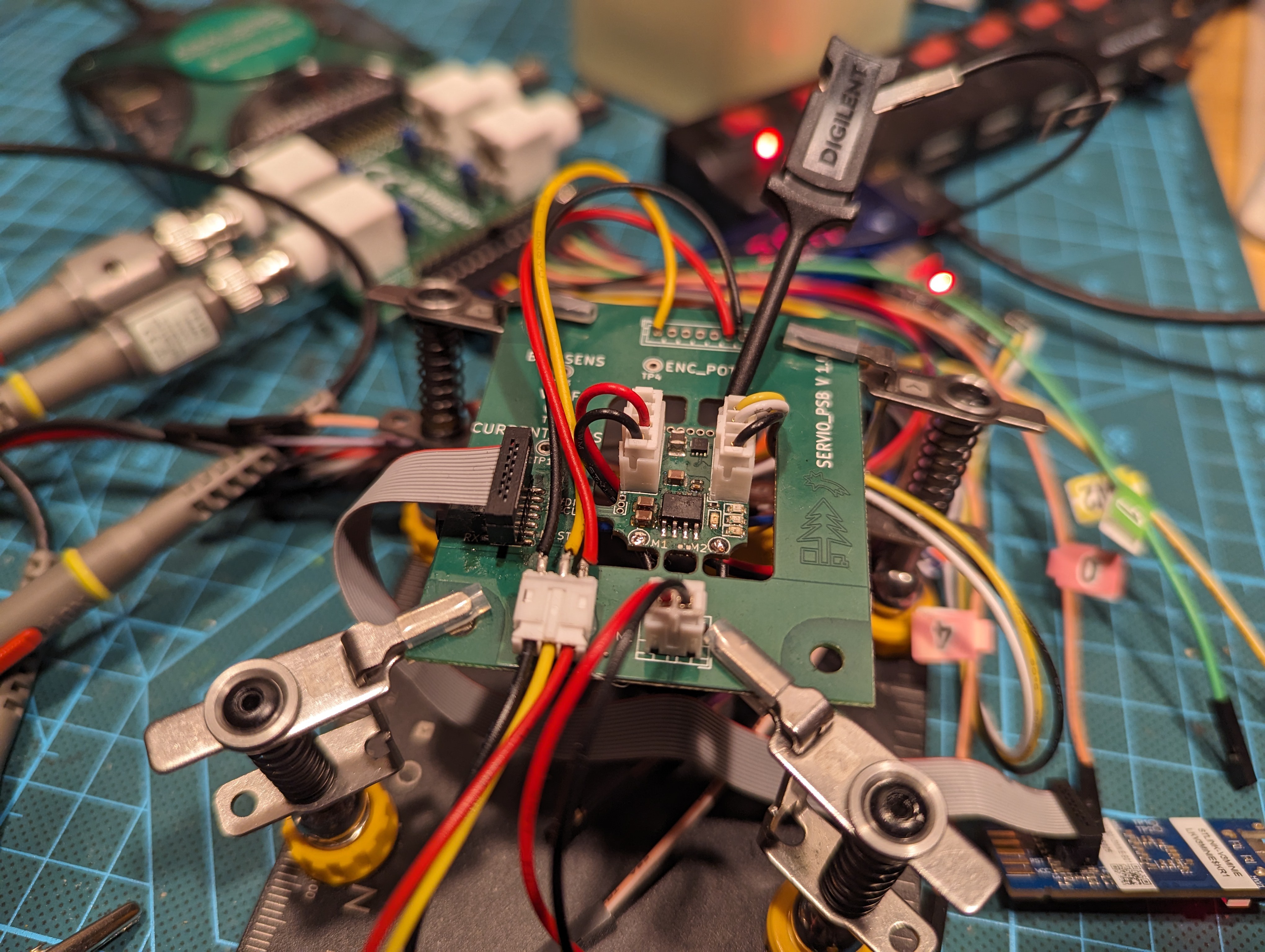
Given that we know this, let's take a scope and measure some things. What we can do is attach a motor to the servo, flash the production firmware, and use a control utility to set the servo to a fixed PWM duty cycle.
The motor is a scrapped Lewansoul LX15D. Since the motor was without any load, the expected current values should be low, as without resistance it won’t need much.
My trusted laboratory power source is powering all of this. The power source has the capability to measure current, so I relied on that for comparison values.
There are multiple scenarios during which I've taken data. In all cases, I relied on the Analog Discovery 2 for the measurements, as that device is my daily tool for such tasks. As you can see, I can even make fancy screenshots of the view from it :)

The interesting data is on Channel 2, which was attached to the current sense pin—effectively connected to the PA4 pin of the STM32H5 on the circuit above. I also made sure that I could observe the PWM duty cycle on the logic analyzer of the AD2; you can see it in the bottom row. (14kHz PWM frequency is about right)
Channel 2 gives us the voltage across the R7 resistor. I've also added a virtual channel,`Math 1`, that converts the values from Ch2 into the actual current flowing through the motor.
It should be noted that the current reported by the power source includes the power drained by the MCU and other peripherals, not just the motor, and at this point, there is no way for me to separate them. However, it should be manageable.
After all that was done and prepared, I measured relevant values for multiple scenarios. Note that I always used the `average` value for each channel:
| power | 0% | 25% | 50% | 75% | 100% |
| power source current | 11 mA | 31 mA | 57mA | 81mA | 106mA |
| R7 voltage | 18 mV | 50 mV | 155mV | 177mV | 224mV |
| calculated motor current | 12 mA | 32 mA | 98mA | 112mA | 142mA |
What do the measured values mean? I have no conclusions yet, and frankly, I would prefer to consult this with someone more skilled in EE to ensure that I'm not missing something. The interesting observations are:
- I have no clue how well my power source or the AD2 is calibrated.
- The MCU and other non-motor-related components might be consuming around 11mA, which seems reasonable.
- The voltage on R7 is increasing at a faster rate than expected—the current at 25% is identical, but at 100%, it is 106mA versus 142mA. This might suggest that the current-scaling constant for the H-bridge differs significantly, but that is not entirely unexpected. But, what if the capacitor in the circuit is causing some issues?
- For some reason, the voltage on R7 when the power is at 0 is non-zero.
Out of all of this, only point 4 is troubling me, as it might disturb the control loops more than I would want.
Time to bother my friends and ask them some questions!
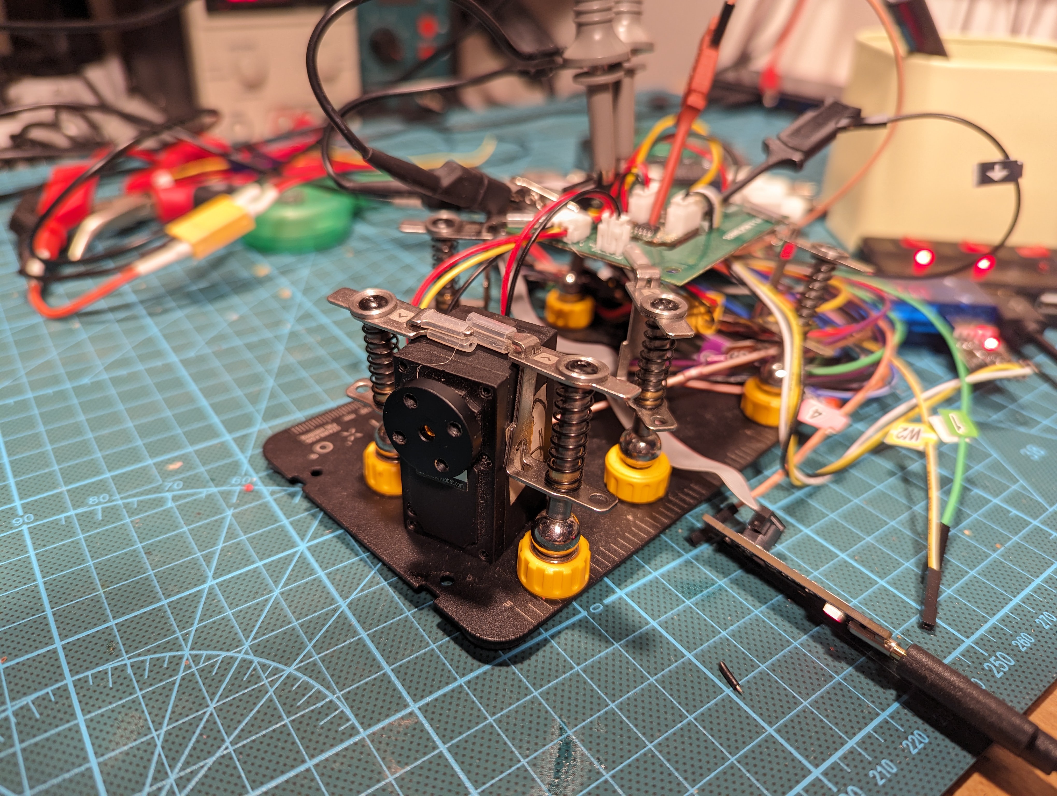
More photos

Discussions
Become a Hackaday.io Member
Create an account to leave a comment. Already have an account? Log In.