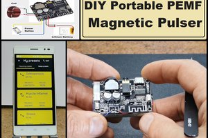
mircemk
At the request of several of my subscribers, I decided to explain to you how you can make such an instrument yourself. The device is extremely simple to make and represents the most common oscillator whose frequency of oscillation depends on a given resistance. In this particular case it will be the resistance of our skin. I want to remind you that I will not at all explain the way of diagnosis using this method, but only the technical part, that is, the way of its production.
The basic version of this device was made at the end of the last century, so some parts are hard to find nowadays, so I will make it with modern components. The most difficult to obtain is the output audio transformer, which was used in small portable radios manufactured in the last century. Instead of original, I'm going to use two audio transformers, each with a winding ratio of 8000:8 which can easily be bought online and the price is less than 2 dollars for 5 pieces.
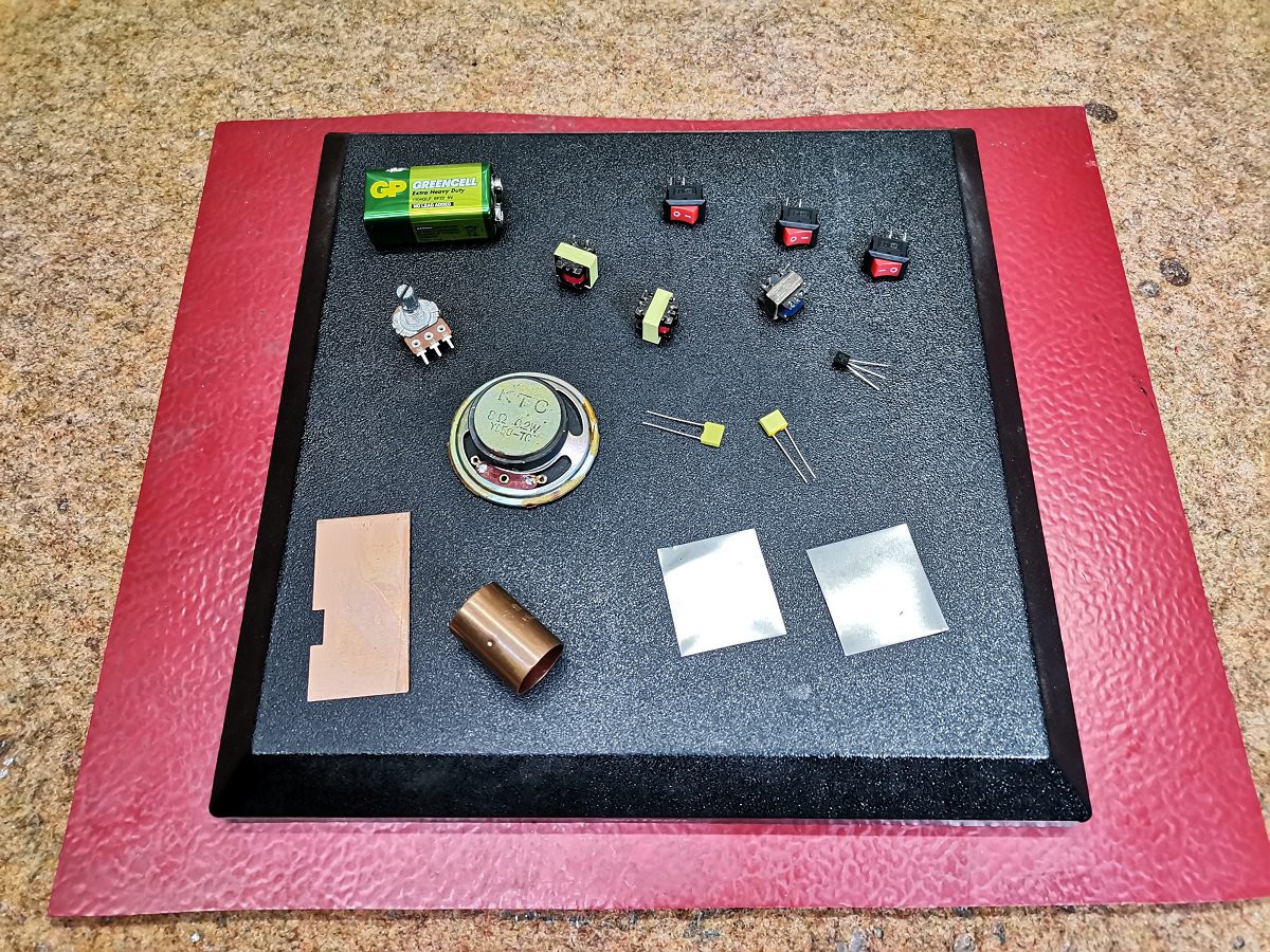
The other parts of which the device is composed are:
- Universal PNP transistor, I will use the BC 557, but any small signal PNP transistor can be used without any circuit modifications.
- 8 ohm small speaker
- 50 Kilo ohm Potentiometer
- two capacitors
- 2 metal plates wicah a actually open capacitors
- Probe (I use one electrode from a multimeter)
- handhold usually made from a piece of copper or other metal rod
- Small power amplifier or active PC speaker
- switches
- and battery
If you want to make a PCB for this project, or for any other electronic project, PCBway is a great choice for you. PCBway is one of the most experienced PCB manufacturing company in China in field of PCB prototype and fabrication. They provide completed PCB assembly service with worldwide free shipping , and ISO9001 quality control system. Also, on their site there is an online gerber viewer where you can upload your gerber and drill files to render your board.

I made the device in as simple a way as possible so that it is understandable for more viewers and so that even those with relatively little experience in electronics can make it. First we need to determine the primary and secondary winding of the transformer. We will do it most easily with the help of a multimeter, since we measure the resistance. One side has a resistance of about 90 ohms and that is the primary, the secondary side has a resistance of only a few ohms.
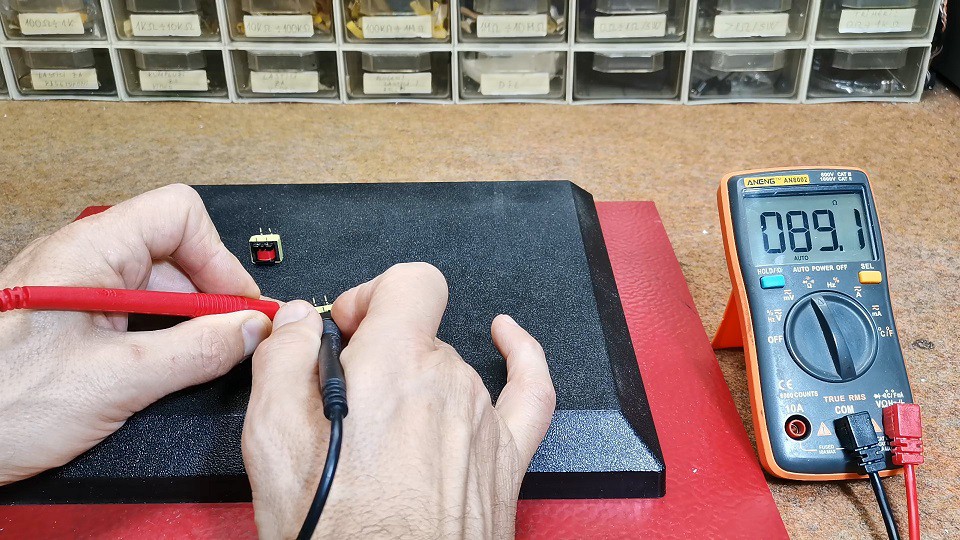
To get the mean derivative of the primary winding, we need to connect two such transformers in series as shown in the schematic diagram. The impedance of this type of transformer is significantly higher, so the value of the capacitors is lower compared to those of the original, in order to obtain the same frequency at the speaker output.
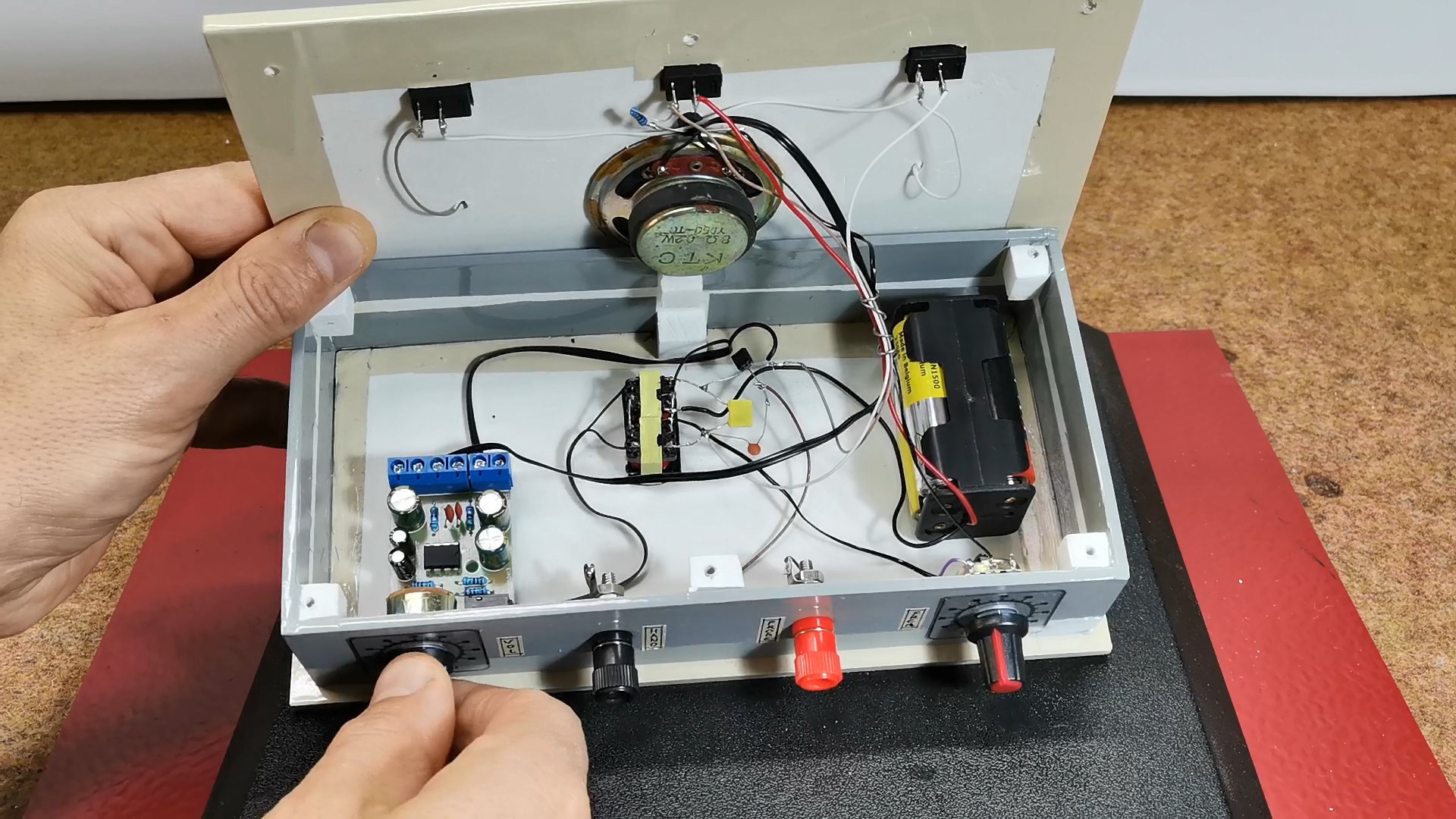
And now let's look at what's inside the box:
- The main circuit consist of Trafo, two capacitors. transistor and Potentiometer
- Small Power Amplifier board with Speaker
- Two metal plates connected to the main circuit via switches
- 6V Battery pack
- handhold and probe connectors
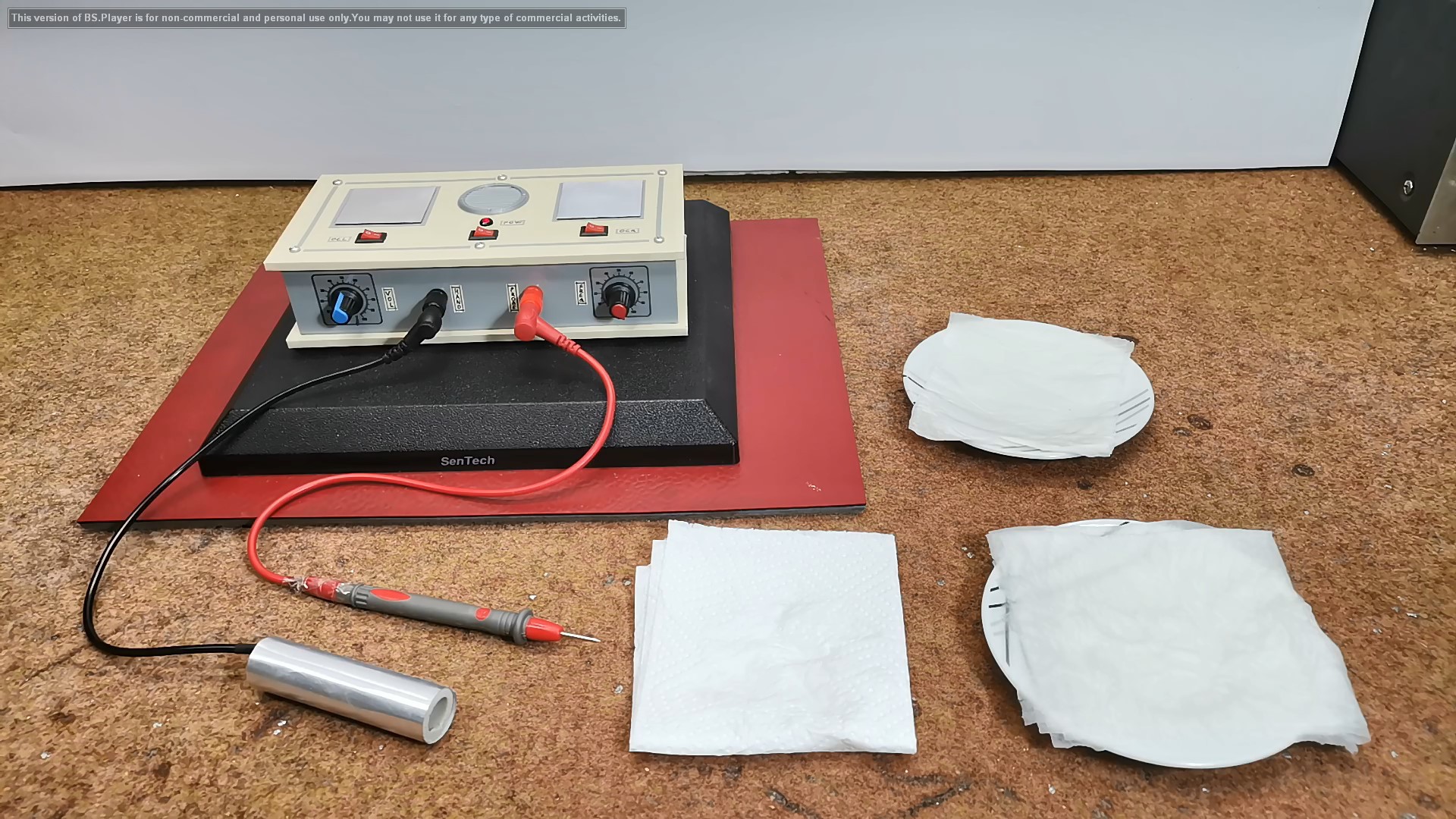
First we need to test if the device is properly made and working. We connect the handhold and probe electrodes and turn on the synchrometer. Next Turn the control knob clockwise to nearly the maximum. This reduces the resistance to nearly zero. We can test the circuit by briefly touching the probe to the handhold. The speaker should produce a sound like popping corn. Test plates which serve to put test substances and tissue samples on it. The wiring in it is arranged so that you can switch in either one of the two plates.
We test their functionality in the following way:
Turn on the first switch and Touch plate with the probe, while holding the metal pipe with one hand. We shoud listen soun from the speaker. We repeat the same procedure for the other plate.
Now that...
Read more »