 Marek
MarekSystem is meant to be design in modular way where different modules provide functionality for multiple use cases. Nevertheless to have some real world scenario in mind will help me validate the idea and make first steps.
Use cases:
Shutter Controller [DONE]
First thing I have in mind when building the system is shutter, roller or curtain controller.
I have 4 wire electric curtain motor that use main voltage to either close or open curtain (cables are forward, reverse, natural and PE).
Functionality required:
- I am not sure if there is a protection against providing main onto both forward and reverse so I want my system to provide mechanical protection for that.
- Obviously buttons should be supported
- In winter time when heating is on I want curtains to be closed over the night
- In summer when light is operating I want to close them to block excessive heat from getting to my house. It should follow the sun direction (it can be calculated) and sun strength (based on photovoltaic production) so curtains are closed only when necessary and open otherwise.
- Naturally I want that it is connected to Home Assistant system that I have but I want it operates standalone as well
Modules that will be needed:
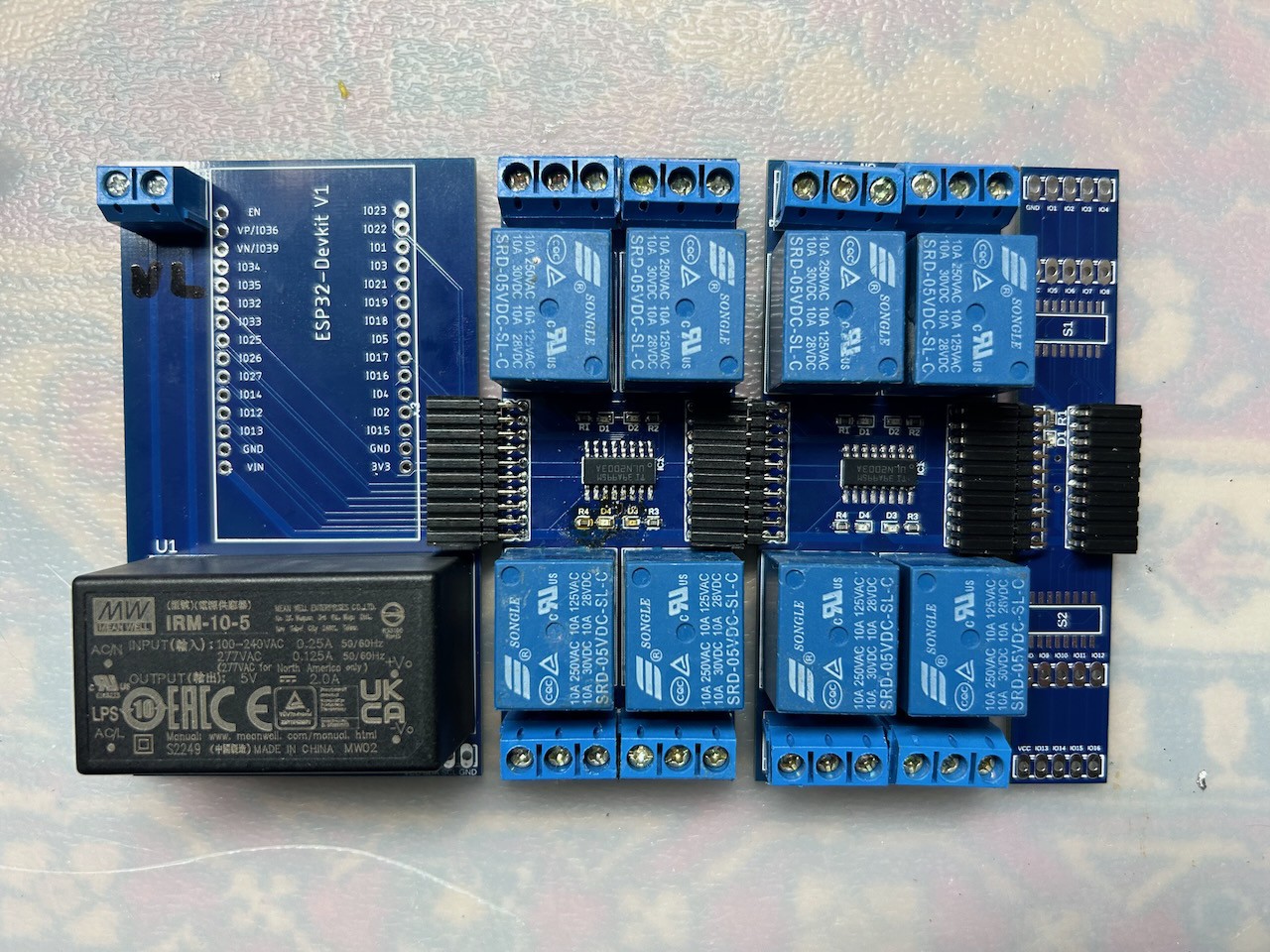
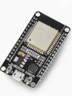
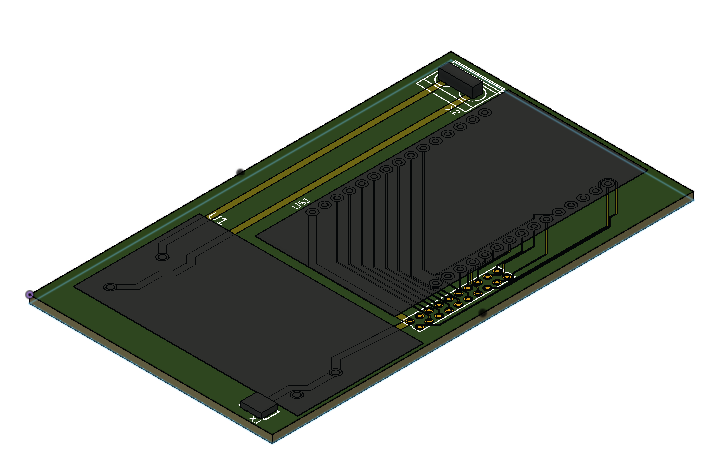
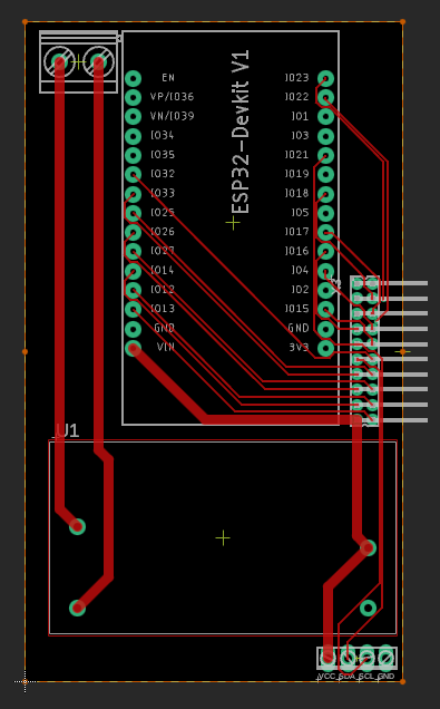
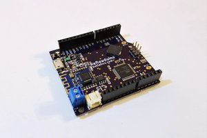
- ESP Board
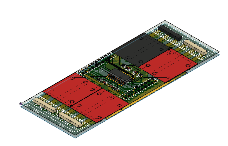
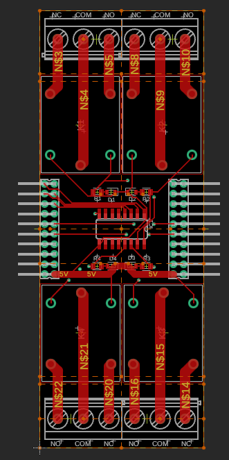
- 4ch Relay
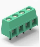
- Terminal Block

Irrigation Controller [planned]
I just want to control 24V on/off valves from ESP connected to hassio. Hassio will be providing all the intelligence as of when irrigation should be on based on weather forecast.
Theoretically it can be done with existing 4ch Relay module but I'd rather have something that provides more channels in smaller size as I don't need no/nc connection there.
Modules that will be needed:
- ESP Board
- [NEW] Solid State Relay
Dimmable Led Light Controller [in planning]
That will be next big challenge as I want all my lights to be controlled with dimmable module. I already now that it will not be easy as I have tried already several approaches I am not satisfied at all.
Assumptions:
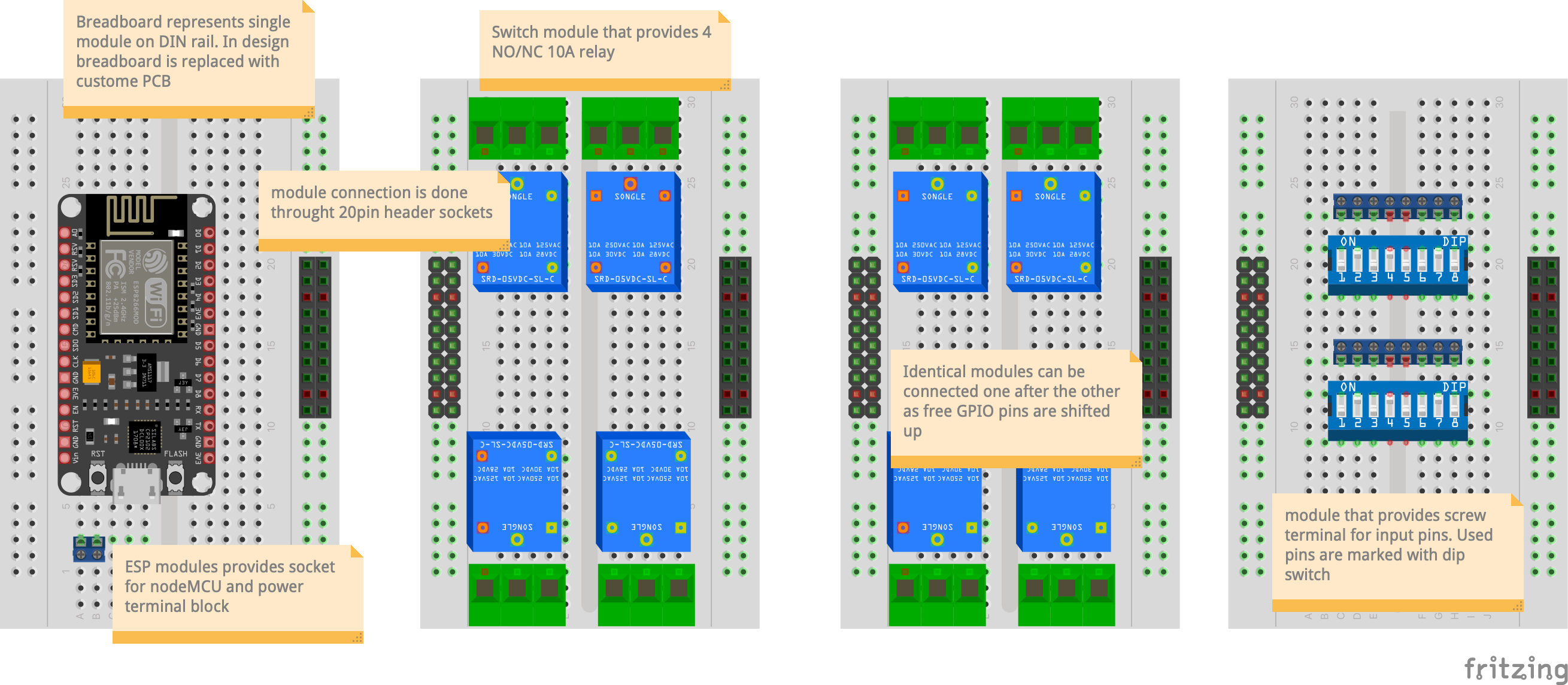
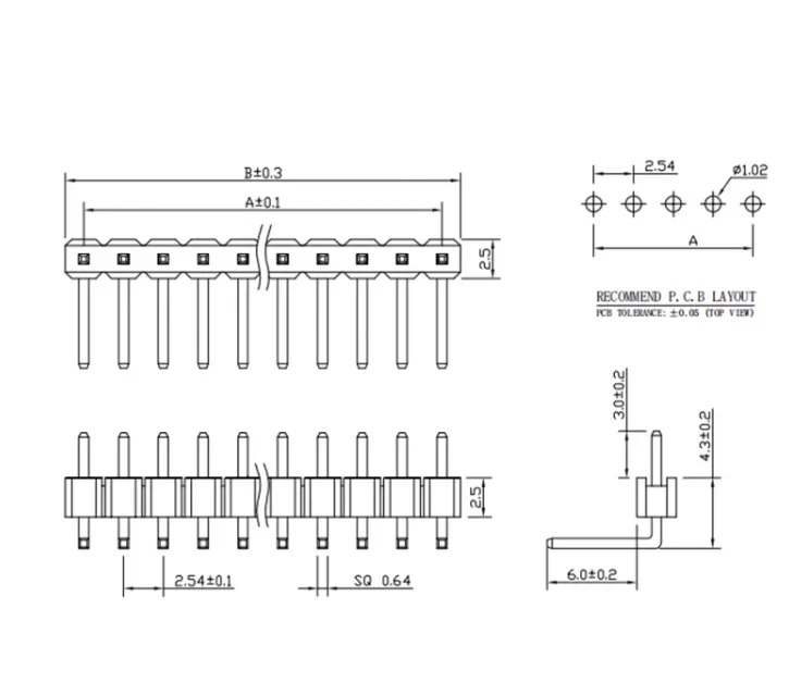
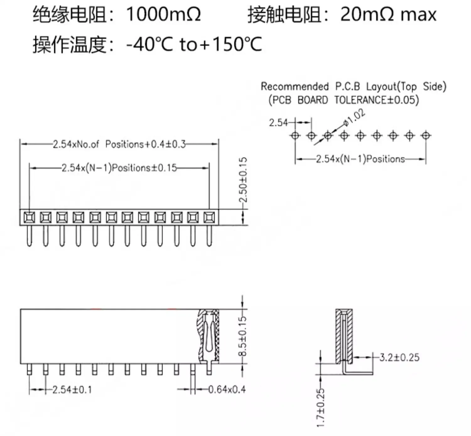
- modules interconnection should be realised as board to board connection
- it should be possible to mount modules on DIN rail, standard module width of 18mm should be taken into consideration during design
- whole solution should be compatible with ESPHome
- optionally module should fit into standard case:
- general height/thickness 90mm/45mm,
- extra height/thickness 45mm/ 60mm
EasyLink Modules (PoC phase):
- ESP Board: NodeMCU ESP32
- 4ch Relay: Standard 10A NO/NC relay
- Terminal Block: Low voltage terminal block
Where I am:
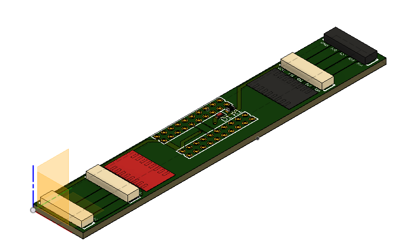
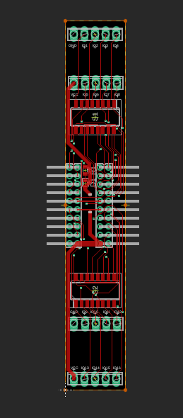
First system that I want to build is Shutter Controller use case
- Define usecase for PoC - DONE
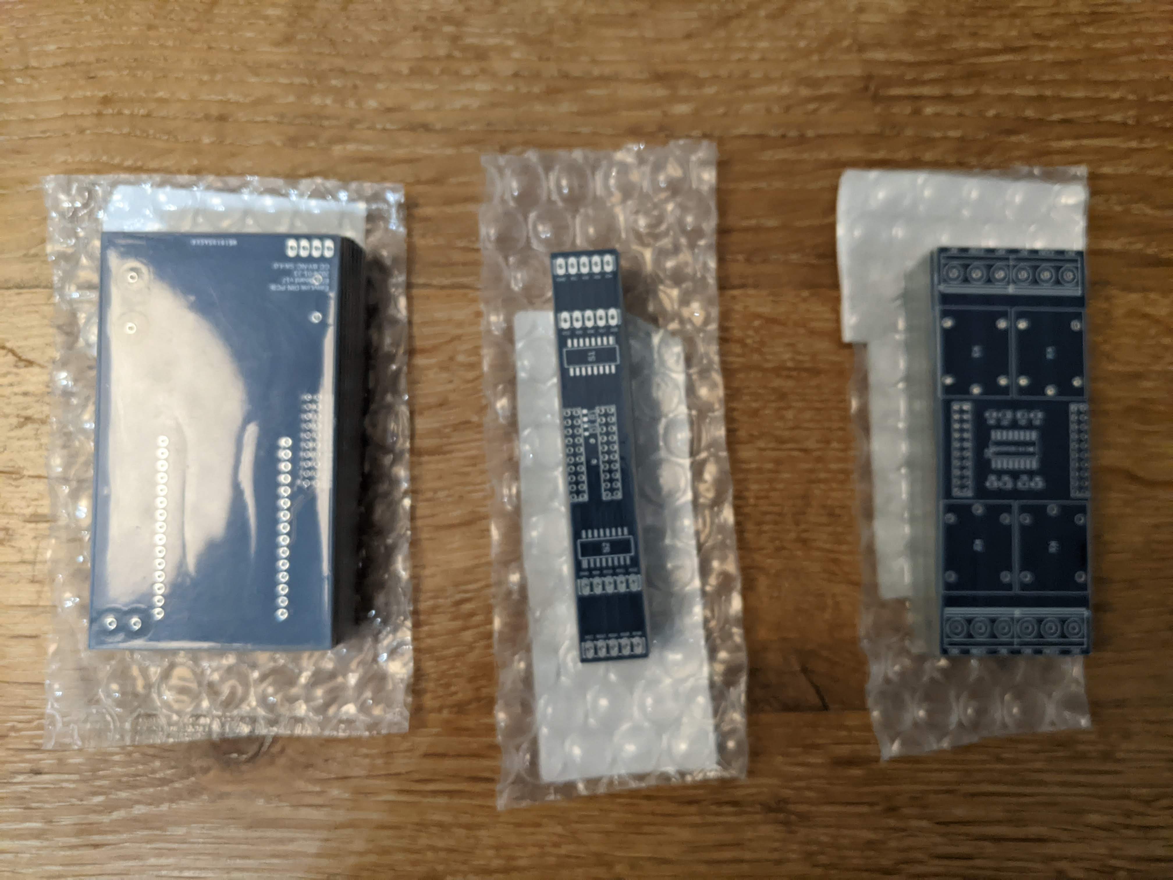
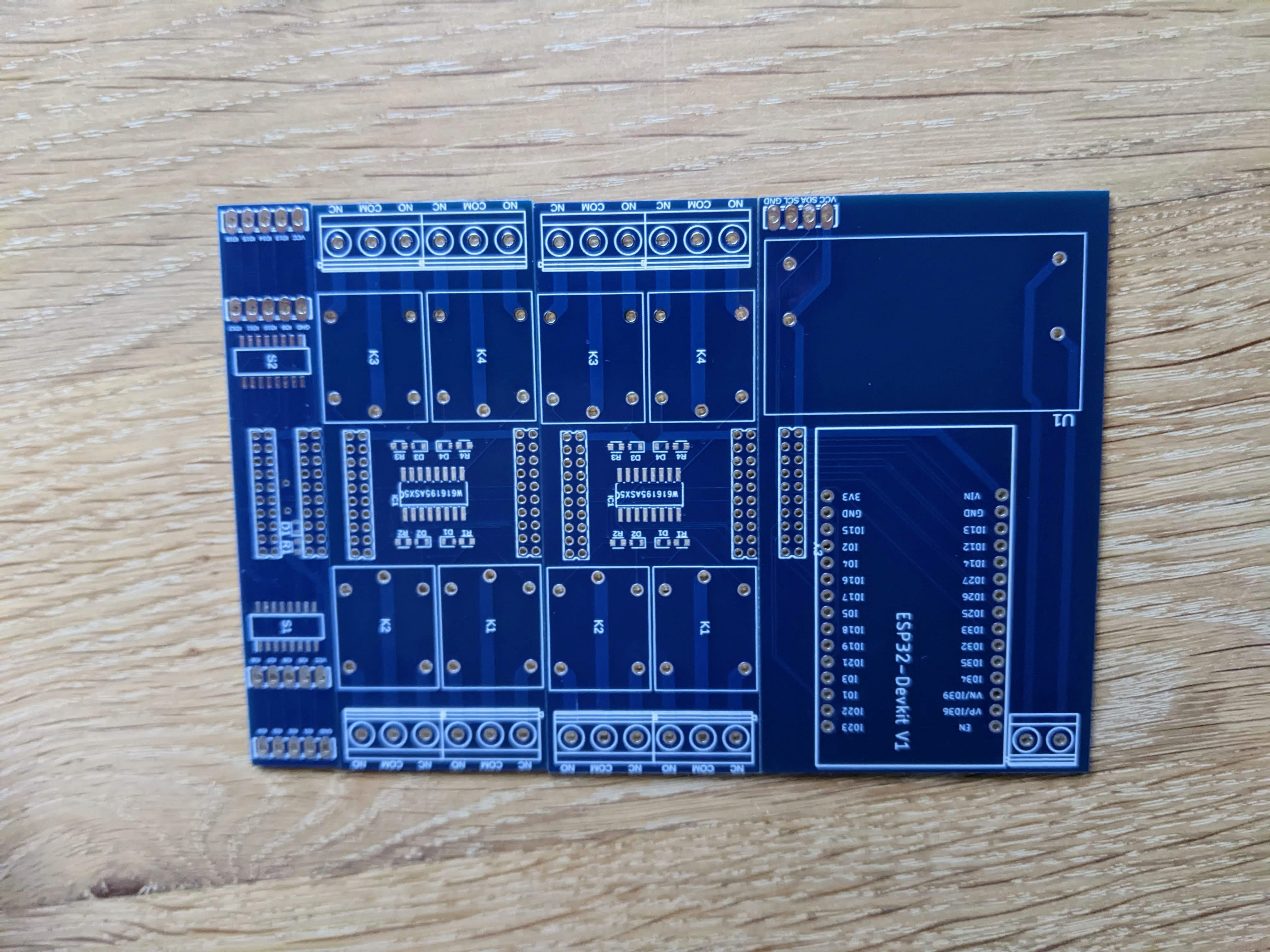
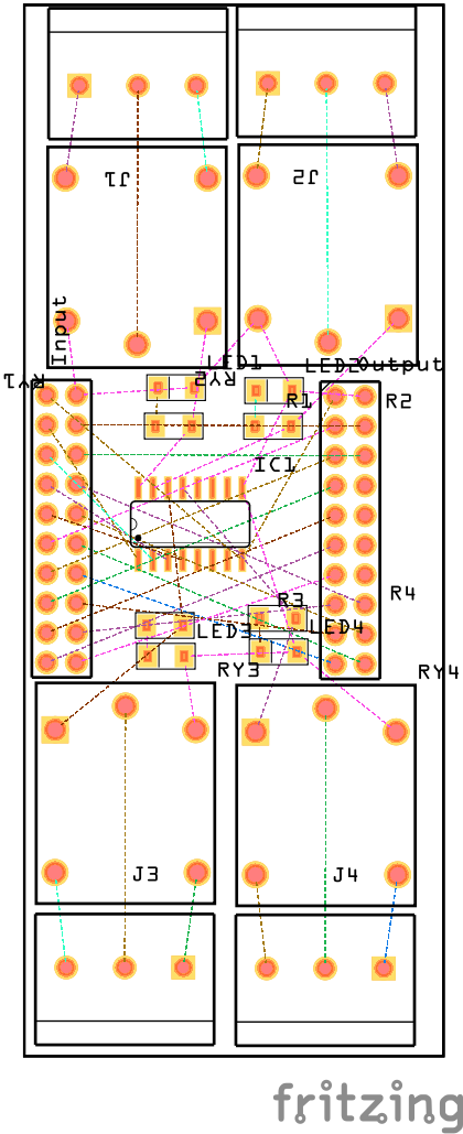
- Design PCB - DONE
- Manufacture PCB - DONE
- Soldering - DONE
- ESPHome installation & testing - DONE
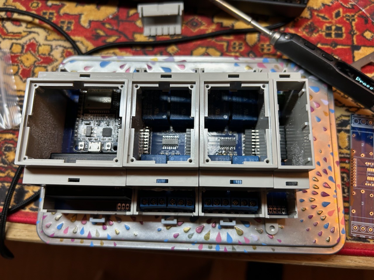
- Packaging into DIN cases - DONE
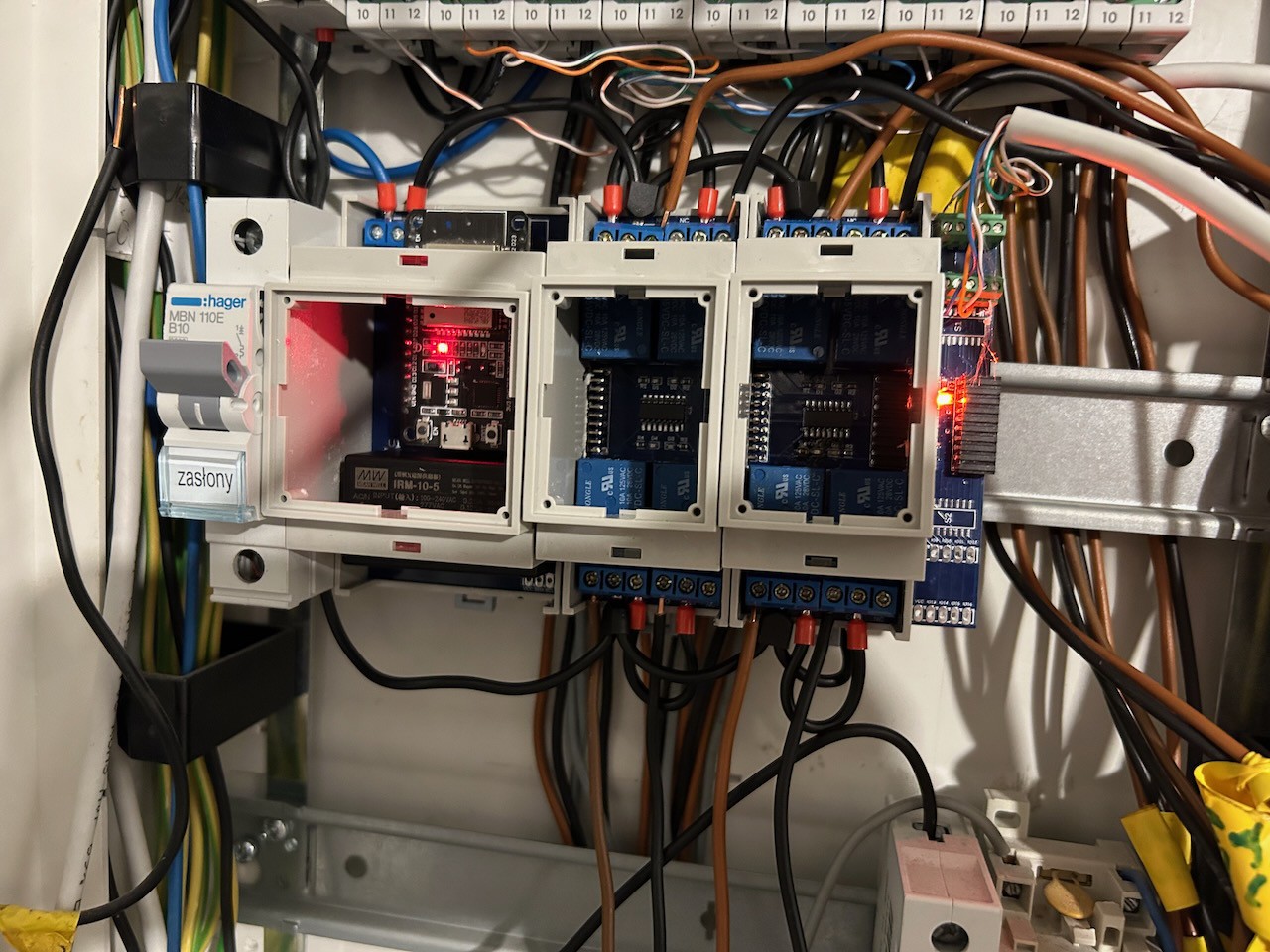
- Installation of prototype - DONE


 Timothy Woo
 Michel Racic
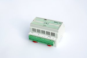
 strange.rand
 VASILIS VORRIAS
You had me at "DIN rail"...