 jaromir.sukuba
Project A
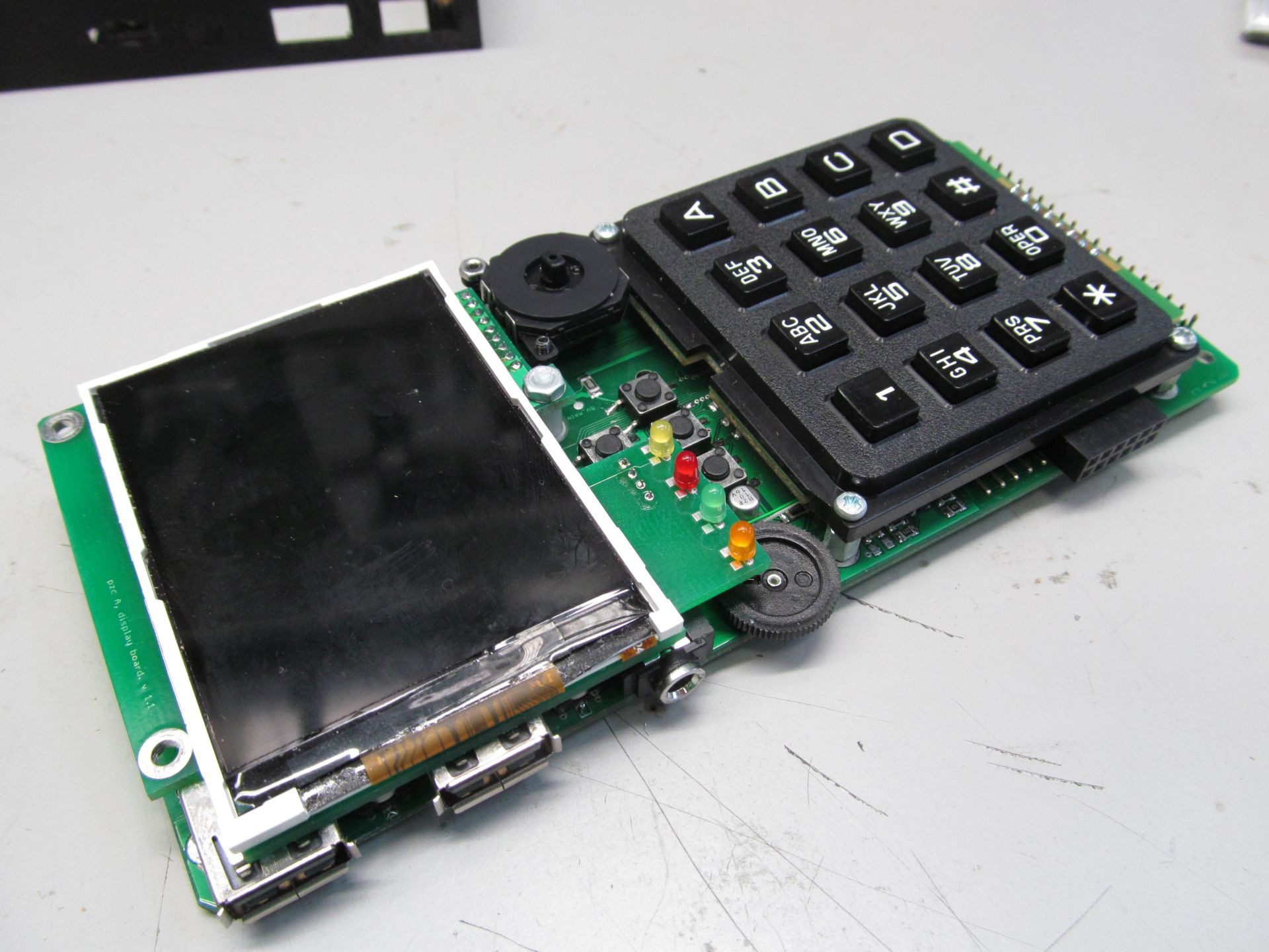
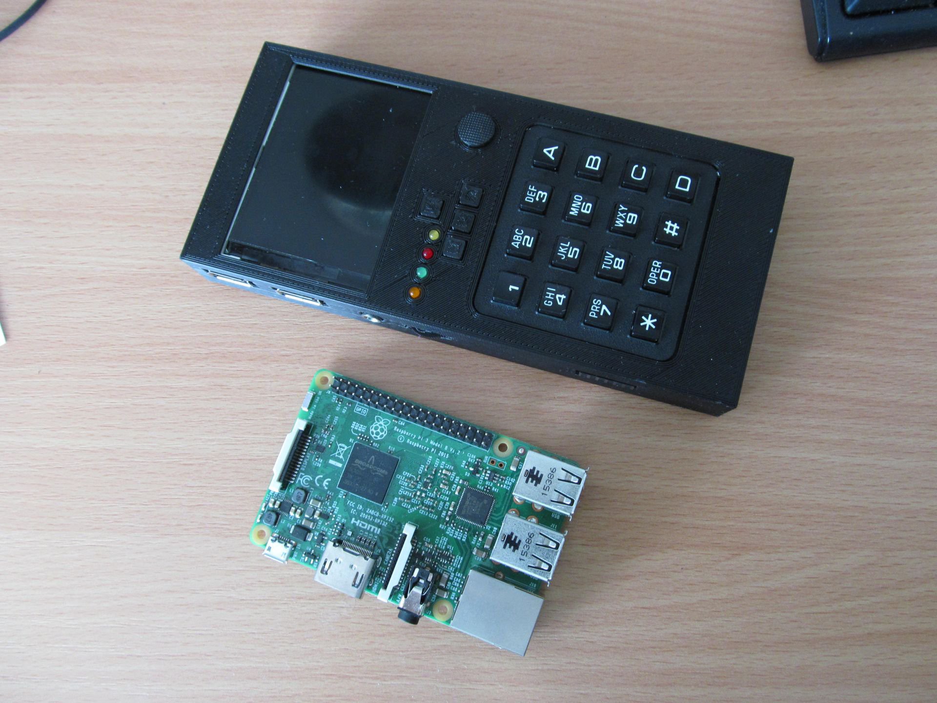
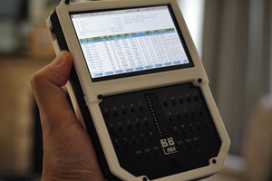
This is computer in brick-like form factor, resembling overgrown calculator.
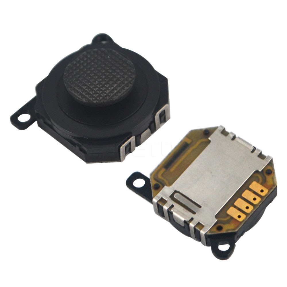
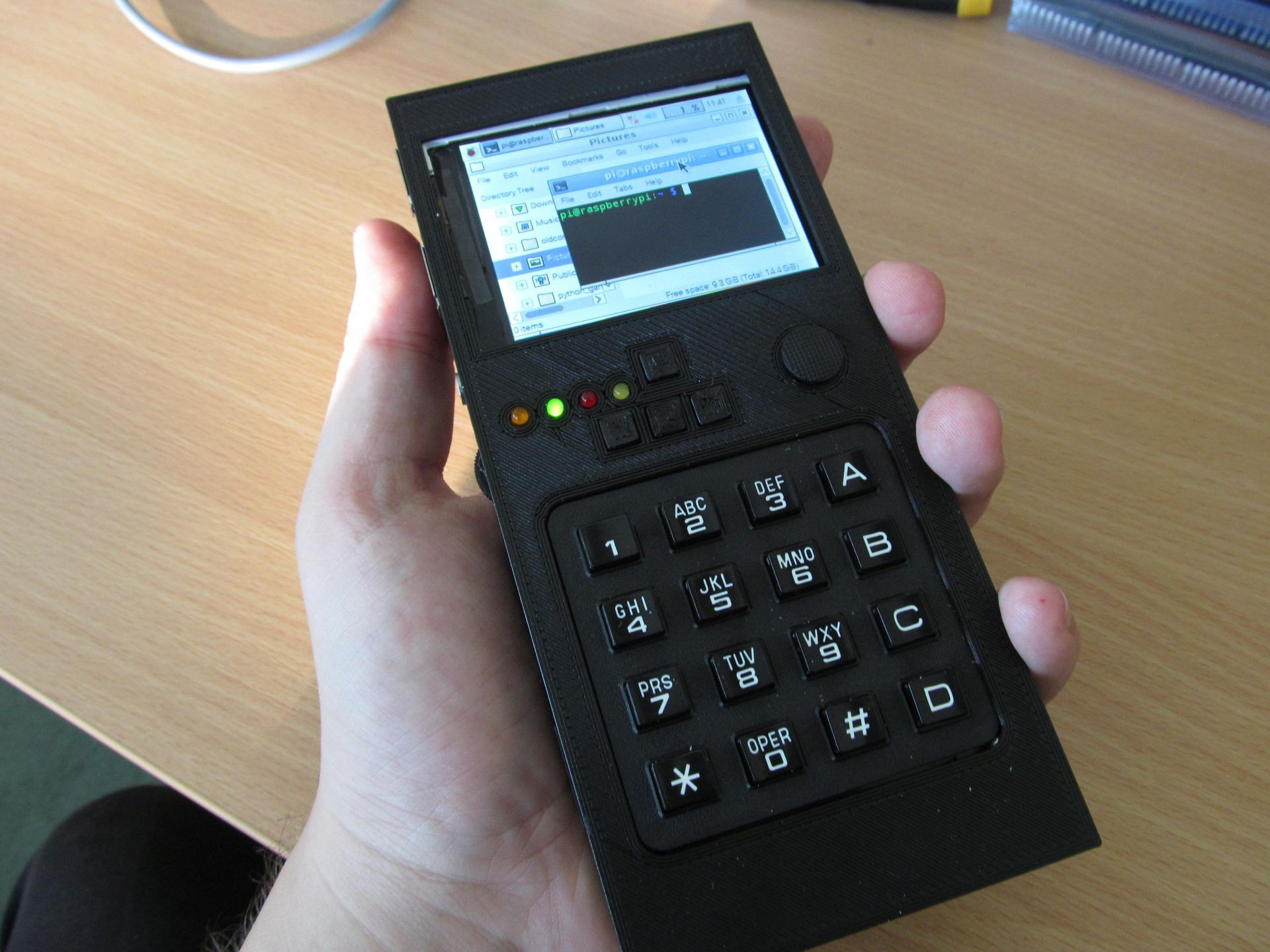 It contains Raspberry Pi Zero inside, plus WiFi module, some power management. It has 320x240 TFT as display, 4x4 keyboard as input device and analog joystick as pointing device. Along with that two full-size USB A connectors, one 3,5mm jack for headphones and 2x6 pni 0,1" header with some PGIO of RPi Zero broken out. The keyboard and "trackpad" interface si very spartan, but it's included all in single enclosure and gives the rudimentary means of controlling the device. External keyboard or mouse is possible to increase user comfort, but not needed.
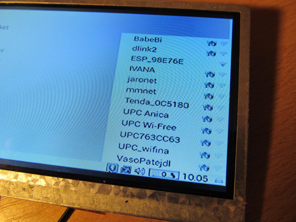
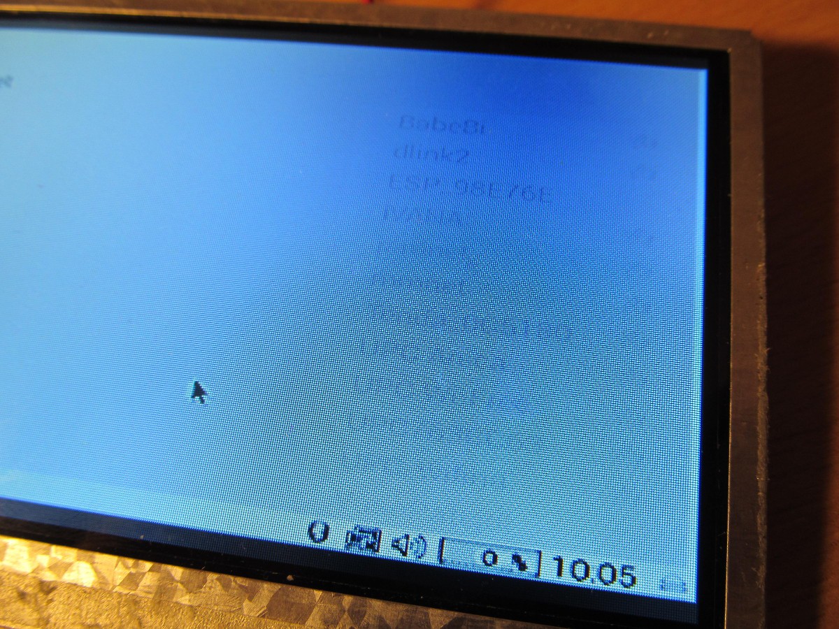
It sports Raspbian Linux, with all the software you can run in 320x240 display.
Project B
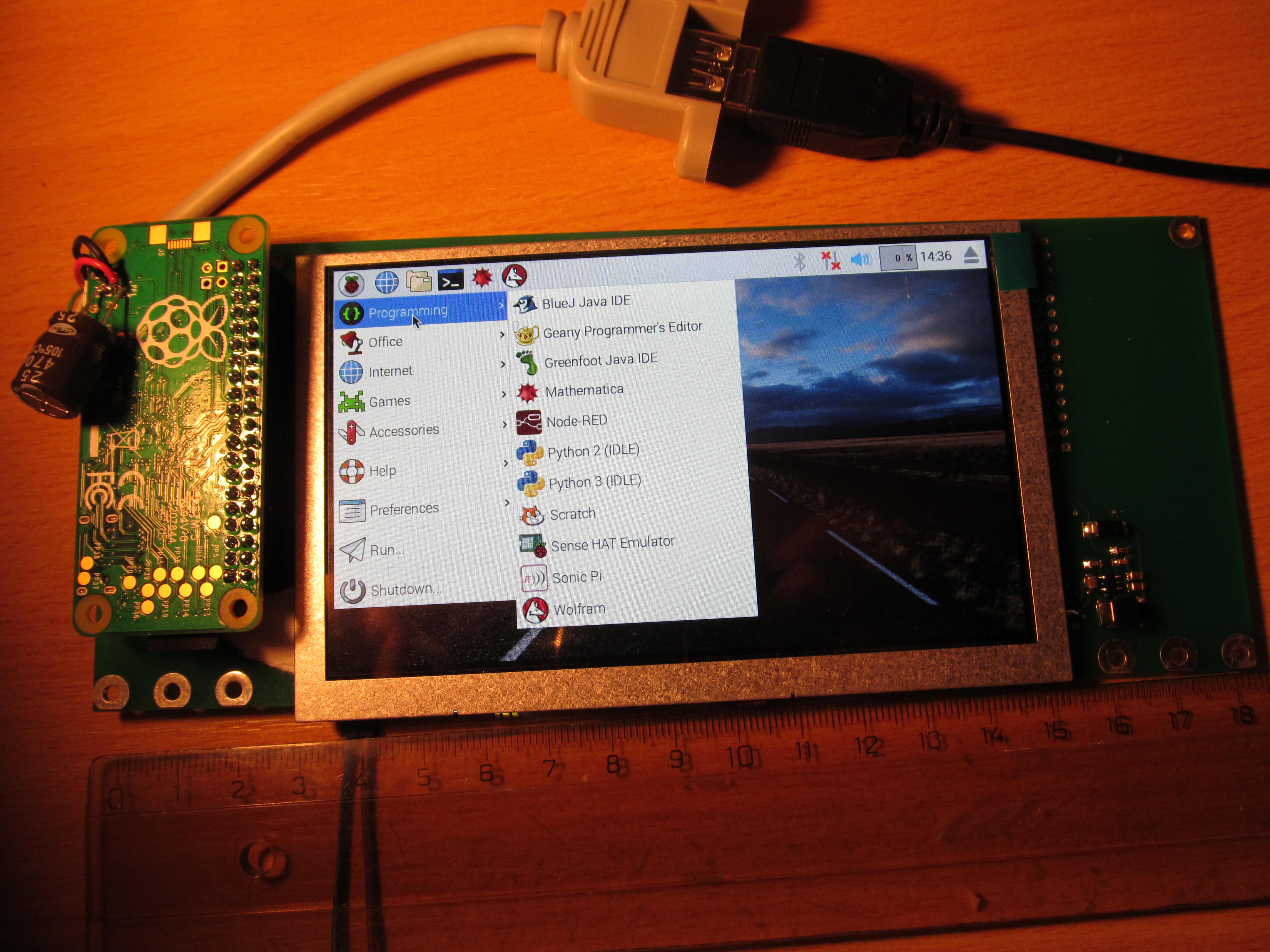
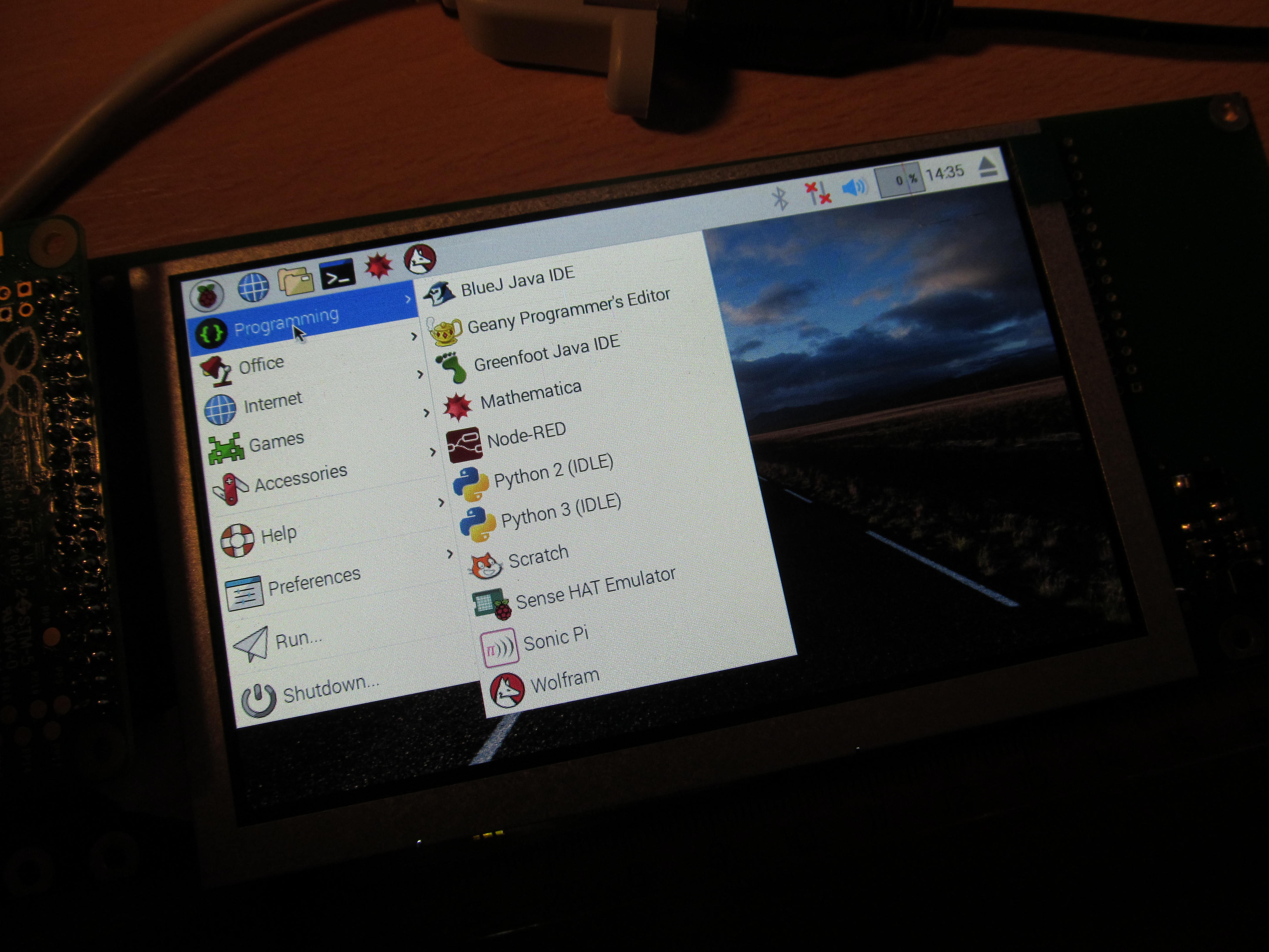
This is still under development. It will have larger display and qwerty keyboard.
FAQ:
Q: How is this better than my phone/tablet/smart toaster?
A: If you need to ask this question, then it isn't any better.
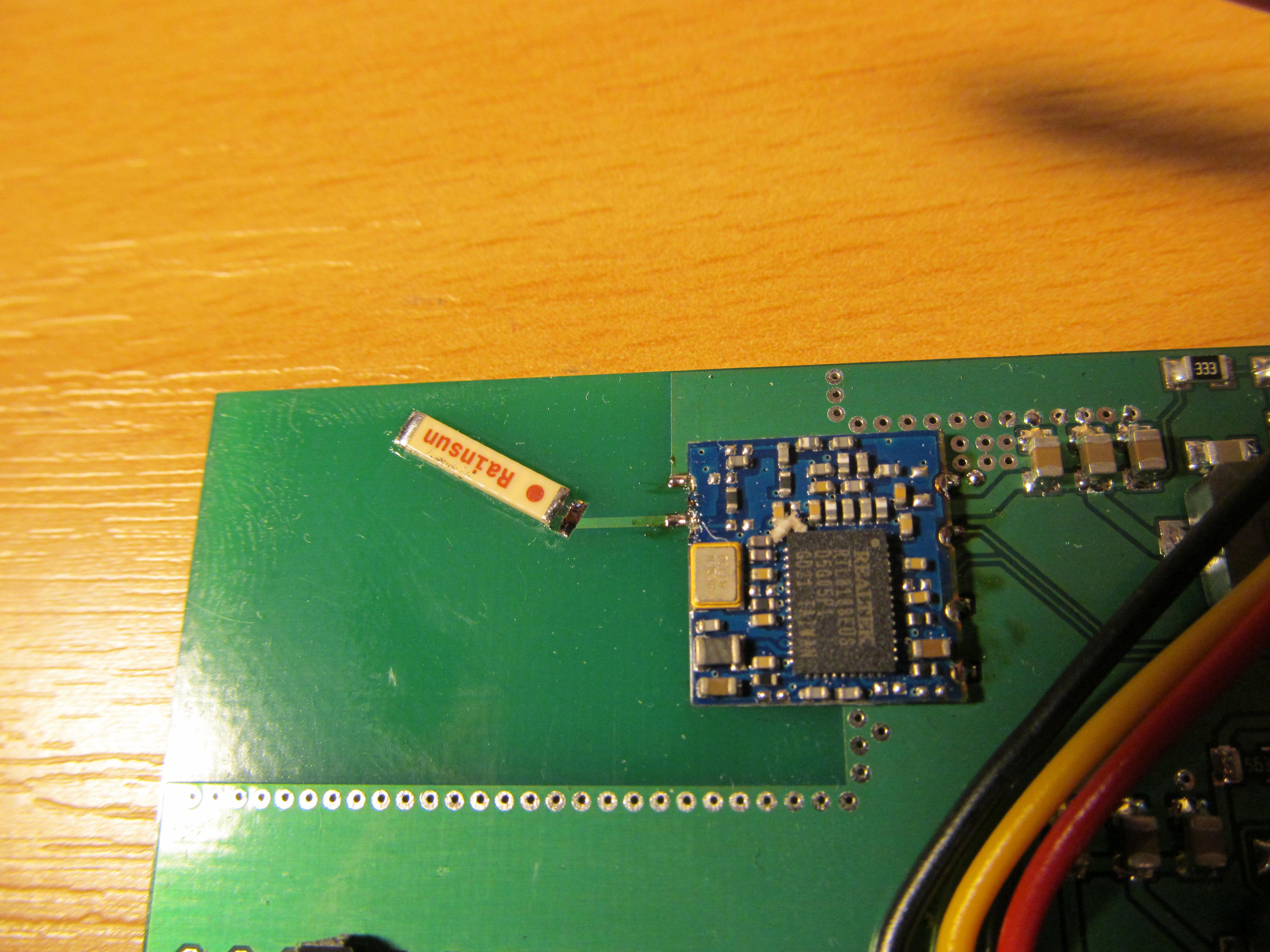
 There is really nothing but single resistor on bottom side
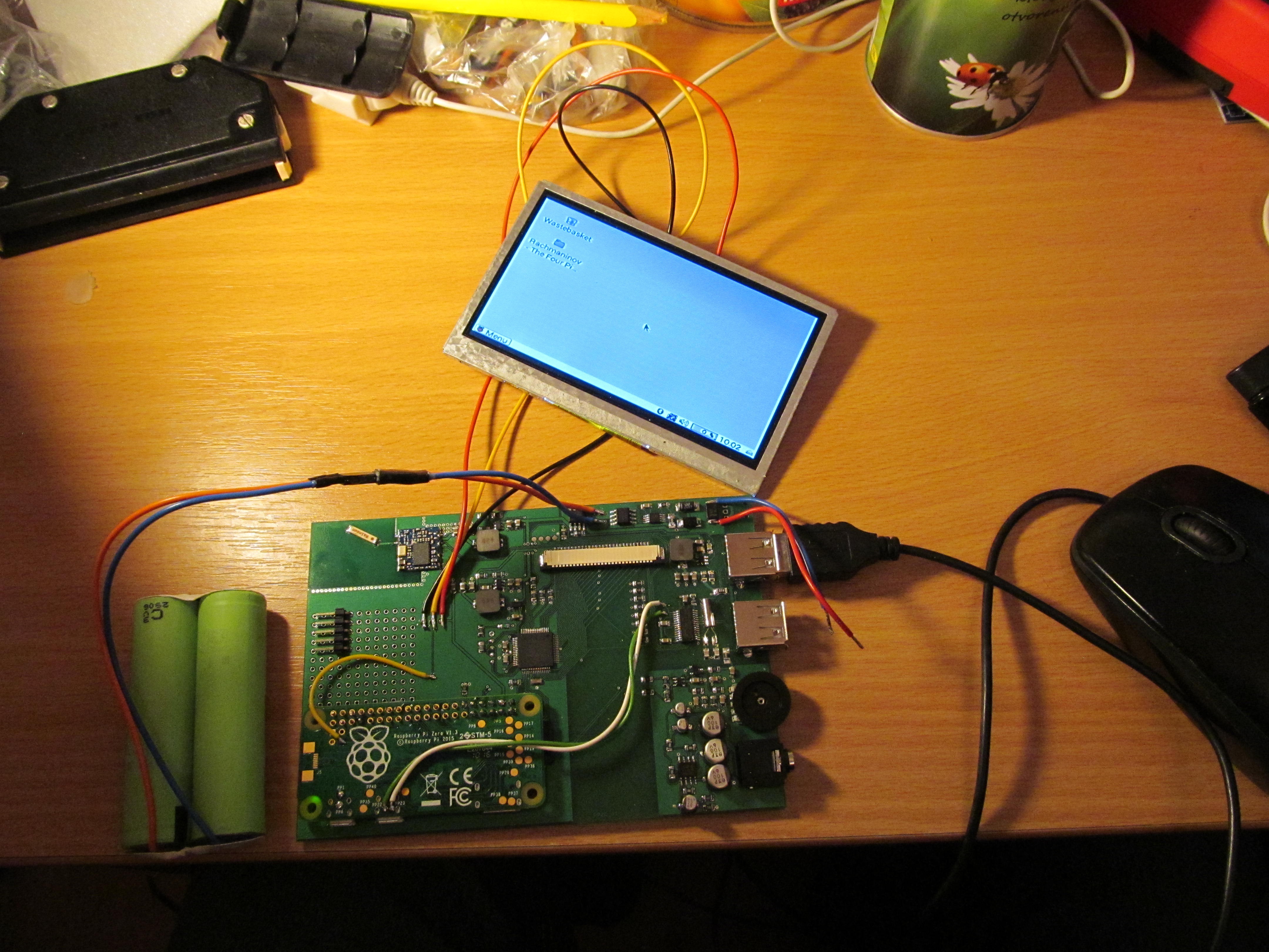
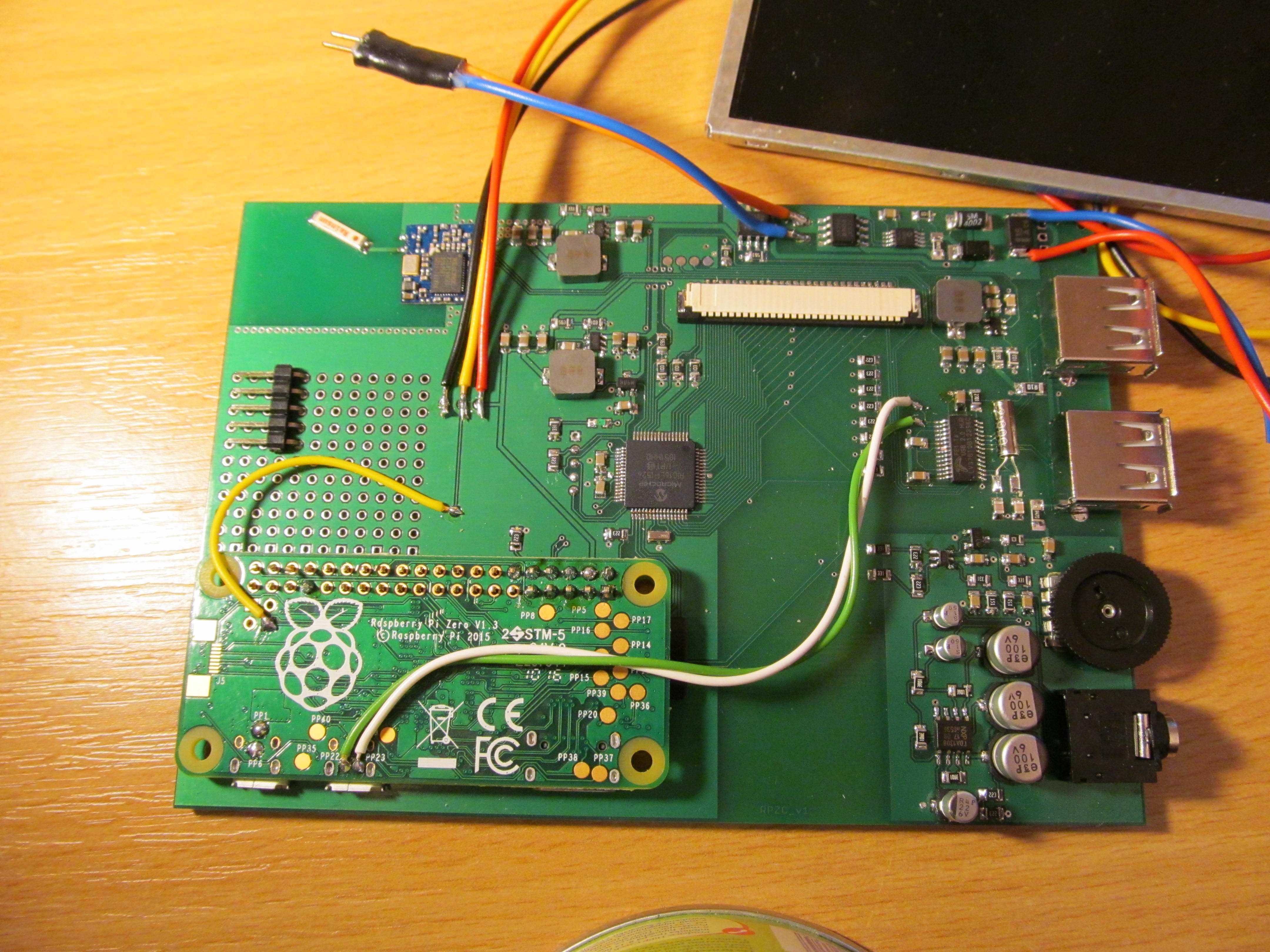
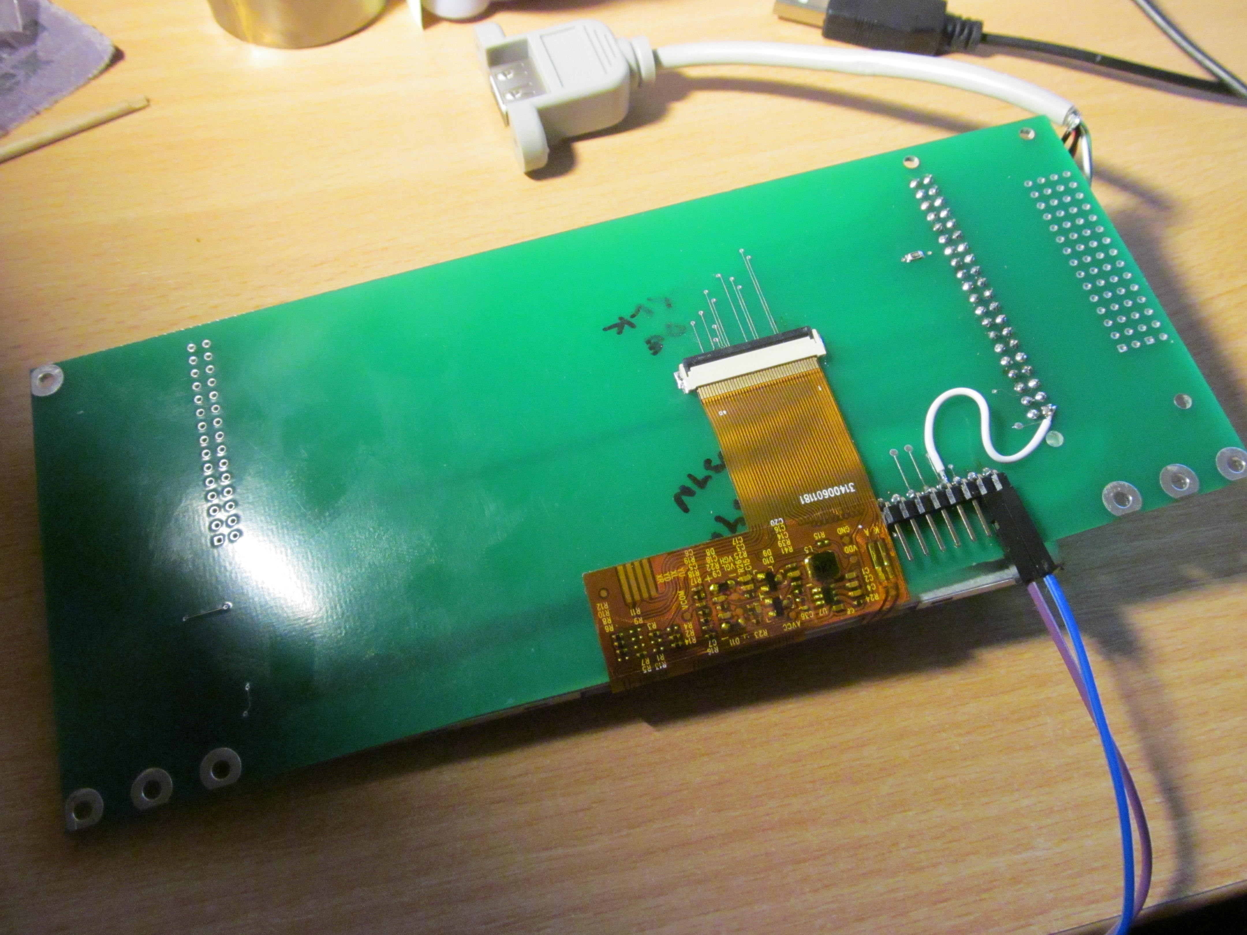 The whole setup takes approximately 1,5 Watts during run. It could be lower, but this is still manageable
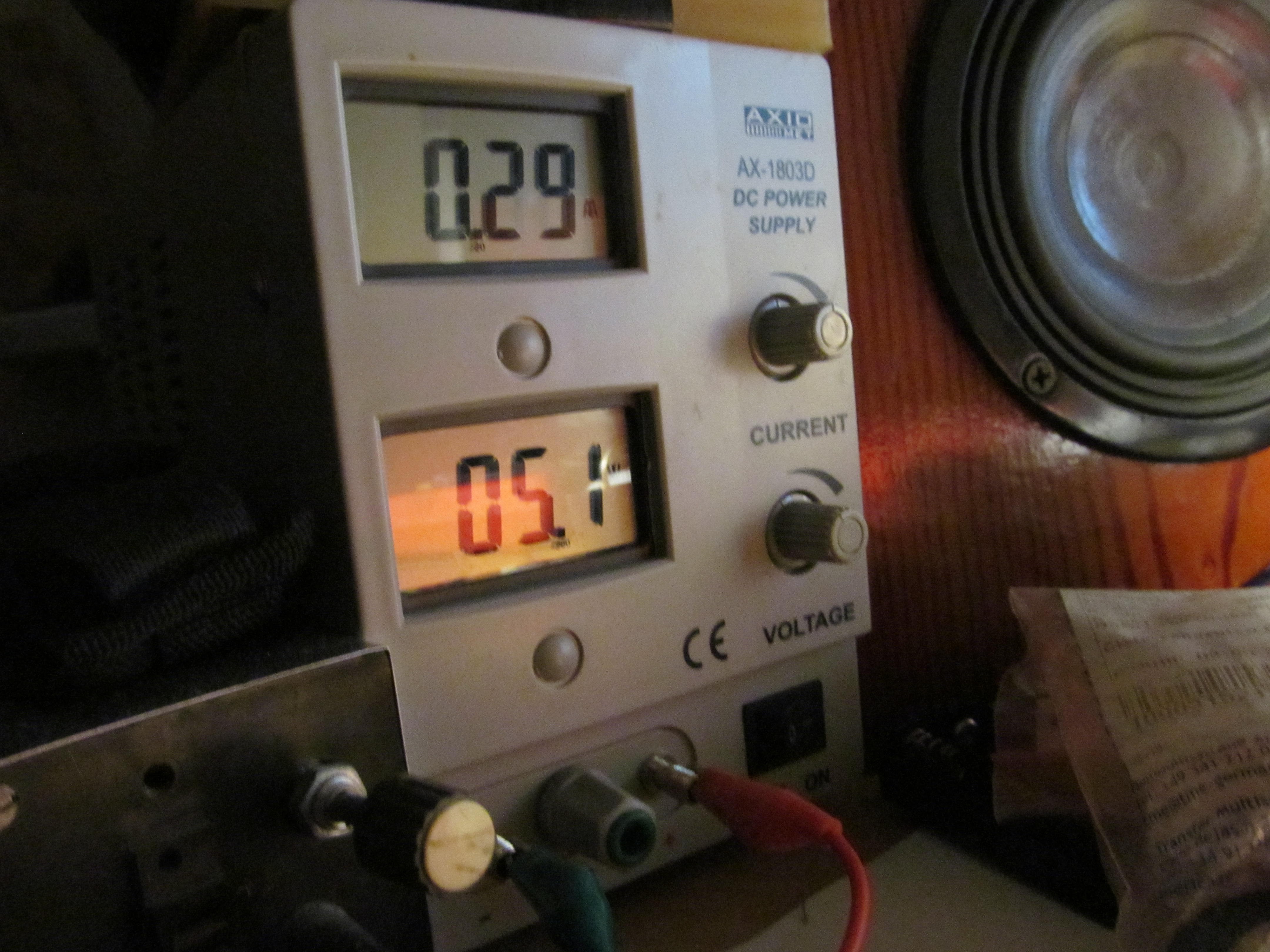 Now I'm in the process of adding keyboard and pointing device to this - not the joystick I had on project A, but touchpad. This is going to be non trivial process, as most of the GPIO pins are taken by DPI interface and this time I don't want to run everything from internal USB. Stay tuned.
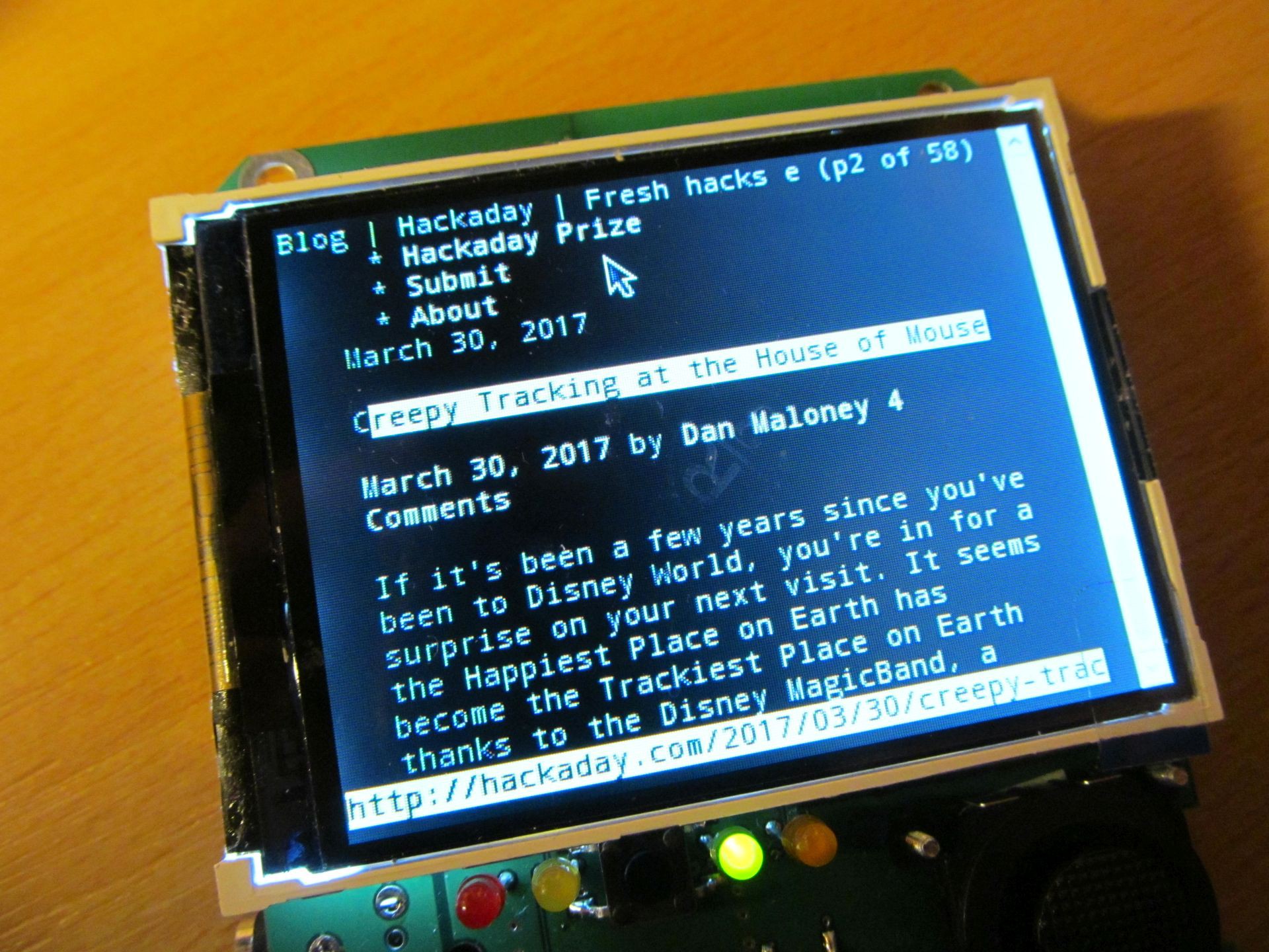 Chromium works here too, but due to small display it isn't very enjoyable to use.
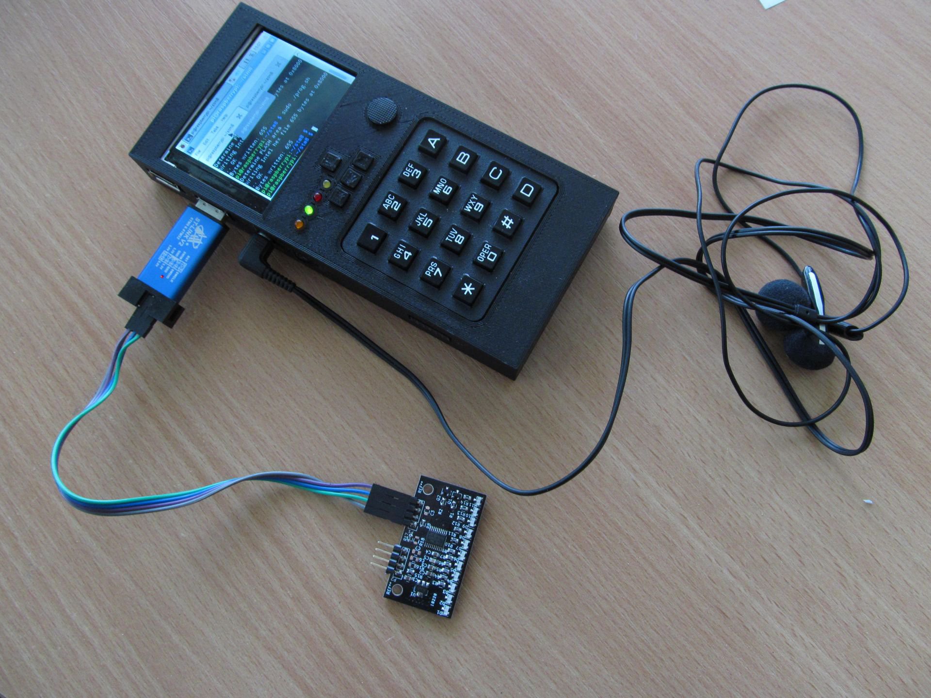 or on arduino platform
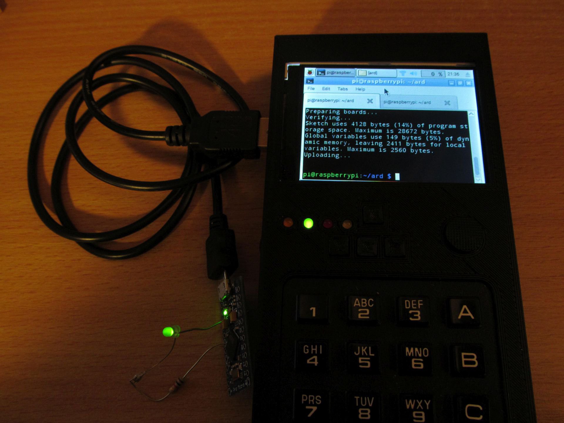 I believe STM32 targets should work too, as well as PIC devices, using
 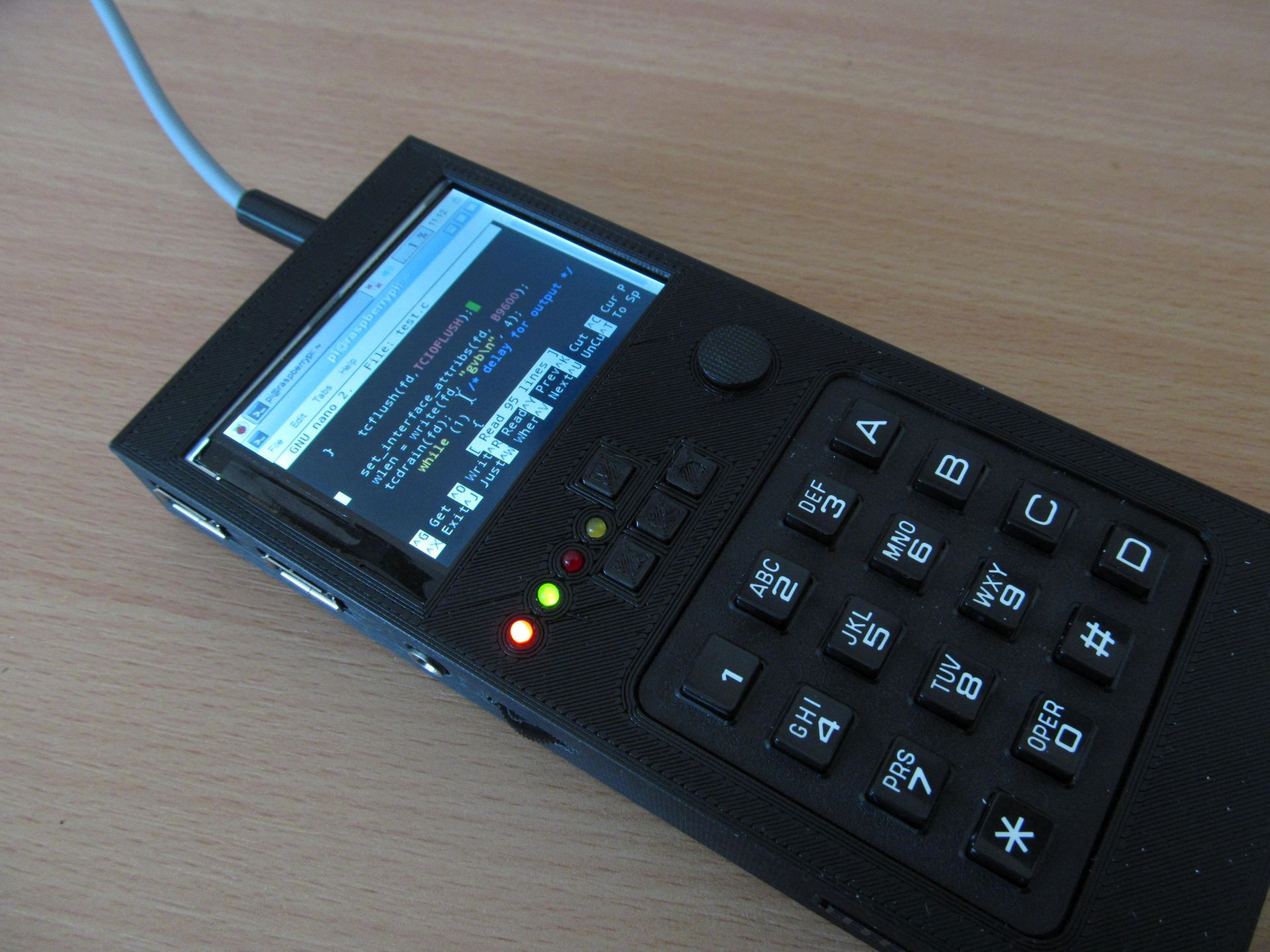 Oh and don't forget to backups. Here is my take on SD card backup system.
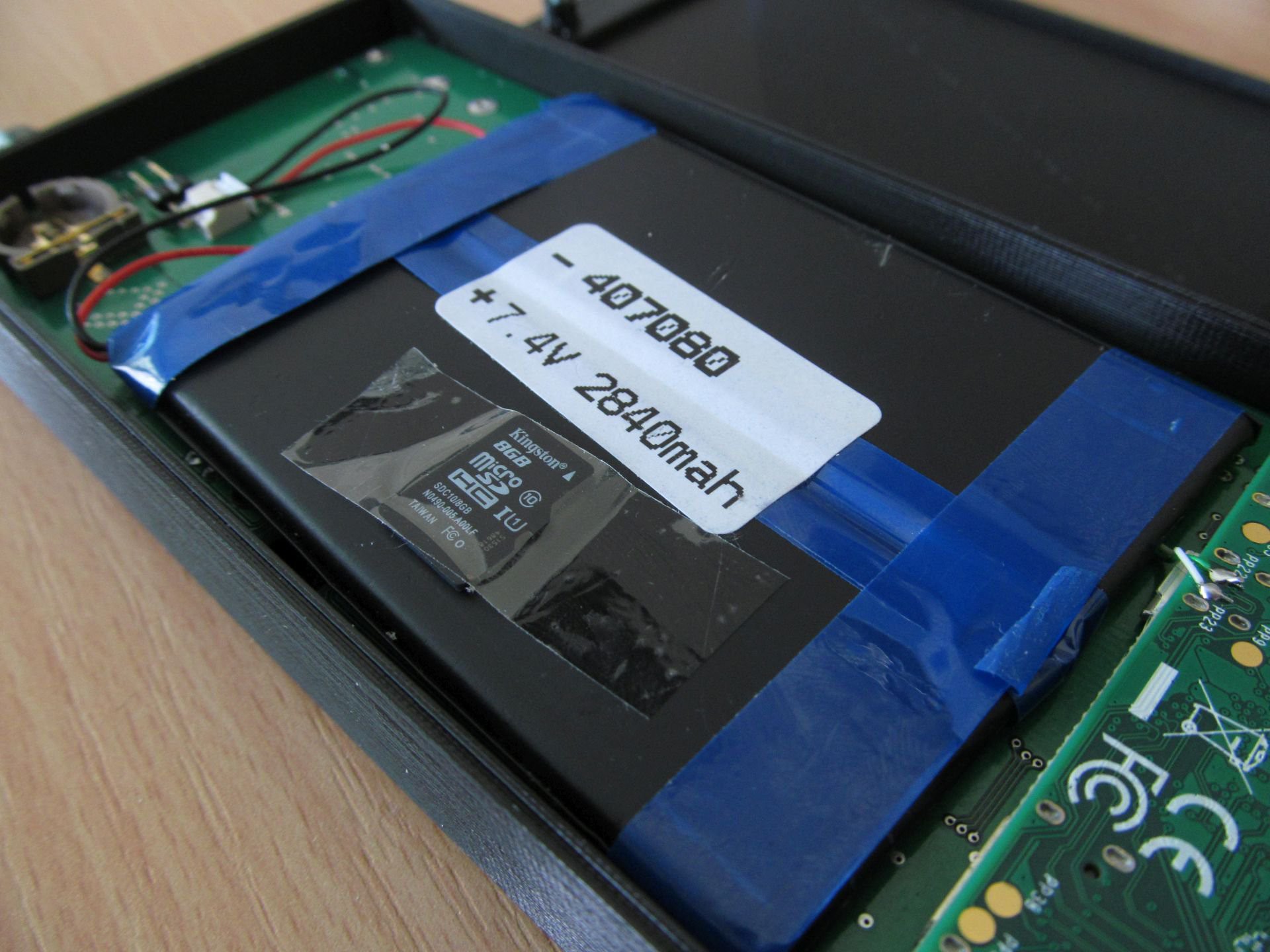
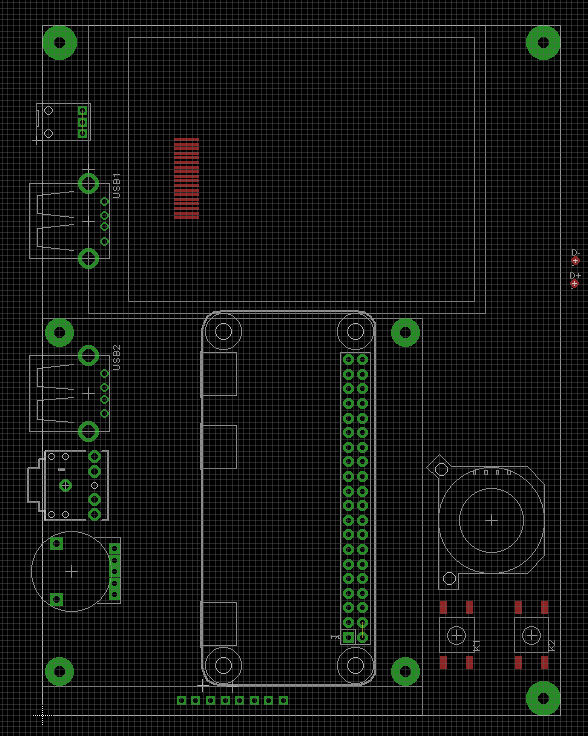
 In the meantime, I made some minor changes to circuit, but the overall concept was still the same. Complete schematics is here
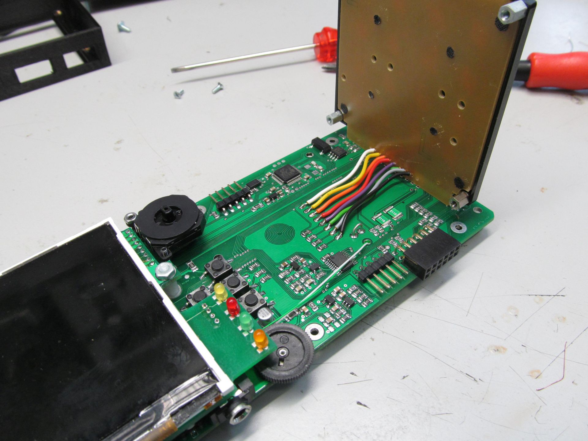
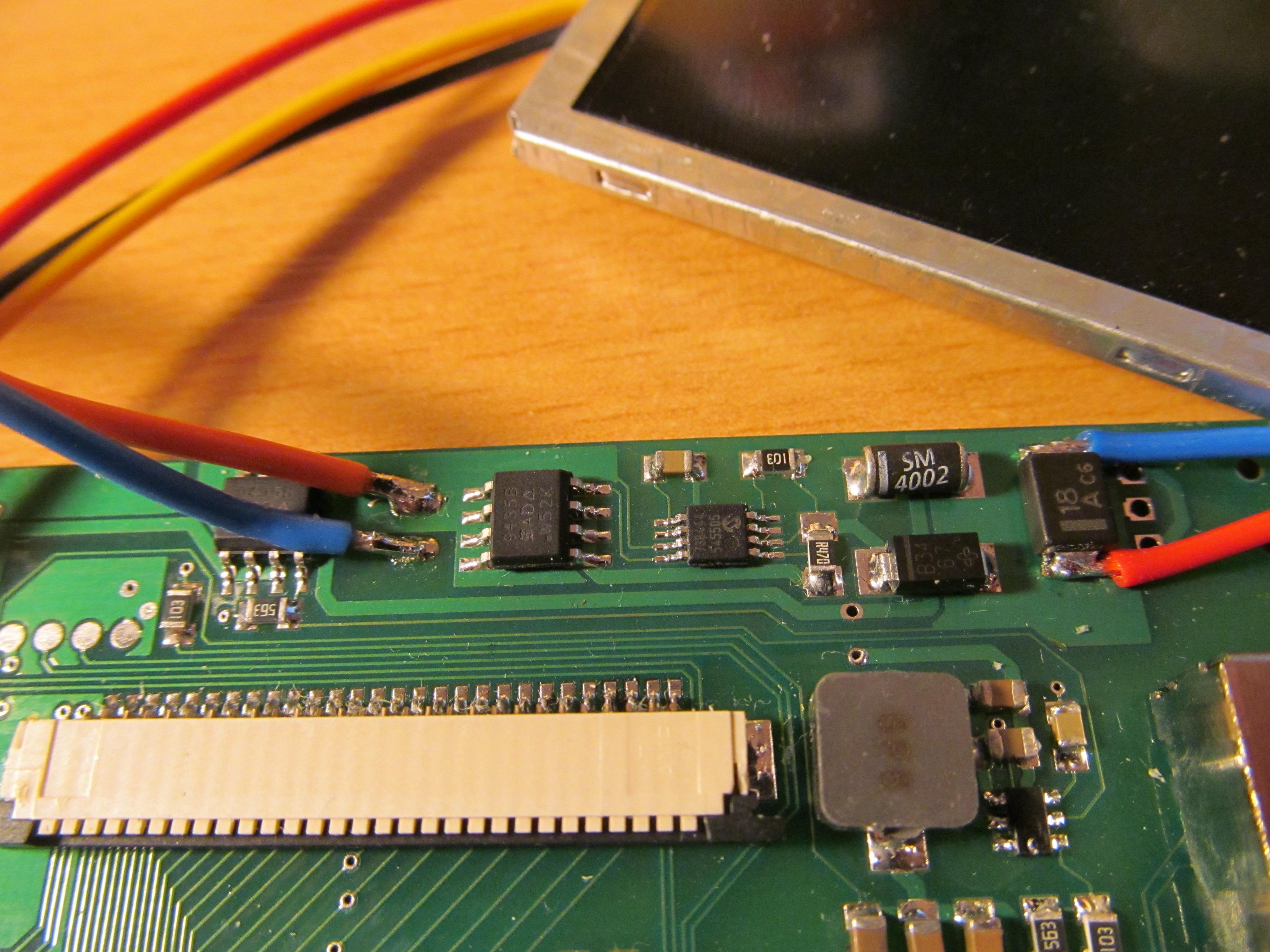
 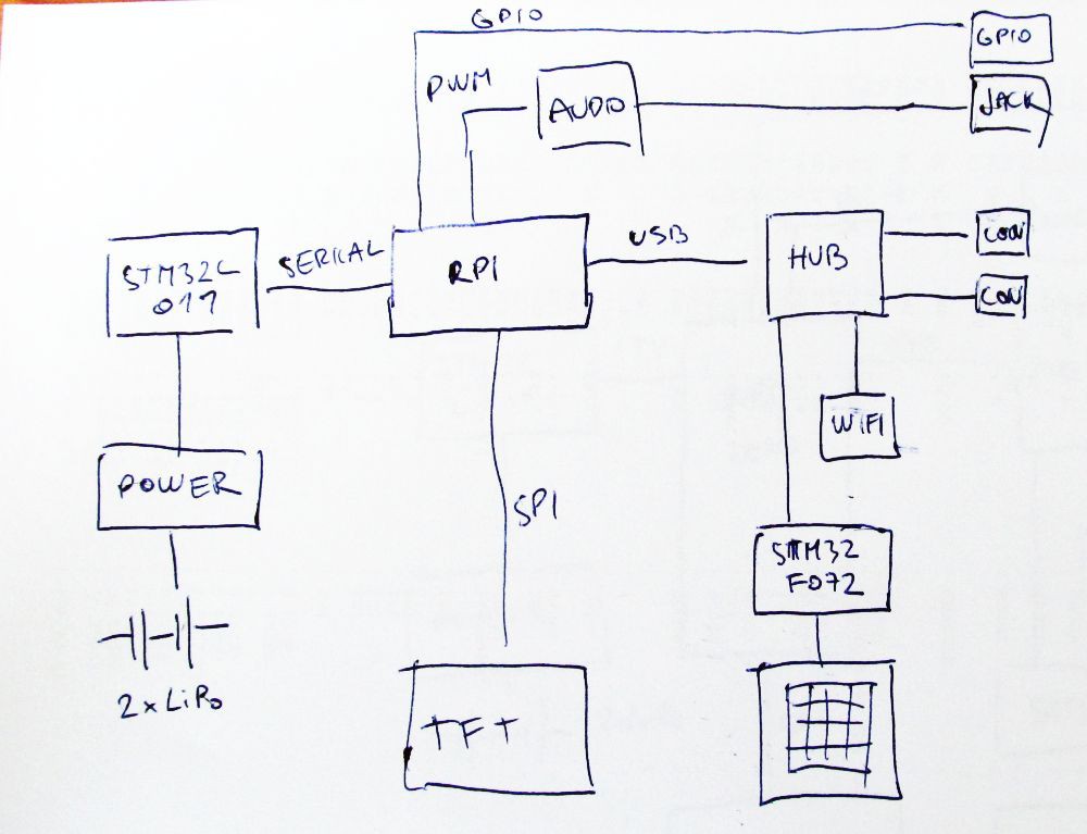 Heart of the device is Raspberry Pi Zero. The power is delivered from two LiPo cells in series, MCP73844 acting as charging IC and three TPS562200 are performing DC/DC down conversion to get three voltages:
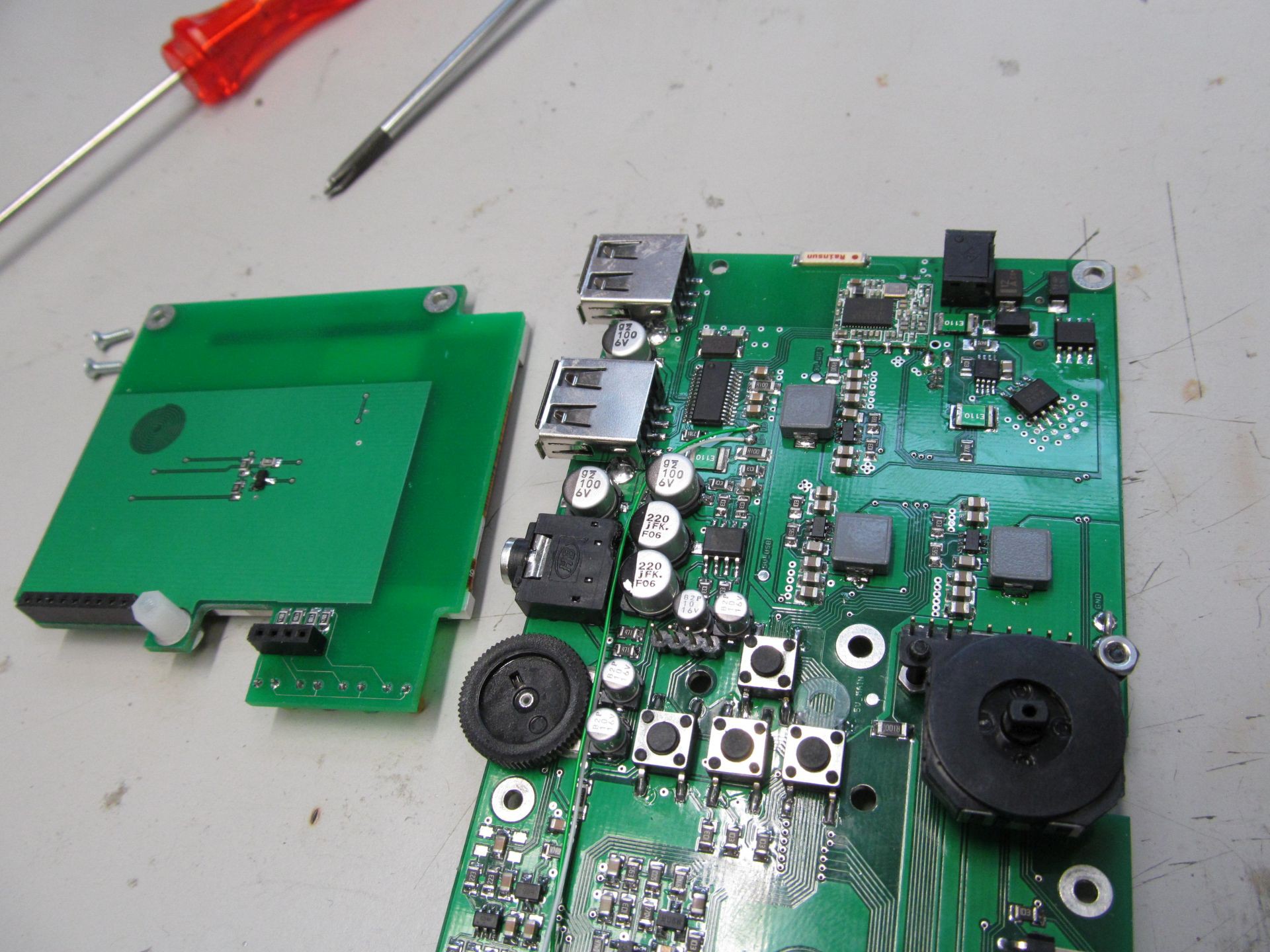
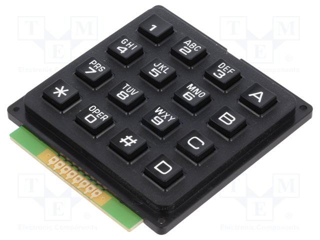
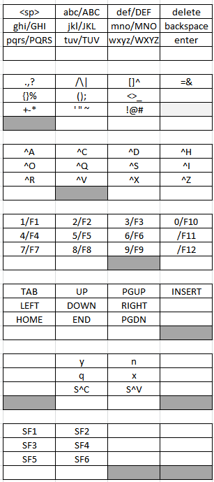 Gray keys denote pressed modifier keys. With no modifier keys pressed, you have to top layout - press key 7 once, you get 'p', press one more within 800ms, you get 'q', then 'r', then 's'. For special characters, press first modifier keys. I tried to arrange them in some logical manner, grouping related characters, like parenthesis or +-* symbols. For running executables in bash, press left modifier, hit first and second button, this types ./, then name of executable (using tab key saves you some typing). Forethink the executable filenames at least a bit and you can run most of them in a few key hits.
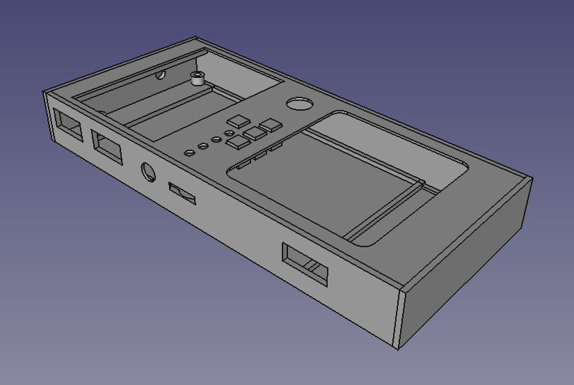 Threaded inserts are used to keep everything in place and to allow repeated teardown of the case, so much needed when tinkering with the device. Self tapered screws would be easier, but not as reliable choice here.
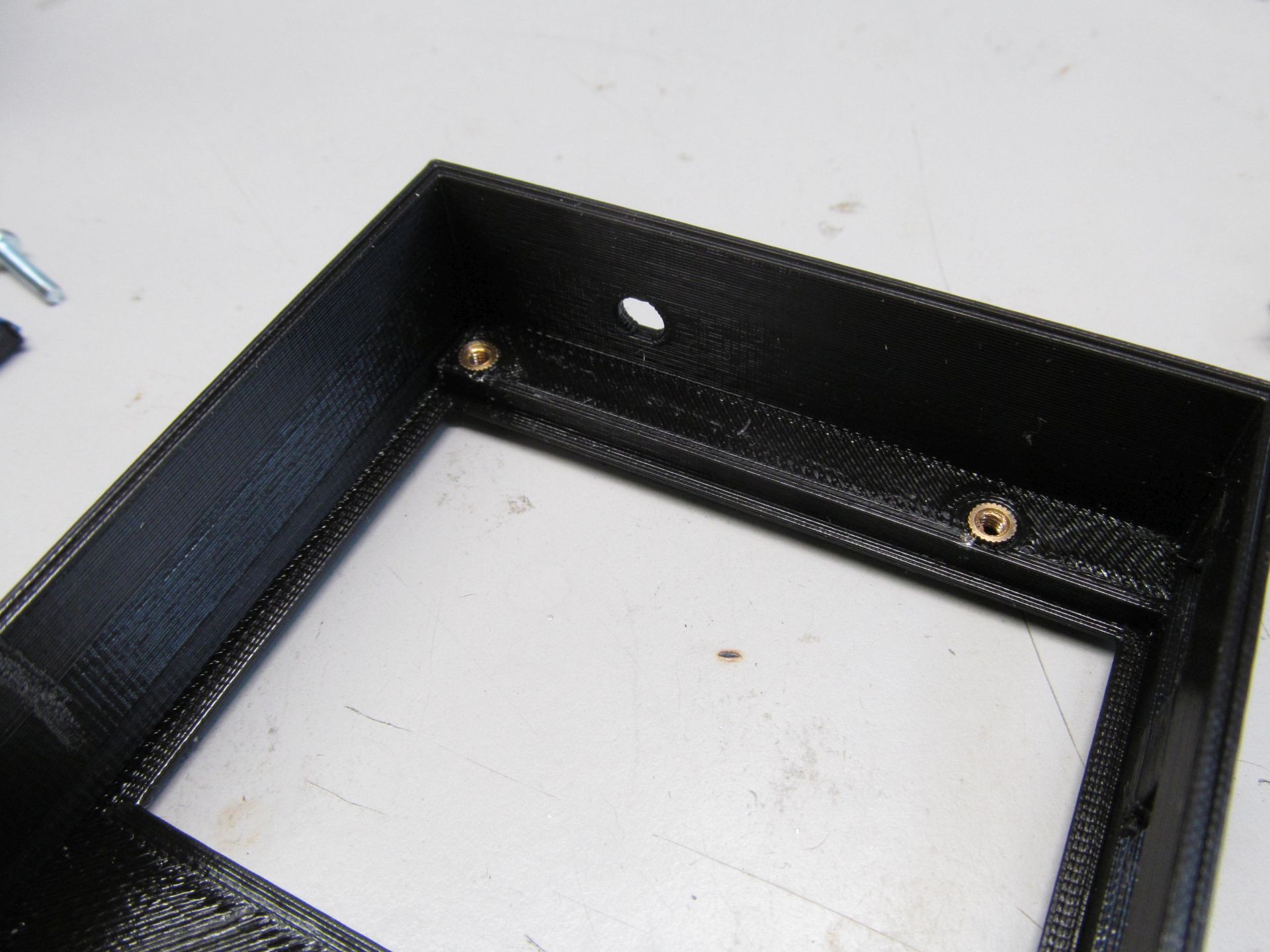


 Richard
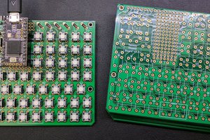
 Anthony DiGirolamo
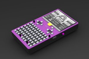
 pcadic
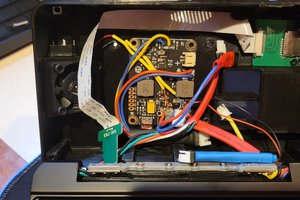
Is this being sold anywhere?