Valdez
Where it all started:
In late 2023, Chamberlain started blocking the MyQ garage door integration from Home Assistant. This move confirmed my concerns about relying on integrations that communicate through cloud based APIs. I begrudgingly overcame MyQ's blockade by soldering smart relays to the pushbuttons of a wired garage door opener and using contact sensors to receive the position status. However, MyQ left a sour taste in my mouth, and since I was also running the alarmdotcom HACS integration for my DSC Neo panel - an integration that warns it "communicates with Alarm.com over an unofficial channel that can be broken or shut down at any time" - I was determined to find a way to integrate my encrypted DSC Neo panel locally so that it would not become the next MyQ.
Neo's encrypted bus blocks any direct integration from non-partners, but I learned from the MyQ blockade that if you can interact with a device physically, i.e. by reading a simple lcd screen and pushing some buttons, no matter how strong the encryption is between that device and its mothership, the information to and from your eyes and fingers must be in an unencrypted form that can then be intercepted or injected remotely. I focused on the keypads, and on building an ESP32 based virtual keypad integration that would sniff the Neo Keypad's lcd screen data bus and hijack the keypad's button matrix. I first documented my journey on home-assistant.io's forum, and now decided to document it here as I continue to refine this project.
Part 1 - Sniffing the LCD Databus:
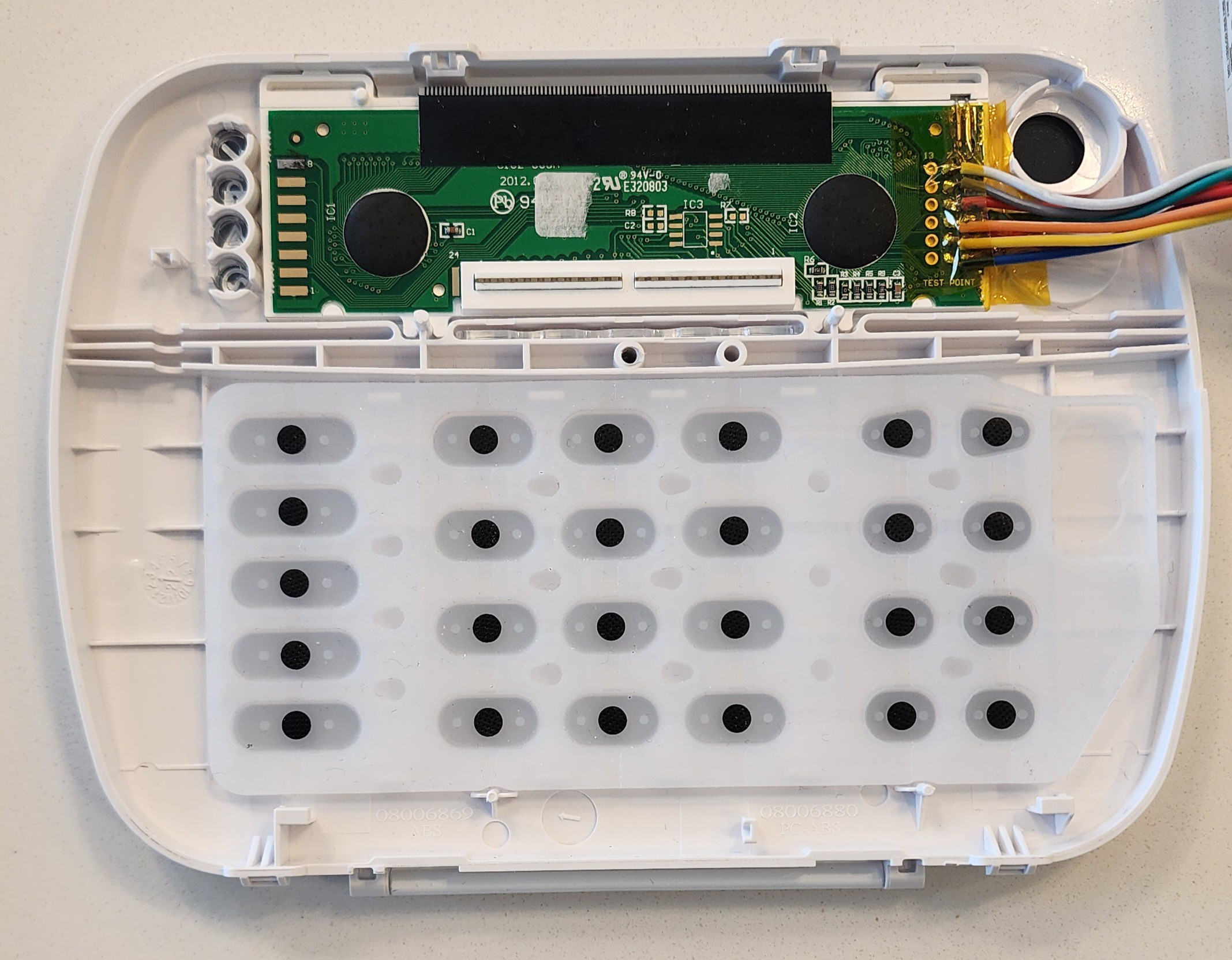
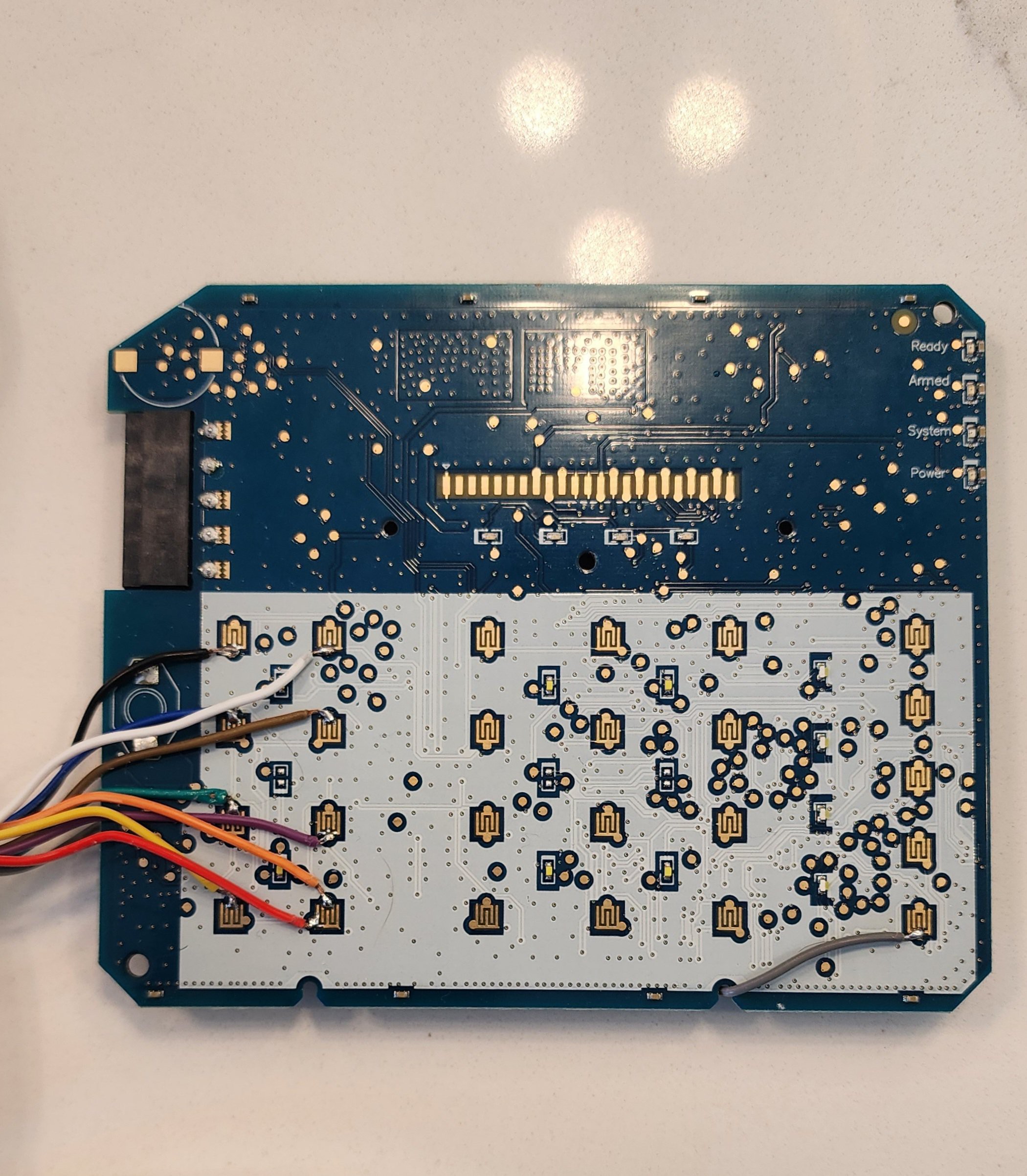
I knew the H2SLCD Full Message Keypad contained a 16x2 lcd display. I suspected it contained the ubiquitous HD44780 LCD Controller. On opening the keypad I discovered the lcd was on its own pcb which connects to the mainboard with an spongy flexible connector that when examined with a magnifier essentially contains a large number of parallel wires or plates sandwiched between two soft pads that connect the contacts on the mainboard to the lcd when they are pressed together.
I first mapped the contacts on the mainboard to the contacts on the lcd by simply looking where the two boards lined up across the connector. Then with my multimeter I started probing to find what I could. I was able to find a number of Gnd contacts, a +12V contact, a +3.3V contact, and a number of contacts reading varying + voltages between 0-3V. I then turned to the various test points on the lcd pcb. I determined that 6 of the test points connected to an unused footprint labeled "IC3", leaving 12 contacts actively communicating with the mainboard. Of the 12 remaining test points, the first that were easily identified were the cathode/anode of the LCD backlight (labeled K/A at the top right of the board), Gnd, and +3.3V. That left 8 test points unknown. If I was dealing with an HD44780 LCD controller, it would have to be working in 4 bit mode, with the remaining 8 contacts likely being Vo (contrast control), RS (Register Select), RW (Read/Write), E (Enable), and D4, D5, D6, D7 (4 data lines).
I ordered a 20$ USB logic analyzer off Amazon and started analyzing the signals. I used Logic 2's built in HD44780 analyzer and attempted to identify which signal might be which. I had a good idea which signals were likely RW, RS, and E based on the datasheet, but I was not sure the order of the 4 possible data lines. There could be 24 different combinations in the order of the 4 data lines, and through trial of error, I ran through all the combinations (I went through the 24 combinations a few times only to discover they were in the correct order on the pcb to begin with) and while changing various settings in the analyzer settings, eventually "\x80System Is \xC0Ready to Arm" appeared across the top of the E line! I had successfully decoded the LCD controller and was reading the keypads status with my logic analyzer.
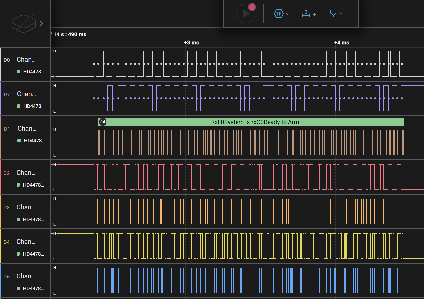
RW = white, RS = purple, E = brown, DB4-7 = red/orange/yellow/blue. The \x80 and \xC0 codes are likely internal register instructions (i.e. to clear the screen and drop to the next line) as the internal register instructions happen when RS (purple) line is low which is when that data is sent. When the RS (purple) is low and R/W (white) is high, the keypad is reading the busy flag to ensure it is safe to write. When RS (purple) is high and R/W (white) is low the keypad is writing data to the LCD controller which is the data we want to capture. The pulsing of the E line times the reading of DB4-7 and the controller reads 4 bits at a time, combining pairs of 4 bit bytes together to build an 8 bit character that will be printed to the LCD screen.
With the HD44780 connections identified, it was time to wire it up to my ESP32 and attempt to decode the data in software.
I modified the HD44780 decoder code written by Leonardo Martins, and I was able to get the Keypad's LCD displaying in the serial output in Arduino IDE from my ESP32.

How the code works is an interrupt is triggered when the E line goes high. It then reads the 4 bit parallel data if RS is high and RW is low (signifying the keypad is writing data to LCD). Every second read is added to the previous to build an 8 bit byte encoding the character and is then stored in a character array containing the lcd message. When the entire 16x2 = 32 character message has been stored, the message is sent to Home Assistant by publishing the stored string to an MQTT topic where a sensor in Home Assistant is programmed to listen to and take on the state of the MQTT topic. I now had the keypad LCD displaying in Home Assistant and updating with each change. Now all I needed to do was push the keypad buttons virtually.
Part 2 - Hijacking the Keypad Button Matrix
I started by probing the 25 keypad button contact pads.
I found that each button contact had a side tied high and a side that was low. Using my multimeter I found that the contacts were joined together in sets of 5 buttons on both the high and low sides. When mapped out all the contacts on paper, I drew out a map of a 5x5 matrix grid where each of the 25 buttons could be identified by an X(1-5)Y(1-5) coordinate system. For example, Button 1 = X1Y1, Button 2 = X2Y1, Button 3 = X3Y1, Button 4 = X1Y2, etc... I then hooked these matrix lines to my logic analyzer and could see the keypads controller was actually very rapidly sequentially scanning the lines on one side of the matrix so that when a button was pushed, the controller would receive the signal on one of the 5 opposing lines and would therefore know both which of the 5 lines it had just scanned and which opposing coordinate lines had received the signal, therefore knowing the XY coordinates of the button pushed. This is the same way a phones 3x4 button matrix works. It allows 25 buttons to be controlled using only 10 pins on the keypads MCU.
The nature of the scanning matrix meant I couldn't just pull the X/Y coordinates high/low with the ESP32, I would have to connect the two coordinates of the matrix together so the scanning signal would reach the other coordinate line for the button I wanted to push. However it could still be done with only 10 GPIOs by creating a matrix of switches.
To do this I first attempted using a matrix of 5V relay modules. I used 10 relay modules with the output commons all tied together and the NO contacts soldered to the keypads 10 matrix lines (X1-5 and Y1-5). Then when I called any 2 relays at the same time, and they closed, the NO contact of relay 1 would connect to the NO contact of relay 2 through the connected common, and any signal entering NO of 1 would pass through NO of relay 2, mimicking the "pushing" of the button.
I then programmed a function in the ESP32 to take an X and Y parameter and it would trigger the corresponding relay X and relay Y, pushing the button with coordinates XY. I added a third variable to the button pushing function to control the length of the push which controlled the length of delay between turning the relays on and off, and I now had a button function that could push any of the 25 buttons for any length of time using only 10 GPIO pins on the ESP32. I soldered the 10 GPIOs to the button side of the board as it was much easier for soldering. I selected the contact points I did to avoid the main central numpad buttons and if you are careful to keep your solder and wire as flat as possible and out of the way of the center of the carbon contacts, the keypad buttons can still be physically pushed once put back together. I also mapped out the equivalent solder points on the other side of the board, which would completely remove any interference with the physical buttons, but requires soldering small gauge wires to the pins of the 100 pin, 0.5mm pitch, LQFP100 package MCU or the very small smd resistors on each line. Another possibility is to use a flex cable that could be drag soldered to the LQFP100 MCU pins, but for now this is working fine.
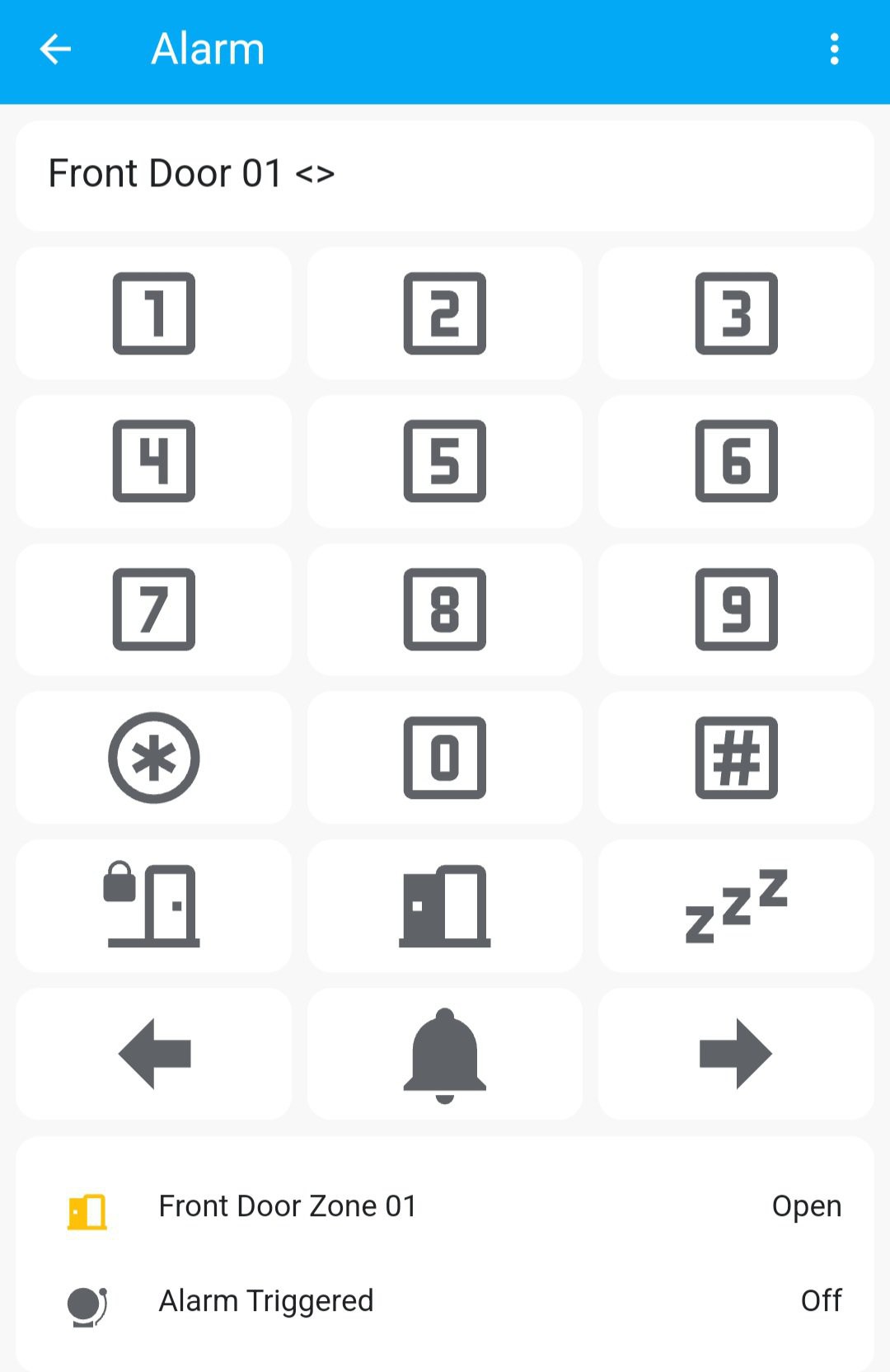
I programmed my ESP32 to subscribe to a specified MQTT topic for button pushing and listen for messages published by Home Assistant that would trigger the ESP32 to call the button pushing function with the appropriate XY coordinate and length of push parameters. Lastly I created the virtual keypad in the Home Assistant dashboard using a grid of buttons and a markdown box to display the lcd message.
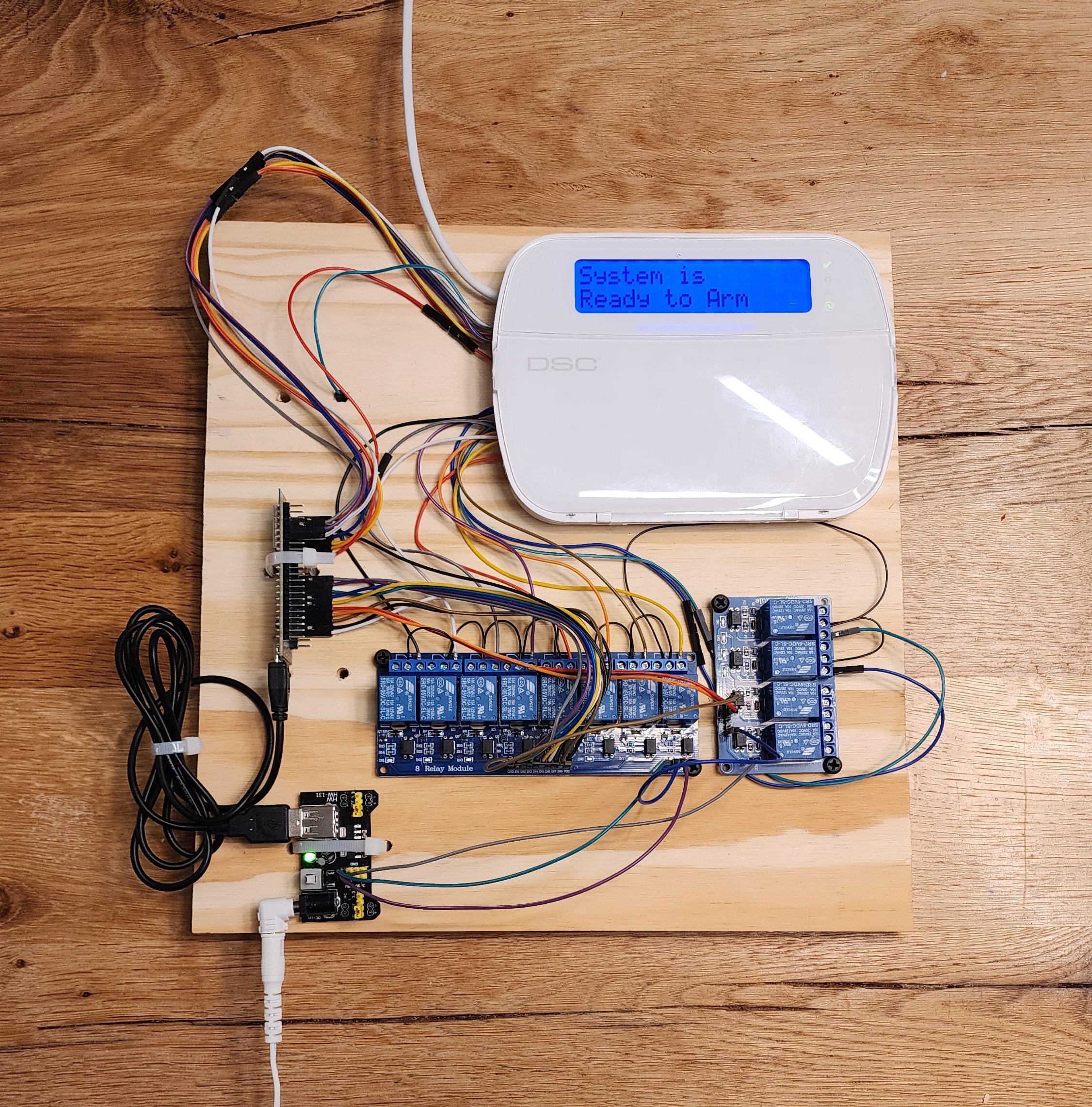
The virtual keypad integration now fully worked, but the relay modules and wires were ridiculously cumbersome, large, and required a separate 5V power supply. I had to miniaturize everything to make it more practical - although I did enjoy the audible clicks of the relays like an early computer clicking away.
Here is a picture of my first working prototype using 5V relay modules and an external power supply:
The virtual keypad in Home Assistant with a markdown box for the lcd status and a grid of buttons for the keypad buttons:
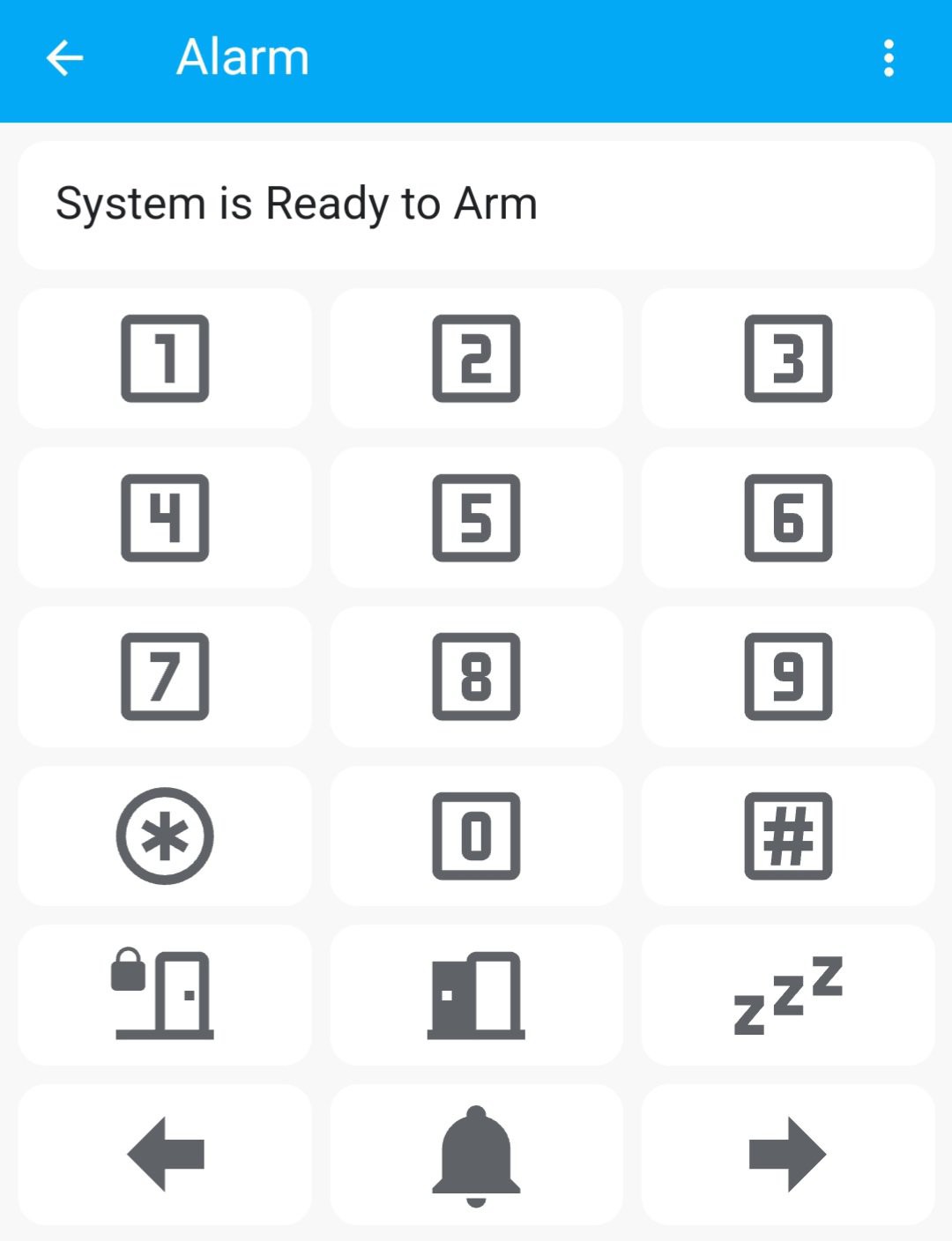
I was also able to get the stock Home Assistant Alarm Panel Template working but I found the virtual keypad much more functional as the alarm panel template only gives you the armed state and allows you to arm/disarm. The virtual keypad behaves exactly like a physical keypad would. You can even program the panel remotely from Home Assistant.
Part 3 - Honey I Shrunk the Integration:
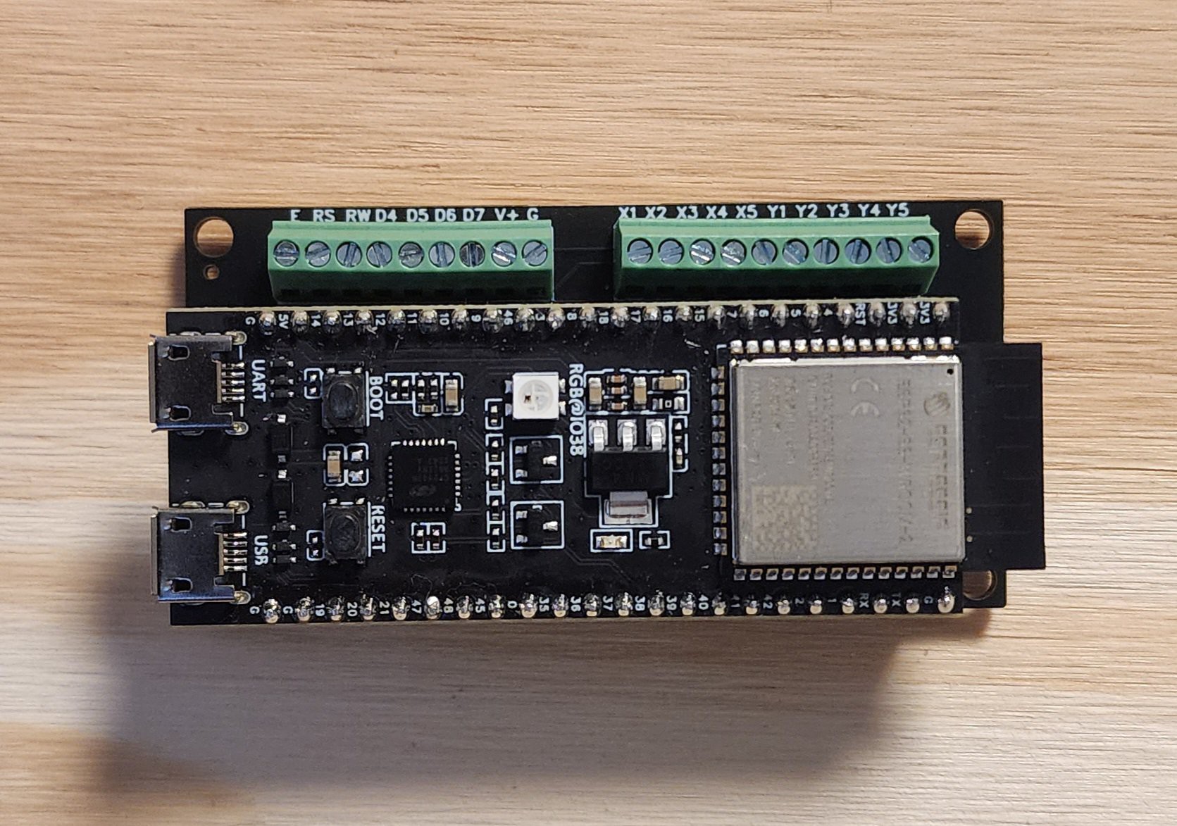
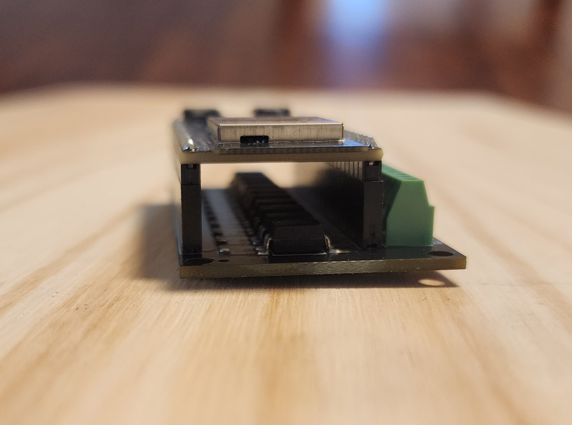
I needed to shrink things down to something more practical. The plan was to substitute optocouplers for the relays, and design a custom PCB that the ESP32-S3-DevkitC-1 dev board being used would plug into. I designed a compact PCB with an array of 10 PC817 optocouplers, female headers for the ESP32 devkit, and terminal blocks to make the connections to the keypad. Because the headers raise the ESP32 devkit above the board the optocouplers were conveniently placed under the ESP32, reducing the size to roughly the same footprint as the devkit itself.
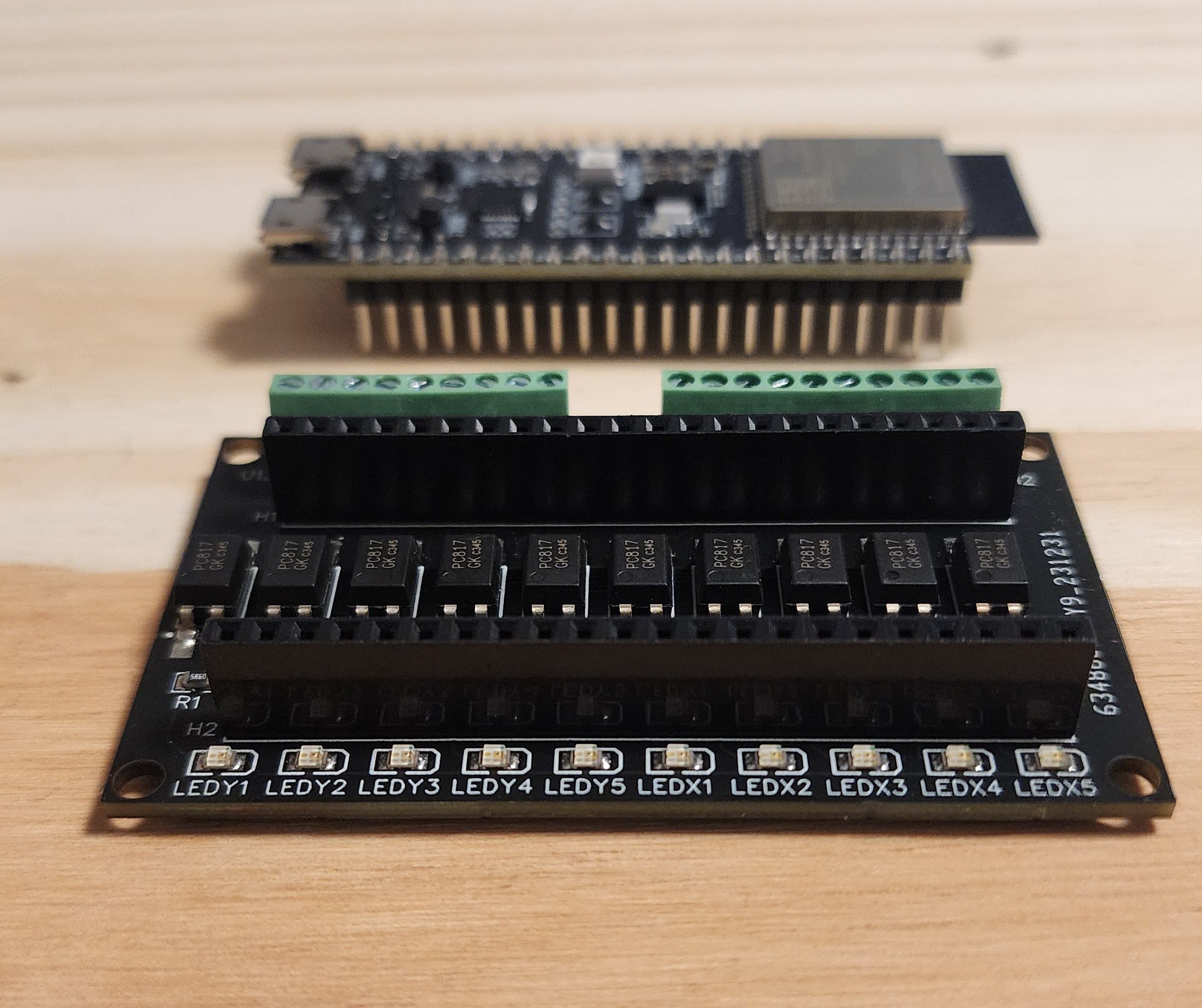
The first version I created had indicator LEDs for each optocoupler to identify which coordinates were being called. This worked well but combined with the LEDs inside the optocouplers I was really pushing the limits of the 3.3V output of the ESP32 GPIOs, and running the LEDs and optos in parallel would have required adding 10 more resistors to the board. I ended up re-designing it without the indicator LEDs which reduced the size further and the GPIO voltage demands. I also discovered that without the 5V relays, the entire module could run off the Keypad's +3.3V source and so in another revised version, +3.3V and Gnd were added to the terminal blocks so no external power supply was required. The integration was now just slightly larger than the ESP32 devkit board itself and significantly more practical. It could easily be hidden behind the device in the wall cavity. Future plans are to continue to try to reduce the size to have the entire package fit within the Keypads plastic case.
I added some code to the ESP32 to allow it to enter into a WiFi Access Point mode with a web interface to easily set up and change the WiFi and MQTT login/password settings. I also added some failsafe code so that the ESP32 will reconnect itself if it ever loses its connection to WiFi or MQTT, and will even reboot if it cannot reconnect within 30 seconds to ensure it always stays connected to WiFi and MQTT. The main RGB LED changes color depending on the connected state or modes (blue in this case means WiFi & MQTT are connected).
Part 4 - Adding Zone Status Functionality:
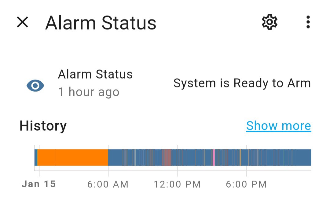
The last thing to do was to add zone status functionality so that the faulted zones or alarms can trigger other automations in Home Assistant. Although this relies entirely on the messages displayed on the keypad lcd it is very responsive and quick. In the Neo Keypad settings you can turn on the auto scroll function which automatically scrolls through any faulted zones displaying them to the keypad very quickly. For this to work you will need to know exactly how each zone is displayed on your keypad as everyone's keypad will likely have different descriptions programmed for each zone. It is best to copy and paste the message received by MQTT to ensure you have all the characters including spaces. You can easily see all the zones by scrolling through the list of zones to bypass.
To integrate the zones, I first created a binary sensor for each zone that responds to the keypad lcd displaying that particular zone is faulted.
For example, for a door on zone 1:
- binary_sensor:
- name: Zone01
state: >
{% if is_state('sensor.alarm_status', ('Front Door 01 <> '),) %}
on
{% else %}
off
{% endif %}
However this will turn the sensor on as "Front Door 01 <> " flashes on the keypad lcd screen but then it will turn the sensor off when the lcd displays something else even if the door is still open. Therefore the sensor blinks on/off while the door is open, which is not ideal.
What I need is for a sensor to latch on while the door is open and then turn off when the door is closed. To latch the state I added a corresponding Input Boolean and used automations to latch them on when the binary sensor is detected turning on, and off when either "System Is Ready to Arm" is displayed or when the binary sensor doesn't turn back on for at least 6 seconds. The 6 second rule addresses when multiple zones are triggered, as Ready to Arm will not display with other zones faulted, but the zone at issue may have been restored while other zones are still faulted. This way if the automation doesn't re-see the zone within 6 seconds in the scrolling list of faulted zones it assumes its closed. You can change this time to any length but I found 6 seconds worked well for many zones being faulted. A more precise method would be to have the code check between the displaying of "Scroll to View <> Open Zones" to see if the zone re-appears in the scrolling list as that message signifies the start/end of the scrolling list. My Yaml programming skills are limited so the 6 second rule works well for me. I also have a bypass sensor that tells if the keypad is in bypass section of the menu or not, so that it doesn't trigger the zones are open as your scrolling through the list of zones to bypass. The input boolean and automation code as follows:
Configuration.yaml:
input_boolean:
zone01:
name: Front Door 01
icon: mdi:electric-switch
Automations.yaml:
- id: '1234567890'
alias: Zone 01 Front Door
description: Front Door Zone 1
trigger:
- platform: state
entity_id:
- binary_sensor.zone01
from:
to: 'on'
condition:
- condition: state
entity_id: input_boolean.zonebypassmode
state: 'off'
action:
- service: input_boolean.turn_on
data: {}
target:
entity_id: input_boolean.zone01
- wait_for_trigger:
- platform: state
entity_id:
- binary_sensor.zone01
to: 'off'
for:
hours: 0
minutes: 0
seconds: 6
- platform: state
entity_id:
- sensor.alarm_status
to: 'System is Ready to Arm '
- service: input_boolean.turn_off
data: {}
target:
entity_id: input_boolean.zone01
mode: single
Lastly I added another binary sensor that tracks the state of the latching input Boolean. I do this because I don't want the on/off toggle switches on my zones and I want to utilize the various device classes of the binary sensors to show if it is a door, window, motion, garage, etc. There is probably a more elegant way to code this all using variables, but it works.
- binary_sensor:
- name: Front Door Zone 01
device_class: door
state: "{{ states('input_boolean.zone01') }}"
When programming motion sensors you will want the latch to stay on for a set amount of time. I found especially the wired motion sensors turn on and off so fast if you don't set the latch to a longer period you wont see them being triggered in your list of zones - although your automations will still be triggered.
I now have all my zones displayed in home assistant and they are very responsive to when the zone faults. Much more responsive than alarm.com is.
The Home Assistant Virtual Keypad after opening front door: