 mihai.cuciuc
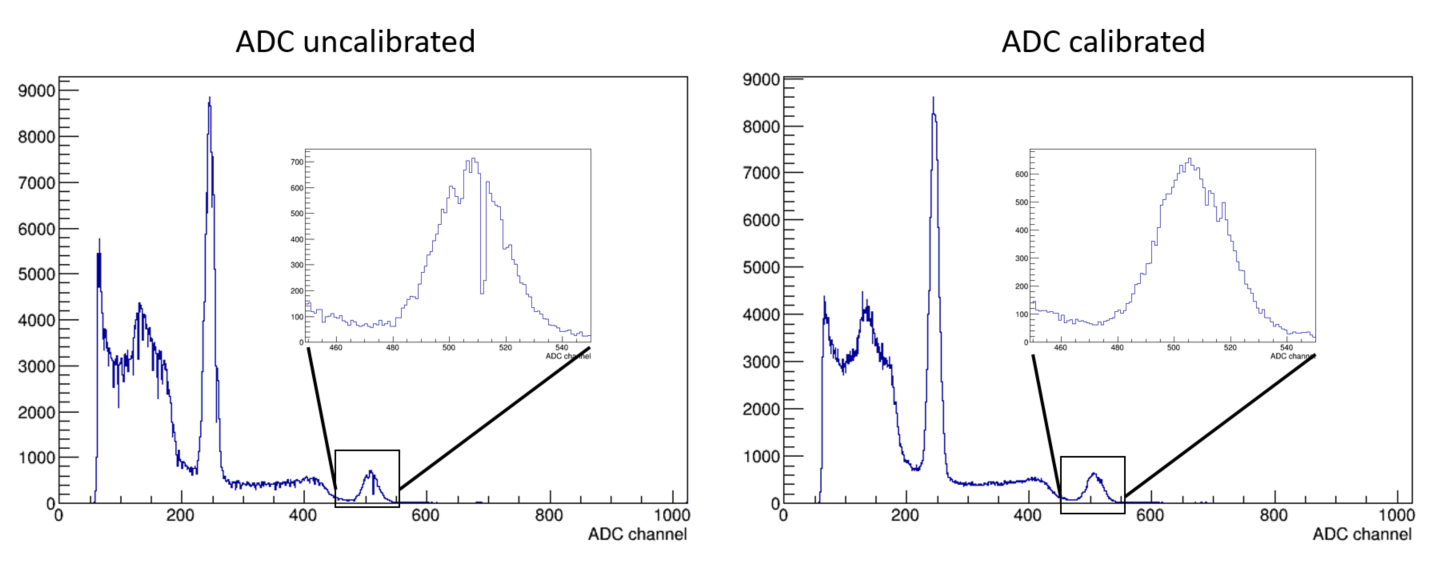
Plot on the left shows Na-22 source spectrum without ADC calibration applied, with a zoom on on the 1274 keV peak. Plot on the right has ADC calibration applied.
Missing codes
The 12-bit ADC in the SAML21 is great for most jobs. It can read voltages from tons of sources, has on-chip voltage references that it can use, and is reasonably accurate. But the ADC is quite stubborn in skipping some codes quite a lot. To test this, I generated some voltages with the DAC and took 100 measurements of them with the ADC. Most measurements look like the plot on the left in the following figure, with the measurements spread nicely around a center value. But in the middle of the ADC range is the worst culprit, with its plot on the right.
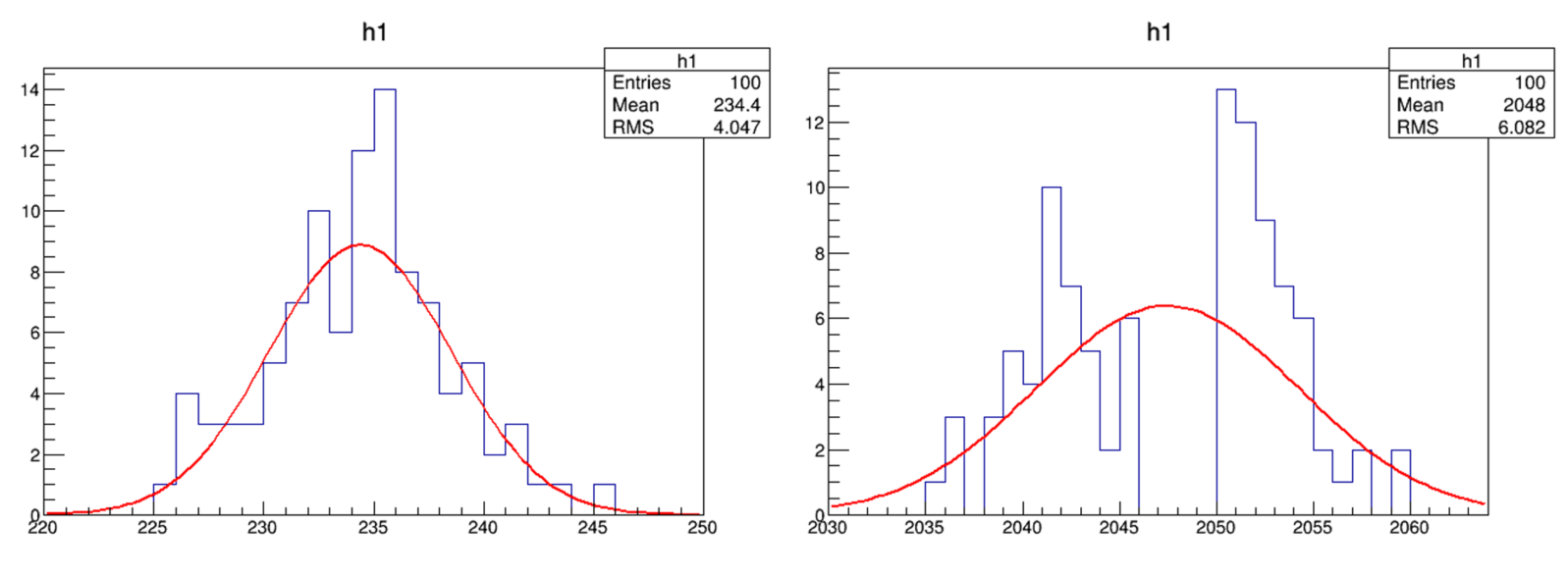
On the left is a histogram of some fixed voltage measurement with the ADC with a nice reasonable spread. On the right is a histogram of another fixed voltage, this time in the middle of the 12 bit ADC range. Four consecutive ADC codes are missing.
Mapping out the ADC response
With much higher statistics you do get some counts in those codes eventually. But it’s not just those 4 codes in the middle that are underrepresented. I wanted to get a map of all underrepresented codes, but I did not trust that the DAC is perfect and didn’t want to mix the two imperfections. I decided to use a very slow ramp generator to swing across the ADC range while taking as many readings as possible. That should ideally produce a flat histogram. I also wanted my ramp generator to be simple enough to integrate on the PCB as part of a “self calibration” tool. I ended up with a very simple op-amp integrator.
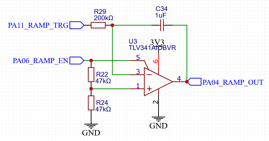
Ramp generator for checking the ADC underrepresented codes. It can be completely disabled from the MCU to save power.
Taking a LOT of ADC data using the ramp generator produces the following histogram which shows the underrepresented bins. As I’m truncating my readings to 10 bits, now the troublesome middle of the ADC range is at bin 512.
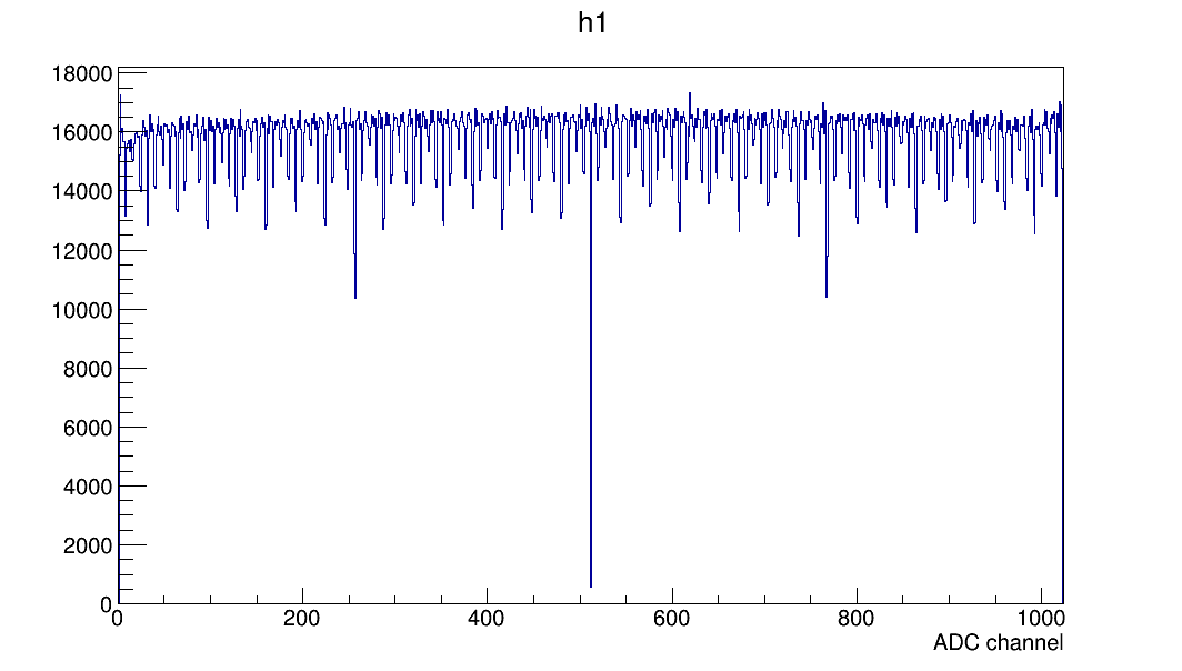
Histogram of the ramp generator readings showing periodic underrepresented codes in the ADC.
Correcting for missing codes
This structure gets imprinted on the gamma spectra I gather and make them look unpretty. Realistically it’s not a huge problem, as the detector resolution is low enough that these structures can safely be ignored. It’s still obvious where the gamma peaks are even if there’s a gap right in the middle of one, as can be seen in the first plot at the beginning of this log. But I still want it fixed.
My first thought was to run some smoothing on the spectrum, with a moving average window. That did not work great as the dips were still visible, and it also started worsening the energy resolution of the measured peaks. Not cool.
Then I tried multiplying the gamma spectrum with the inverse of the calibration histogram. This did make the spectrum look pretty, but I did not like the thought of presenting an altered version of the histogram that the one I store in memory. Plus, since it involved integer division you could present a histogram that has a different integral than the total number of pulses you measured. Also not cool.
I wanted a solution that would work on an event-by-event basis -- whenever I have a measurement, place it in an appropriate bin such that the end result is a pretty histogram.
Calibrating the ADC - donor and acceptor bins
Whenever I get a gamma reading from the ADC I want to be able to quickly decide if I should place it in its corresponding histogram bin, or to give it away to one of the neighbouring bins to smooth out the resulting spectrum. Physics-wise this is not such a big deal -- each bin is ~2.5 keV, whereas the detector resolution is ~60 keV. So “misplacing” a reading a few bins left or right is ok.
For the rest of this section let's assume I just got a gamma ray measurement, and the ADC reading is 509.
I look in the calibration histogram at 9 bins centered on the one corresponding to the measurement, shown in the following plot.
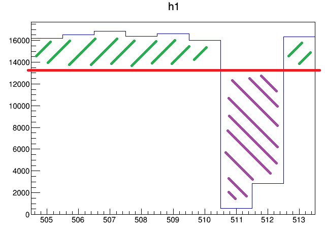
A slice of the calibration histogram that is used whenever the ADC takes the reading 509, to evaluate what to do with this measurement. Should I keep it in bin 509, or give it to a neighbouring one?
To decide where the current measurement (509) goes I first check if bin 509 in the calibration histogram is underrepresented, that is if its value is less than the local average of the 9 bins. The local average in the picture above is the red line. If the bin is underrepresented (not the case for bin 509), I always place the measurement in that bin – I don’t want to further deprive the already underrepresented bin of any counts.
In this case, bin 509 is above the local average, so it is a donor bin – it will give some of its samples away. To compute the probability that it will give a sample away, I take the ratio of the green hashed part of bin 509 to the total height of the bin, so very roughly 20% in this case. Using a random number draw I decide to keep ~80% of the samples in bin 509 (I don’t want to over-deplete it), and I give ~20% of them away. If the random number said I should give it away, I use another random number draw to decide which neighbouring bin I should give it away to. Only the ones which are below the local average are eligible -- the purple hashed ones. Their probability to be acceptors is proportional to how badly they need it, so it’s more likely for the sample to end in bin 511 than in bin 512. Applied on a large enough number of samples, this algorithm should trim the green hashed bit in the plot and use that to fill in the holes in the purple hashed bit. All the probabilities I mentioned above are precomputed, so for each measurement the algorithm only has to draw one or two random numbers and make a few comparisons. But this does result in a HUGE calibration array that takes up 18 kB of program space.
The following plot is an overlap of the first two plots in the log, showing that the energy resolution does not get significantly worsened by this form of weighted dithering.
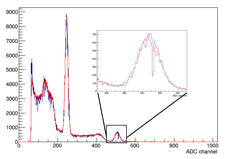
Two datasets taken with a Na-22 source. Red plot is with ADC calibration applied, blue plot is without. Inset shows details on the 1274 keV peak.
Discussions
Become a Hackaday.io Member
Create an account to leave a comment. Already have an account? Log In.