0%
0%
Sound-activated Counting Light
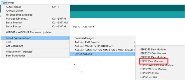
This is a guide for new of esp32 and arduino, in this article, I will share how to make a sound-activated counting light.
 Makerfabs
Become a Hackaday.io member
Already have an account? Log in.
Just one more thing
To make the experience fit your profile, pick a username and tell us what interests you.
Pick an awesome username
hackaday.io/
Your profile's URL: hackaday.io/username. Max 25 alphanumeric characters.
Pick a few interests
Projects that share your interests
People that share your interests


 UTSOURCE
 Songkord Thirachai
 Hulk
Hulk