 mit41301
OBJECTIVE:
The objective of the project is very simple. Make a Single Chip Computer running BASIC-52 using enhanced 8051 core. The board form factor should be equal and compatible with existing DIP-40 600 mils package. The available pins should be mapped to the original DIP-40 package pinout.
The circuit should be very minimal. If possible run with only a single chip.
PROs:
- Single chip solution without any external components.
- No external address latch
- No external RAM required. Uses internal RAM for BASIC and program
- No external Crystal or Oscillator required. Running at 24MHz internal oscillator
- No external programmer required. Programming via USB or UART
- PORT1, Tx, Rx, Timer, Interrupt, pins available for user interface!
- Runs 8~15 times faster than conventional controller
CONs:
- Limited Memory
- No external memory
We can easily overcome the limitations using CH558 or CH559 controllers. Using CH558/CH559 controllers gives the speed advantage of 2x since running at 48MHz. CH559 comes with 6kB RAM which is good enough for most of the programming needs.
The following description shows how we can implement a BASIC-52 single chip computer using CH552 IC. CH552E comes with MSOP-10 package. It is just 3x3mm size. But the number of useful I/O pins are just 4. CH552G comes in SOP16 package. It has more I/O pins compared to CH552E. Same thing applicable to CH552P IC. CH552T comes in TSSOP-20 package. It is having 20 pins and having highest pin counts in the CH552 family. CH552 family comes with 16kB FLASH and 1288 bytes Data Flash or RAM.
CH552E does not have UART0 pins mapped to physical IC. So we need to reassign the UART0 traffic to UART1 in the source code.
The souce code was modified by Twitter(X) user @hiyodori5
You can also find CH552E, CH559 code in his Twitter feeds. CH559 code also supports SPI bus apart from I2C bus.

CONSTRUCTION:
If you just want to run the BASIC-52 on single chip, you can use any of the commerical available boards which using CH552E, CH552G, CH552P or CH552T. We can also run the CH559 code on CH559 eval or dev boards.
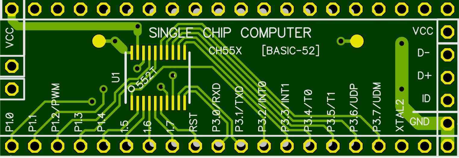
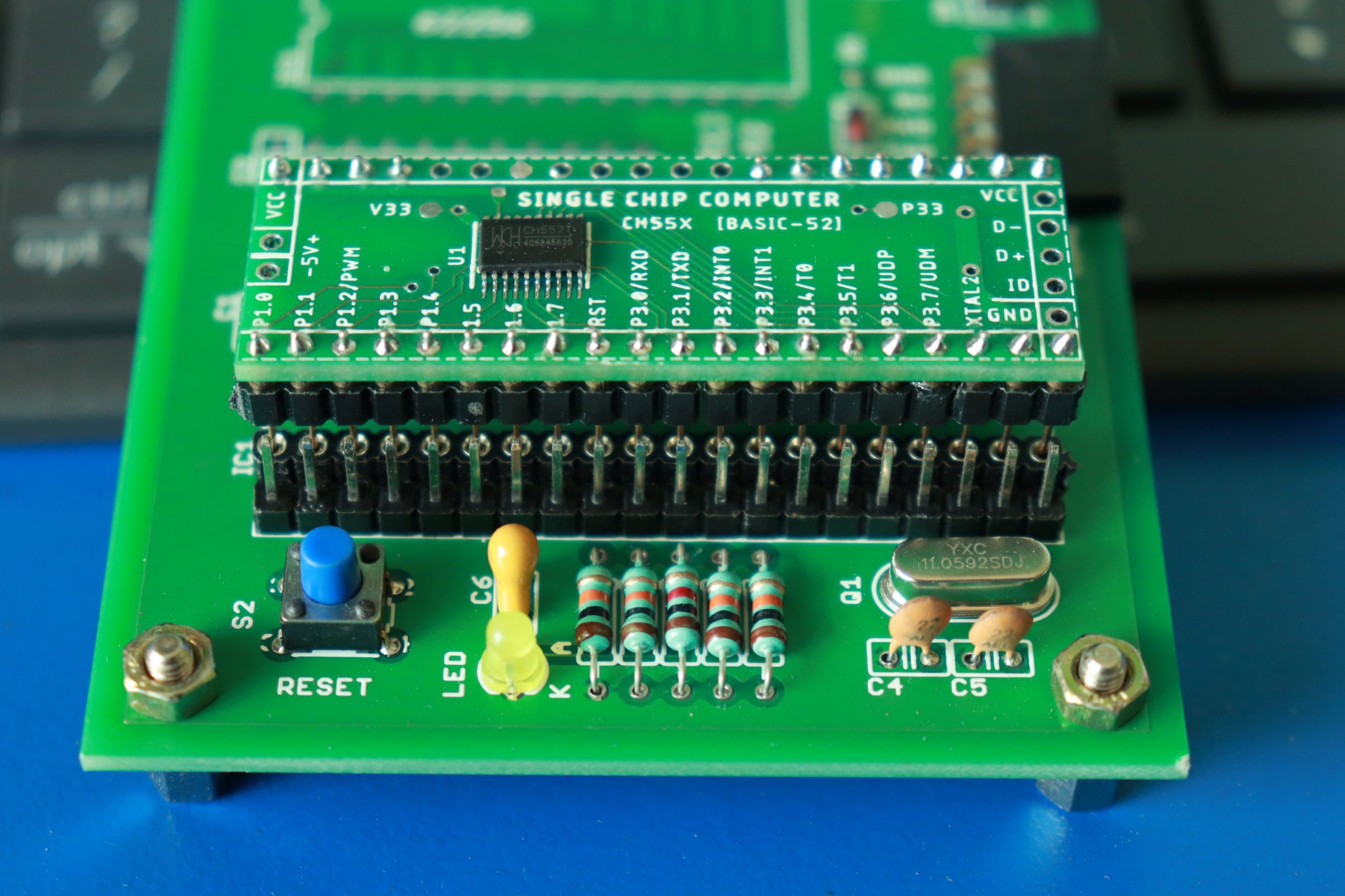
The above image shows the board form factor and pin assignment. Since the board was made in DIP-40 size and pins compatible with the original pinout of the 8052 IC. The board is very simple and can be fabricated on two layers. The fabricated board looks like below.
Power supply pins are VCC at pin 40 and GND at pin 20. PORT1 pins 0~7 available which is very useful for interface. Port 1 pin 2 also serves as PWM output which is useful to make any PWM based control or just create some noise or sound using buzzer/speaker. Hardware Reset pin is available. RxD and TxD pins available for primary communication. INT0, INT1 pins are available. T0, T1 pins are available. P3.6 and P3.7 pins are available. P3.6 and P3.7 are useful for programming the device Flash memory.
We need VUSB capacitor and proper supply decoupling for reliable flash programming through USB port. After programming BASIC-52 code, since we are not going to use the USB port anymore, we don't require the VUSB capacitor. By this way we can achive the real 100% Single Chip Computer using BASIC-52. The Flash programming cycle endures for around 200 times. Since we are going to flash only once, we need not to bother about flash programming anymore.
Since there is lot of space and no other components required, I don't want to go for fabrication with no other features. So I have decided to add onboard USB-TTL converter. We can directly connect the Single Chip Computer to PC using 4 connections VCC, GND, D- & D+ pins.
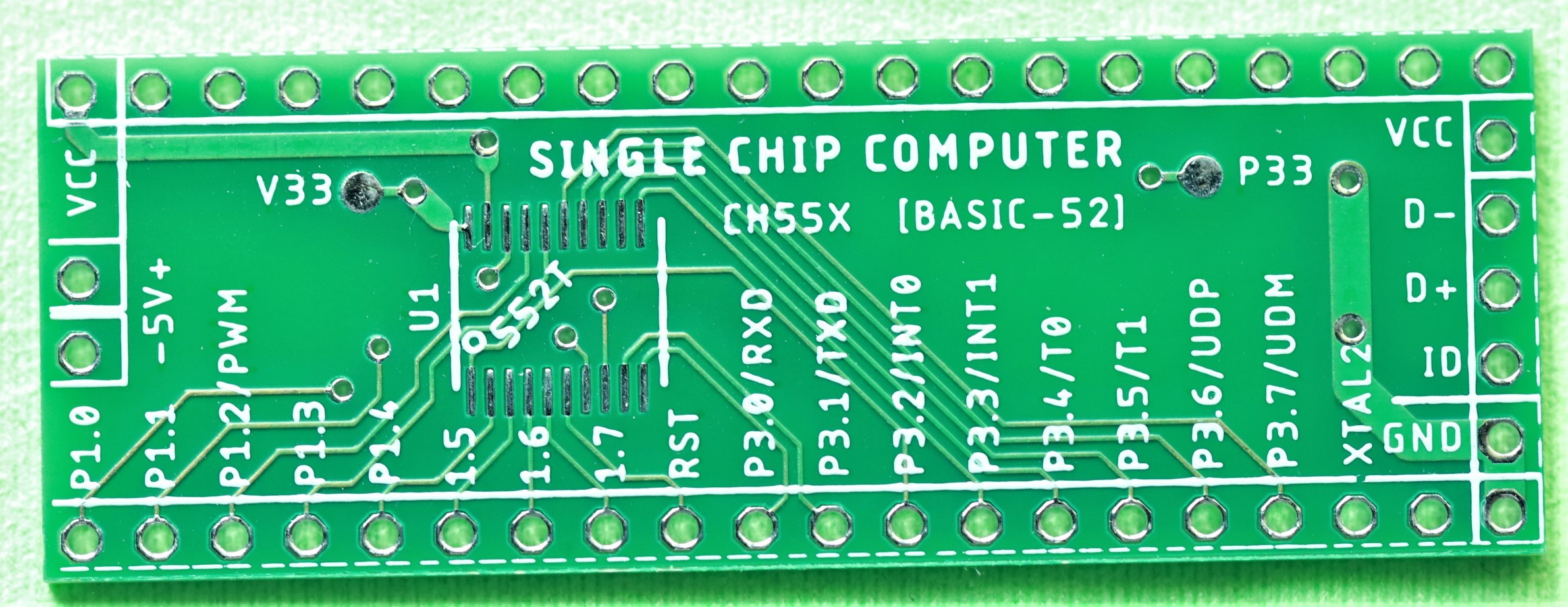
The assembled and firmware loaded board looks like below.
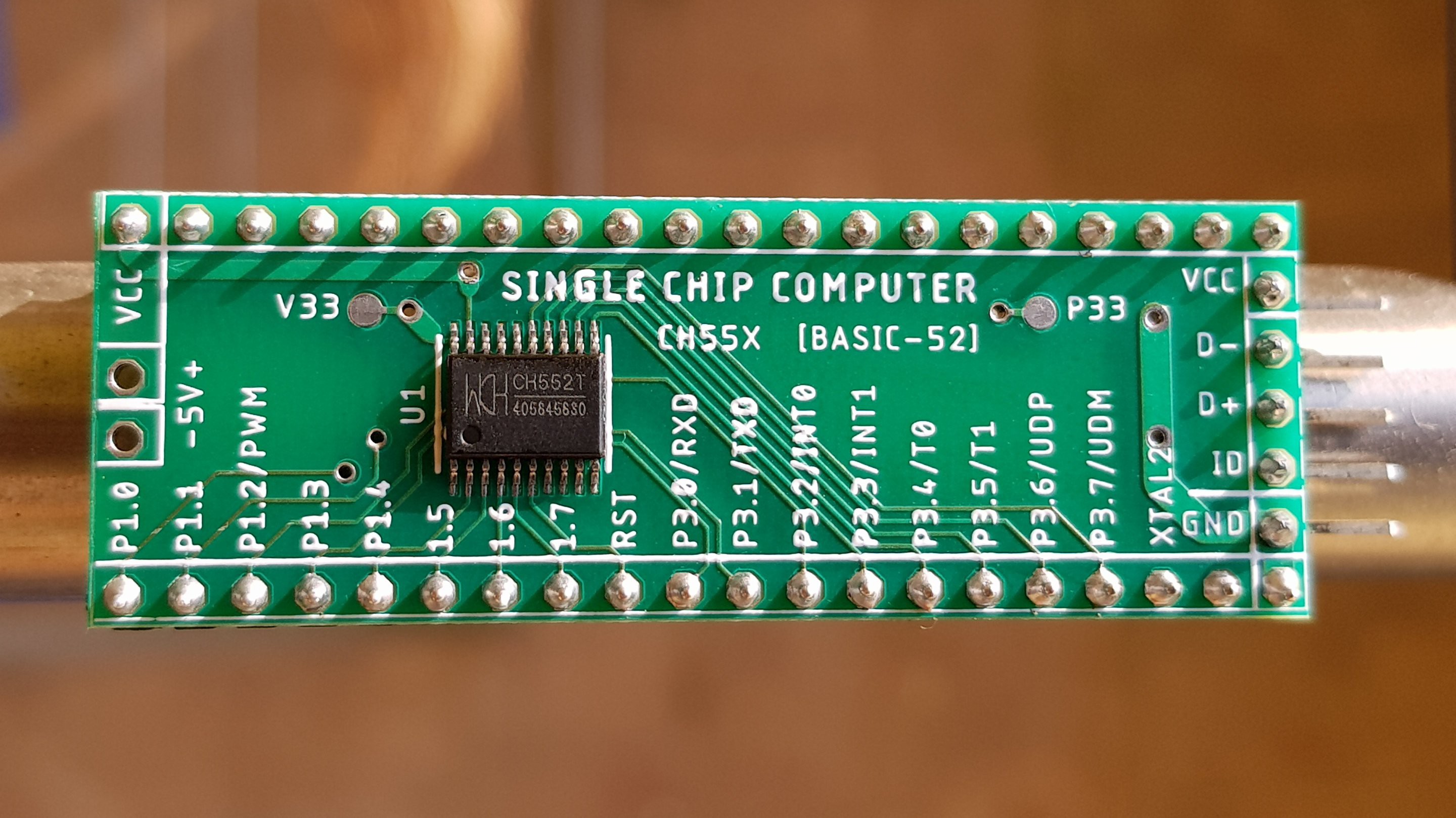
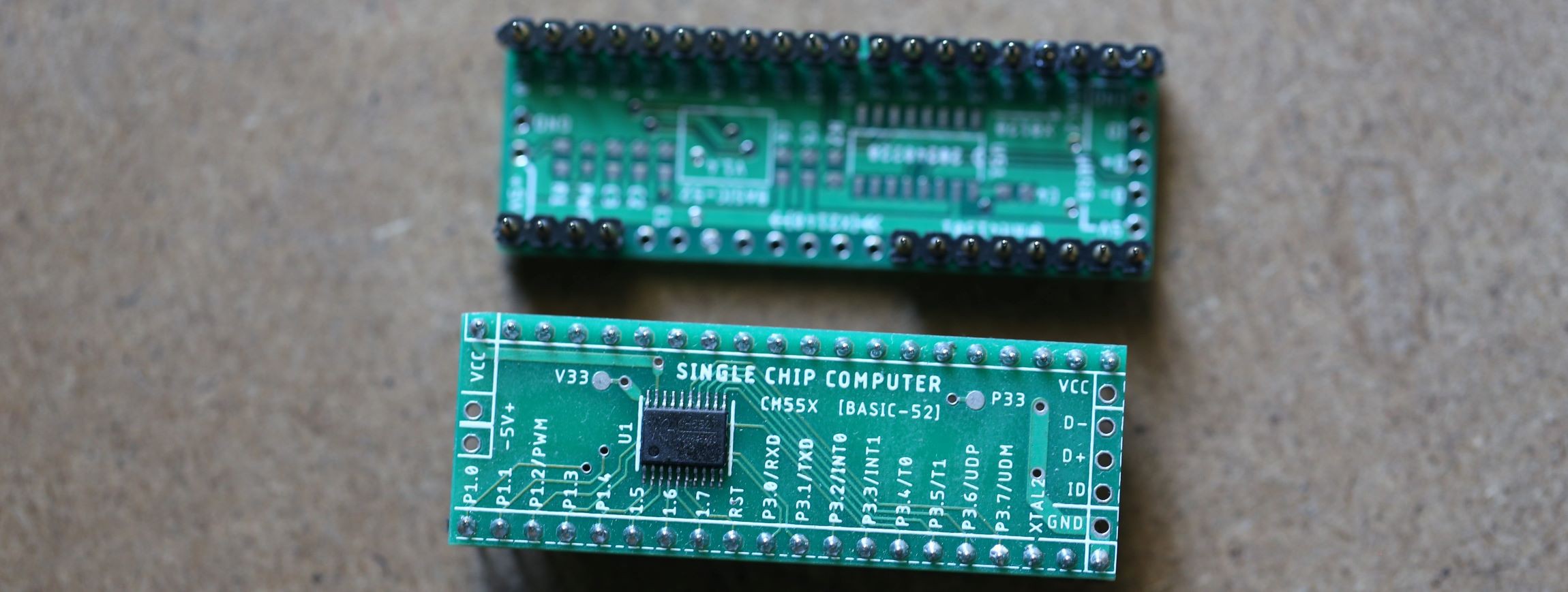
Both top and bottom side view. In the top side only one chip needs to be assembled. Bottom side there is no components needed for wired and wireless operation. There is a optional inbuilt USB-TTL circuit on the rear side which is not required for normal operation.
If we notice closely, only 19 pins are mapped to the original DIP-40 IC version. Pin numbers 18, 19, 21~39 are not connected in DIP-40.
I have not added the caps on the TOP layer which simplifies the assembly process only because the title of the project "SINGLE CHIP COMPUTER"!
BLUETOOTH HC-05:
It is much easier and convenient to operate the computer over Bluetooth UART link using SPP

We can use any of the available serial port over bluetooth which supplorts 19200 baud. We need to check the default baud of the bluetooth modules using AT commands. If the default baud rate is not 19200, we need to set it. Most of the modules comes with the default baud of 9600. We can also change the Module Name from default name.
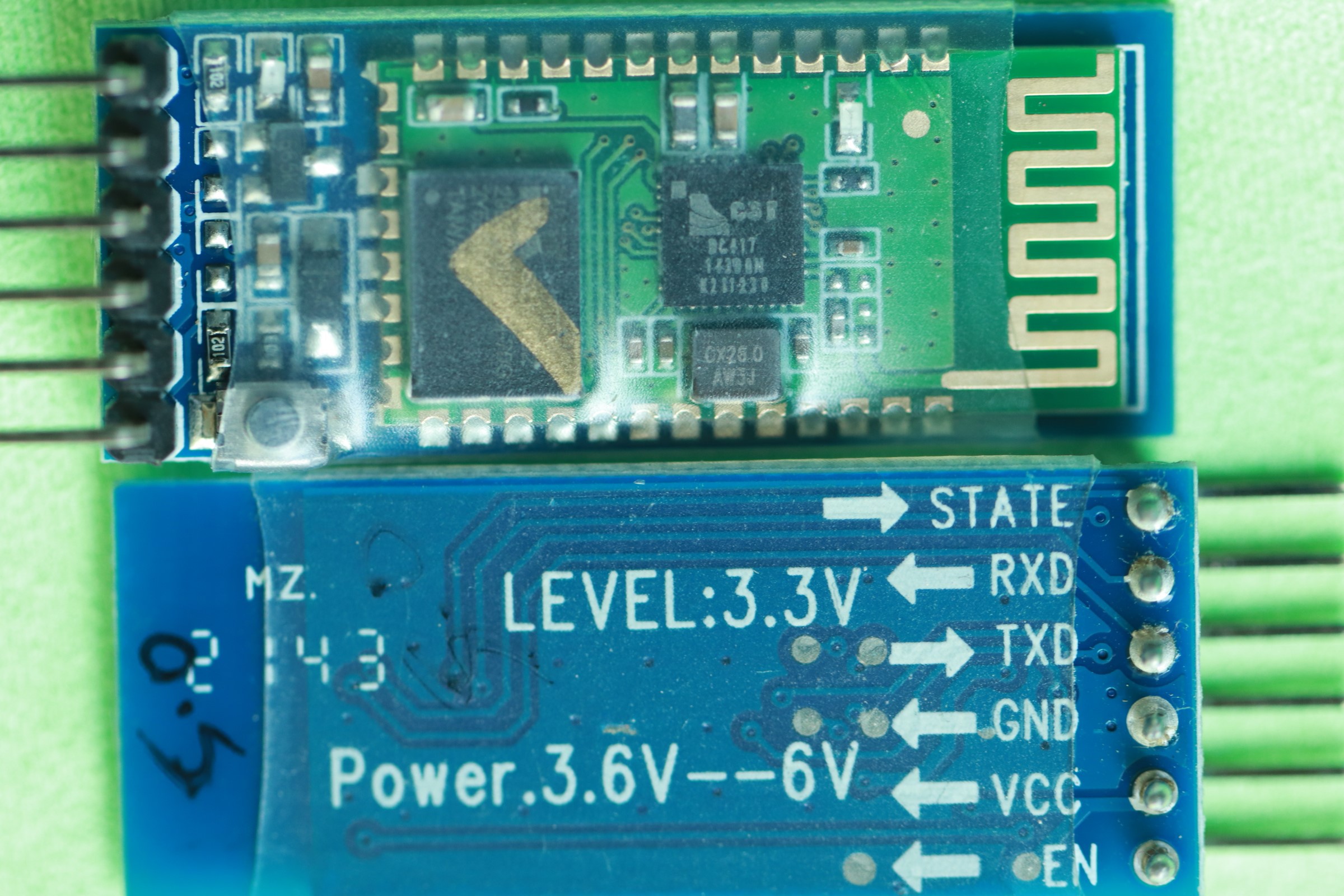
To enter into AT command mode, the EN or AT pin should be held HIGH to VCC. We need USB-TTL to connect the Bluetooth module to PC. Please refer to the vendor datasheet for available commands and connection.
KEYBOARD and MOUSE:
We can use wired USB keyboard and mouse with PC/Laptop or Smartphone as input device. We can also use Wireless 2.4GHz combo keyboard with receiver plugged into USB port of PC or phone.

Dual connectivity keyboard was used for testing the single chip computer. We can easily connect with Unifying receiver or through Bluetooth. We can easily swich between two devices by just pressing F11 or F12
MOUSE:
We can use wired mouse or wireless mouse. Tested the single chip computer using Bluetooth mouse.

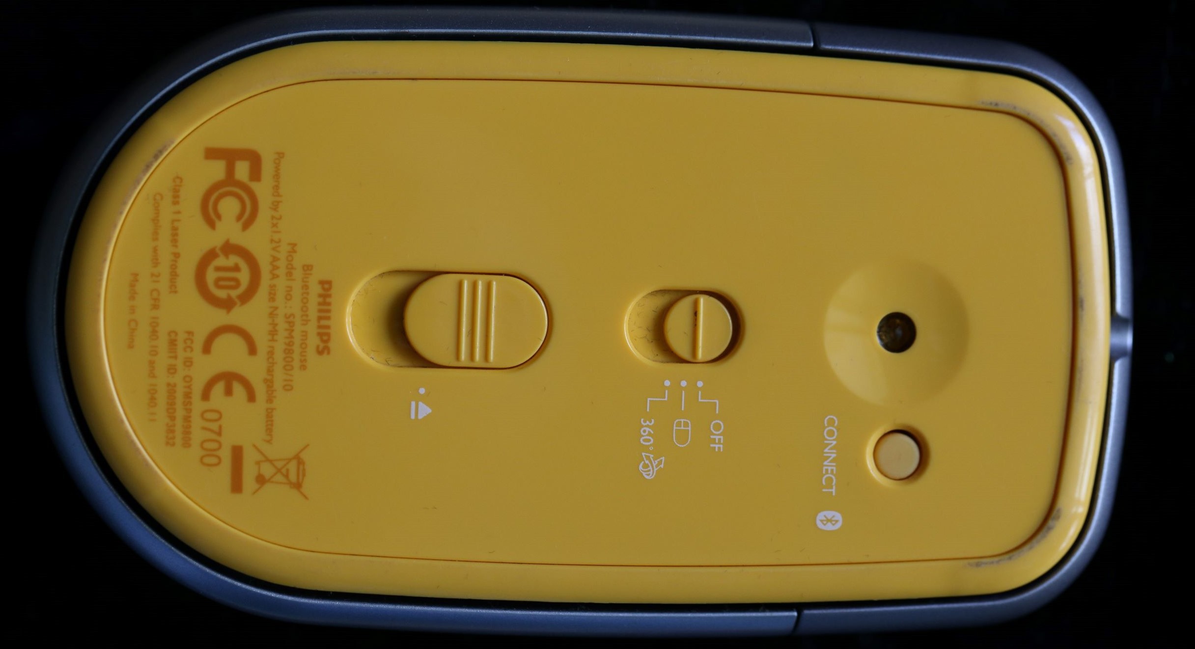
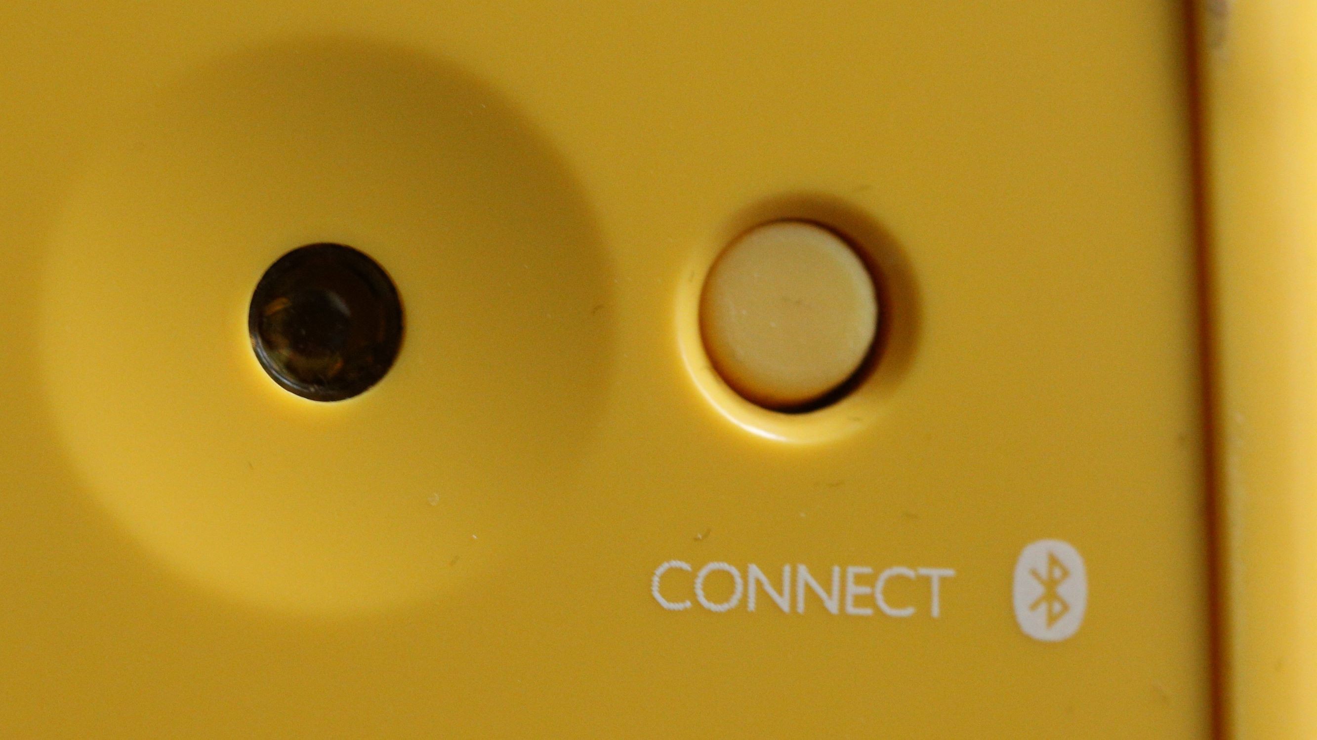
We need to press the CONNECT button for pairing the mouse with PC or Smartphone.
INTEGRATION:
We can use a base board for easy interfacing. The same board can be used for conventional 8052 controller available in DIP-40 package. Below picture we the Crystal is unused and electrically not connected with the single chip computer.
When we use Bluetooth UART module, refer to the vendor datasheet for connecting single chip computer.
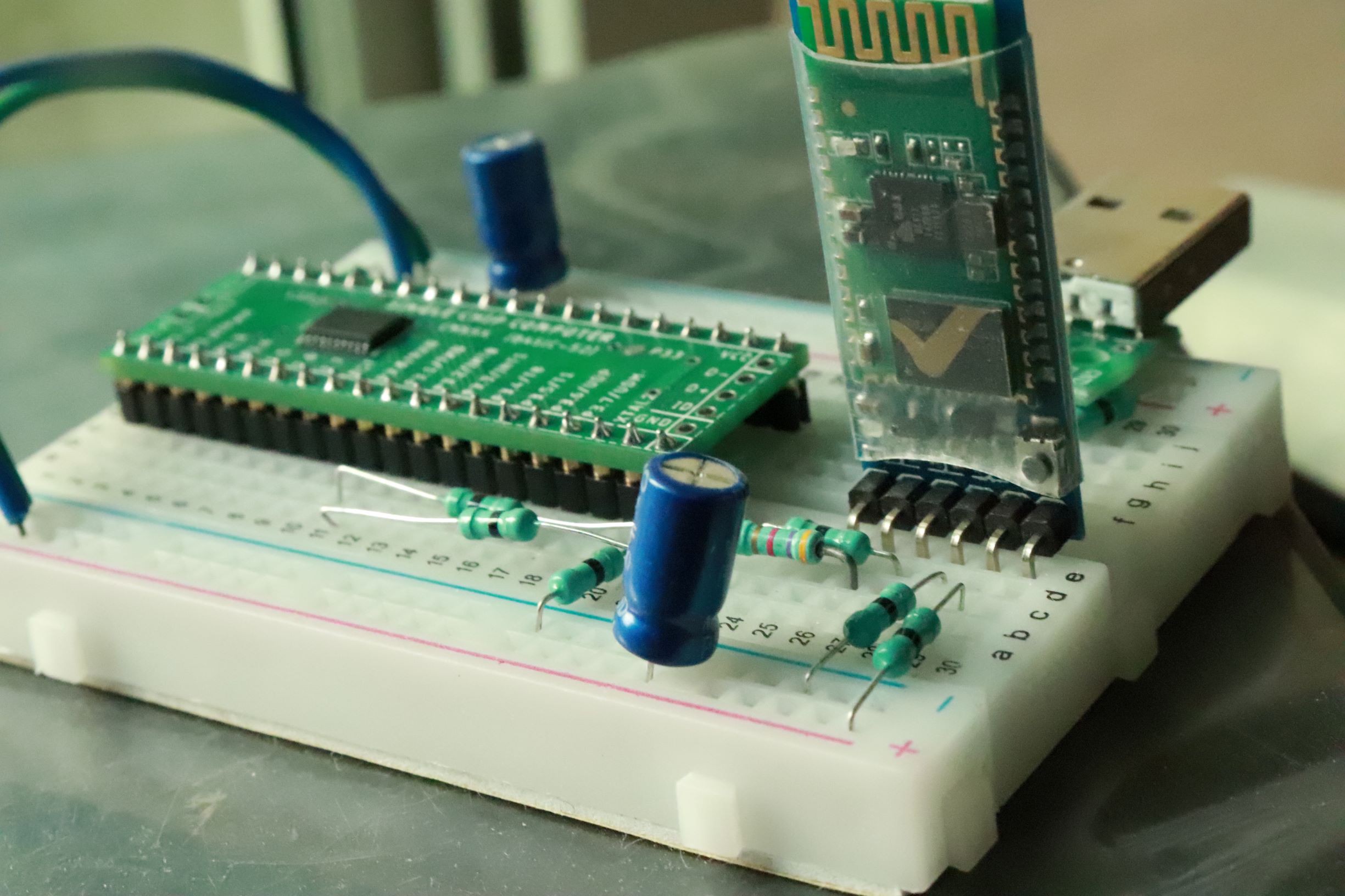
Both modules uses 5V power supply and Tx, Rx pins of the single chip computer and bluetooth module's Tx & Rx pins are connected as per vendor datasheet.
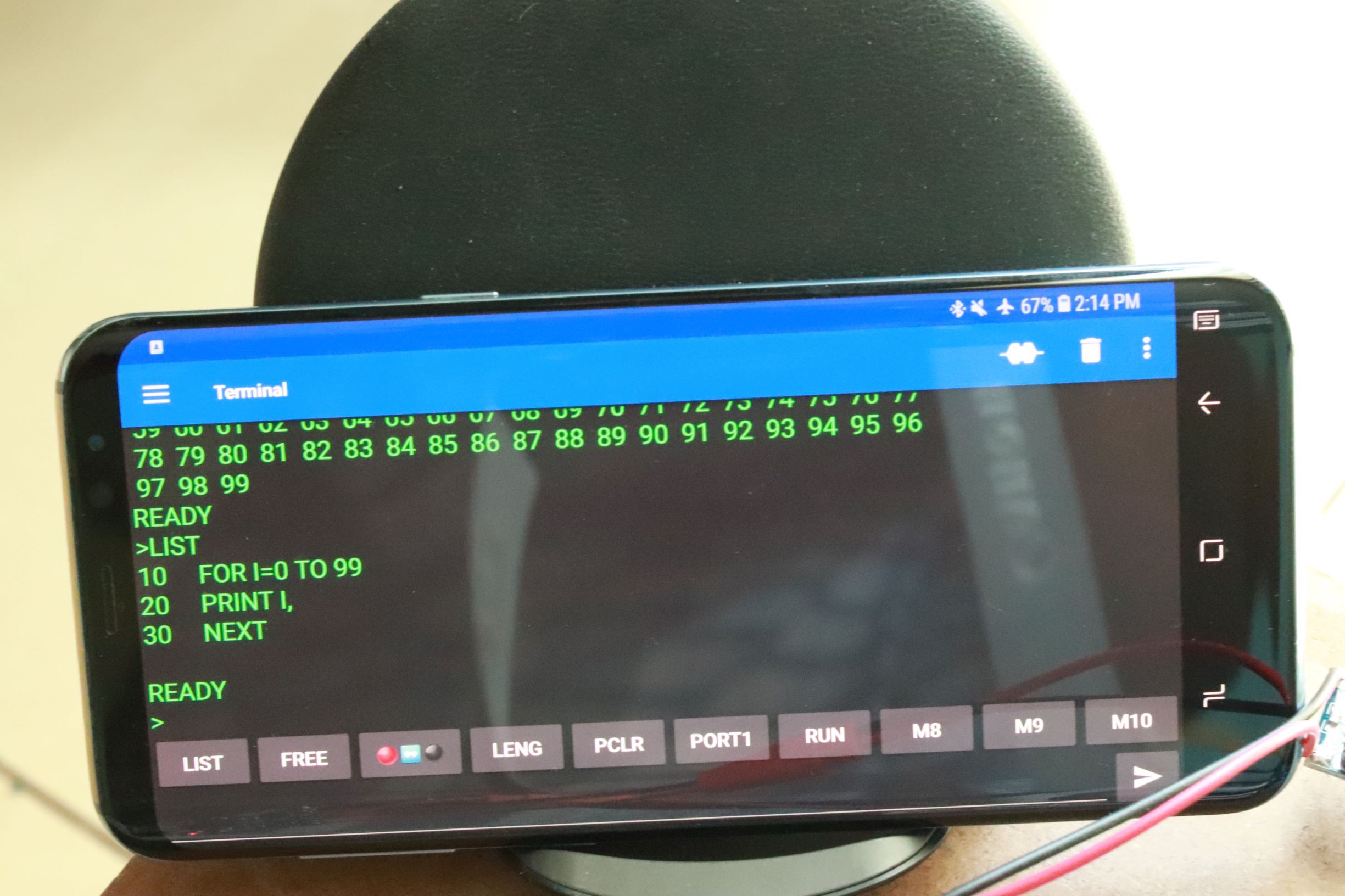
Here android phone used as monitor for BASIC-52 computer. This smartphone resting on wireless charging pad and charges wirelessly. We can also mirror the screen output into a smart TV for better user experience.
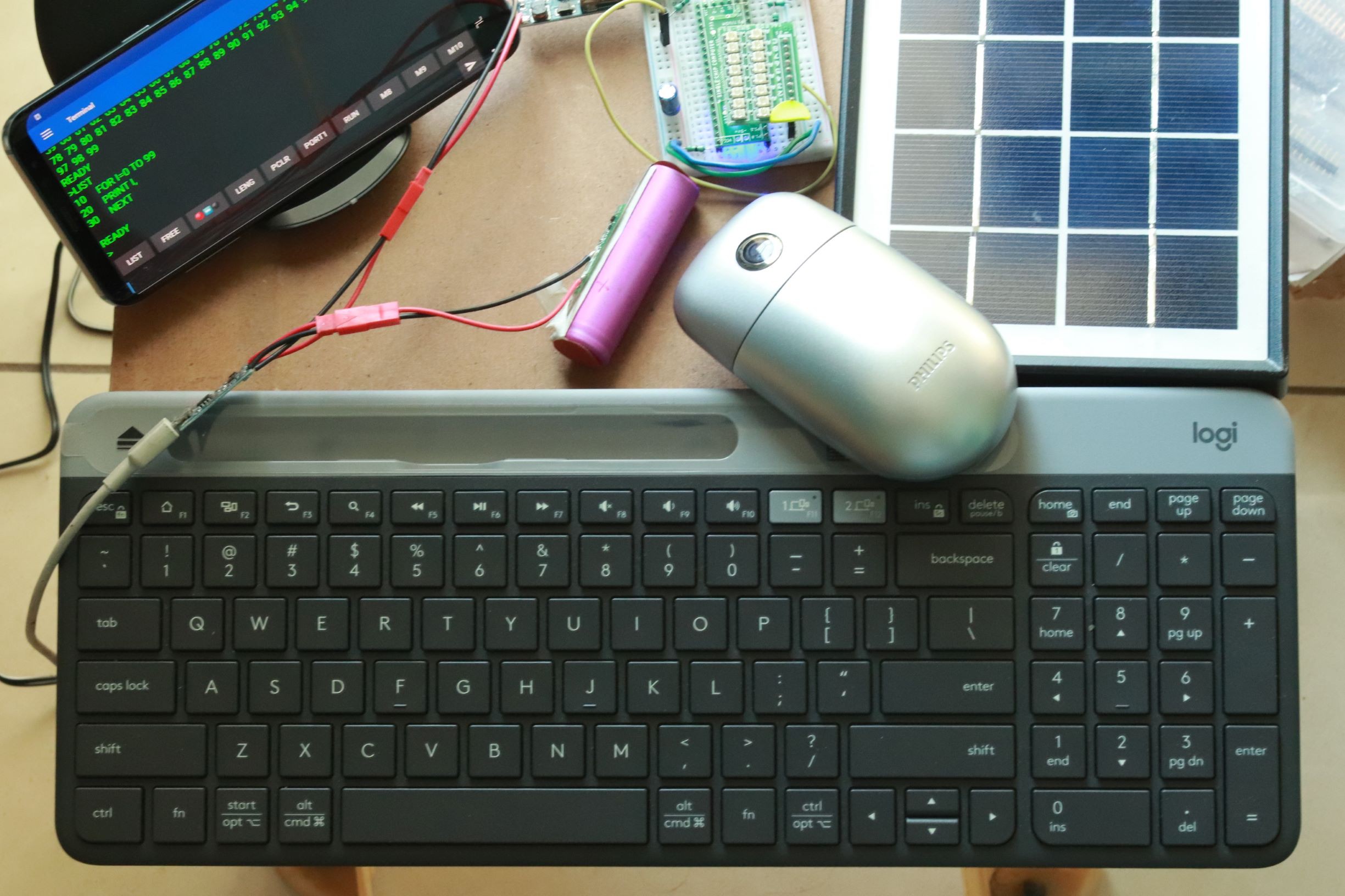
The complete setup looks like above picture. From solar panel the Li battery gets charged through charger board. From Li battery boost regulator with 5V output provides power to BASIC-52 computer. Single board computer and smartphone is connected with smartphone through bluetooth using HC-05 module. Both Keyboard and Mouse are connected with smartphone through bluetooth. There is no wires between computer, keyboard, mouse and smartphone. It works seamlessly.
POWER SUPPLY:
The single chip computer operates VCC at 5V. We can easily adopt the supply voltage from USB port or any other 5V source.
Since the single chip computer operates over bluetooth wireless UART link, we can keep and operate the single chip computer within the wireless range. For example you can keep the computer outside your house.


With this arrangement, we can operate the computer 24/7 independent of power outlet or Electricity.
To start programming or to understand the hardware, the following book is very simple and useful for interface and programming using BASIC-52.

This book is now available as a free PDF and having all the source code files are available as a single zip file.
The PDF COPY of the book available from HERE. The source code listing of the book from HERE.
So we need not to type anything. Just edit if you need and modifications and send the file through serial port using wired or wirelessly.
Apart from this you can also find the intel MCS BASIC-52 manual and all the versions of BASIC-52 freely available on many sites.
SOFTWARE:
Download the source code and assemble using ASM51 assembler which can be found along with source code files. We can also use C51ASM from Atmel(Microchip). Both ASM51 and C51ASM produces same checksum and assembles without any warning or errors. C51ASM availble as free download for windows and linux from Microchip's website.
The default XTALV defined in the code is 11059200 should be changed to 24000000. We can easily locate the source file code lines using SEARCH by "XTALV:" and change to 24MHz. We can also edit the HEX file directly with much care.
                    5920            ;CONSTANTS
                    5921            ;
17EC 88             5922    XTALV:  DB      128+8           ; DEFAULT CRYSTAL VALUE
17ED 00             5923            DB      00H
17EE 00             5924            DB      00H
17EF 00             5925            DB      00H
17F0 00             5926            DB      00H
17F1 24             5927            DB      24H
                    5928            ;
After booting with BASIC-52, we can make sure the effectiveness of the change by ?XTAL command.
Just connect the board using USB port VCC, GND, D+ and D-. Short the D+ pin and VUSB before applying power and release the link after applying the power. This may not be required for factory fresh IC connected to USB port. First time the IC will enter into bootloader mode by default without connecting D+ and VUSB.
Use any of the compatible programming tool to flash. I have used WCHISPTOOL from the vendor for Windows platform.
Connect any USB-TTL board with single chip computer. We can easily draw power VCC, GND from the USB-TTL board.
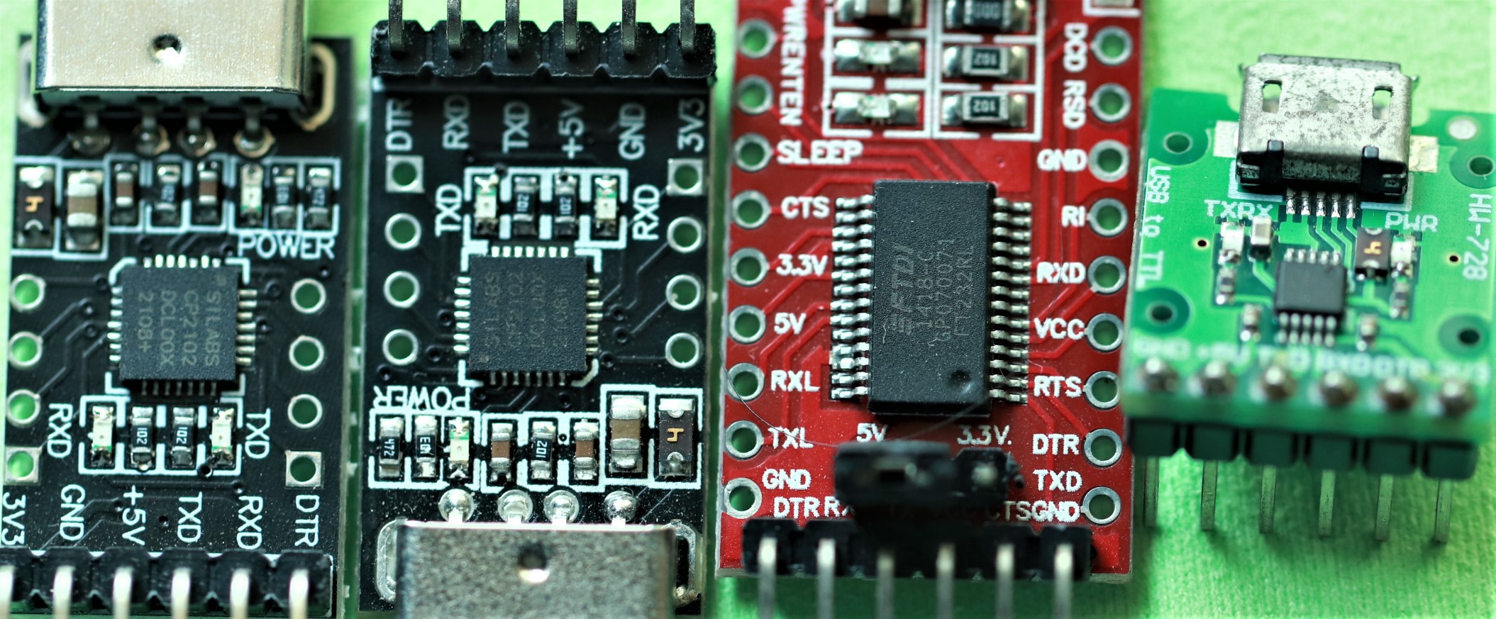
Connect Tx-Rx, Rx-Tx. Invoke any VCP terminal and set the baud to 19200. We need to define delay of 5ms and 50ms for character and line delay for reliable file download into single chip computer. We can use TeraTerm, Putty or any other serial terminal utility. We can also connect to smartphone using similar UART communication APP installed in the phone.
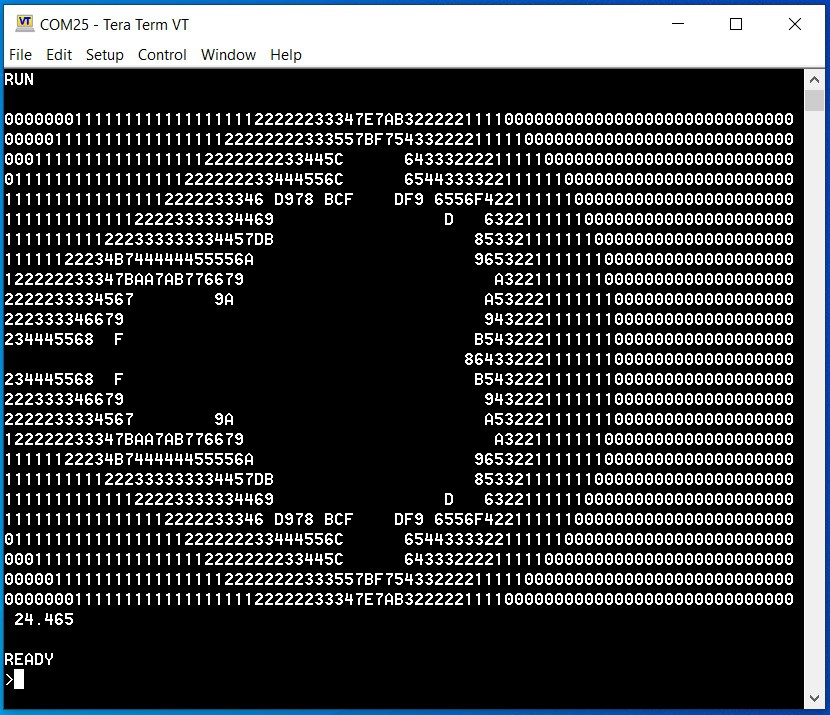
We will run ASCIIART.BAS which is a famous benchmark program. Remove line 210 for single RUN or press CTRL+C to break the endless loop.
01    REM ASCII ART
02    REM ASCII ART CH552T
07     XTAL=24000000
08     TIME=0 :  CLOCK 1
10     FOR Y=-12 TO 12
20     FOR X=-39 TO 39
30    CA=X*0.0458
40    CB=Y*0.08333
50    A=CA
60    B=CB
70    I=0
80    T=A*A-B*B+CA
90    B=2*A*B+CB
100   A=T
110    IF (A*A+B*B)>4 THEN  GOTO 150
120   I=I+1 :  IF I<=15 THEN  GOTO 80
130    PRINT " ",
140    GOTO 170
150    IF I>9 THEN I=I+7
160    PRINT CHR(48+I),
170    NEXT X
180    PRINT
190    NEXT Y
200    PRINT TIME
210    GOTO 10
220    END
The ASCIIART.BAS output is as below. The program can be executed below 24.465 seconds!
BLINK LED:
The following code toggles the P1.7 once per second. Make sure your XTAL value defined as 24000000 by typing ?XTAL in BASIC-52. If BASIC-52 returns 11059200 then we can add XTAL=24000000 in the code or change the source file for 24MHz.
10    REM toggles P1.7 once per second
20    TIME=0
30    CLOCK 1
40    DO
50    ONTIME 1,100
60    WHILE 1=1
70    END
100    REM reset time
110    TIME=0
120    REM toggle Port 1, bit 7
130    PORT1=PORT1.XOR.80H
140    PRINT "Port 1, bit 7 = ",(PORT1.AND.80H)/80H
150    RETI
L10-2.BAS
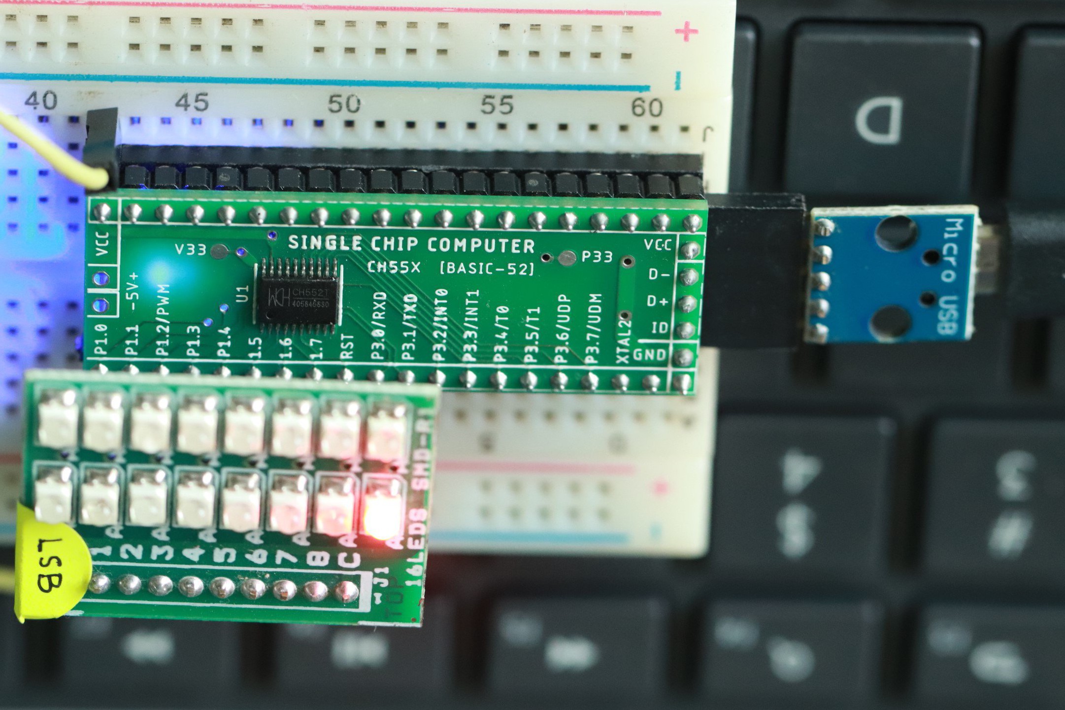
8 LEDs connected to PORT1 pins P1.0~P1.7. Left LED is P1.0 and right most LED is P1.7 or MSB of the 8 bit port.
RUNNING LED:
We can connect 8 LEDs into PORT1.0~PORT1.7 and run the LEDs. The source code can be found on Keil 8051 example folder.
01 REM 8 LED SHIFT
02 REM REM  LEFT AND RIGHT SHIFT
10 LED = 1
20 IF LED <= 80H THEN PORT1 = 0FFH.XOR.LED ELSE GOTO 1000
30 LED = LED * 2
35 FOR J = 0 TO 500 : NEXT J
40 GOTO 20
900 REM RIGHT SHIFT
1000 LED = 080H
1100 IF LED >= 1 THEN PORT1 = 0FFH.XOR.LED ELSE GOTO 10
1120 LED = LED/2
1130 FOR J = 0 TO 500 : NEXT J
1200 GOTO 1100
I2C BUS:
Connect SCL-P1.5 and SDA-P1.6 to PCF8574T 8 Bit I/O expander. Just Blinks alternative LEDs by sending 0x55 and 0xAA alternatively with some delay.
10     I2CSTART
20     I2CPUT (40H)
30     I2CPUT (00H)
40     FOR I=0 TO 127
50     I2CPUT (55H)
55     FOR J=0 TO 999 :  NEXT J
60     I2CPUT (0AAH)
65     FOR J=0 TO 999 :  NEXT J
66     PRINT I,
70     NEXT I
90     I2CSTOP
Counting from 0 to 255 and displaying using 8 LEDs using I2C bus I/O expander
10     I2CSTART
20     I2CPUT (40H)
30     I2CPUT (00H)
40     FOR I=0 TO 255
50     I2CPUT (I.XOR.0FFH)
55     FOR J=0 TO 1999 :  NEXT J
66     PRINT I,
70     NEXT I
75     PRINT  :  PRINT  :  PRINT
80     GOTO 40
90     I2CSTOP
The above one is the simplified example without any error or status checking. You can also use the original test program provided by
10     REM *******************************
20     REM *   I2C Communication Test    *
30     REM * (C) H.-J. Boehling 08.29.99 *
40     REM *******************************
50    ADDR=40H
60     FOR I=0 TO 255
70     PRINT I,
80     REM ===== I2C Write ===============
90     I2CSTART
100    IF DBY(18H)=0 I2CPUT (ADDR) ELSE 260
110    IF DBY(18H)=0 I2CPUT (I) ELSE 260
120    I2CSTOP
130    REM ===== I2C Read ================
140    I2CSTART
150    IF DBY(18H)=0 I2CPUT (ADDR.OR.1) ELSE 260
160    IF DBY(18H)=0 I2CGET B ELSE 260
170    PRINT B
180    I2CSTOP
190    NEXT
195    GOTO 10
200    REM ===== Wait for key ============
210   K=GET :  IF K>0 THEN 210
220    PRINT "Weiter?"
230   K=GET :  IF K=0 THEN 230
240    GOTO 60
250    REM ===== I2C Error ===============
260   STATUS=DBY(18H)
270    FOR J=1 TO 3 :  I2CSTOP  :  NEXT
280    IF STATUS.AND.2=2 THEN  PRINT "Time out error!"
290    IF STATUS.AND.4=4 THEN  PRINT "Busy error!"
300    IF STATUS.AND.8=8 THEN  PRINT "No acknowlege error!"
310    GOTO 90
We can remove all the comment lines to save space in RAM.
SFR Read/Write:
Read SFR Test
10 REM **************
20 REM * RDSFR Test *
30 REM **************
40 FOR I=80H TO 0FFH
50 RDSFR (I)A
60 PH0. I,"=",A,"  ",
70 NEXT I
Write SFR Test
10 REM **************
20 REM * WRSFR Test *
30 REM **************
40 FOR R=0 TO 0FFH
50 WRSFR (90H)R : REM Write to Port 1
60 RDSFR (90H)A : REM Read from Port 1
70 PH0. R,"=",A,"  ",
80 NEXT
Using Write SFR function we can directly access all the internal SFR area of the microcontroller. We can also set or reset any of the port pins using WRSFR function.
FM TUNER:
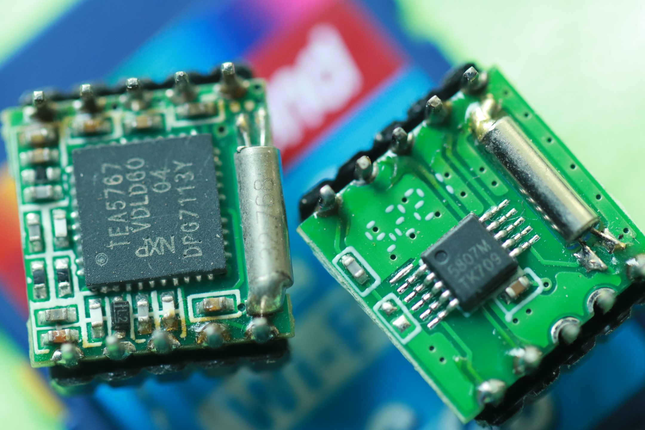
TEA5767 & RDA5807M
We can control RDA5807 using TEA5767 compatibility mode. So using a single BASIC-52 program we can either use TEA5767 or RDA5807 module or try both. It works well with both the modules.
10 INPUT "ENTER THE FREQUENCY TO TUNE : " ,FREQ
20 FREQB = 4*(FREQ*1000000+225000)/32768
30 FREQH = FREQB / 256
40 FREQL = FREQB.AND.000FFH
50 ADDR = 0C0H
60 I2CSTART
70 I2CPUT (ADDR)
80 I2CPUT (FREQH) : I2CPUT (FREQL)
90 I2CPUT (0B0H)  : I2CPUT (010H)
100 I2CPUT (00H)
110 I2CSTOP
120 PRINT : PRINT :PRINT
130 GOTO 10
140 END
The code is very simple. Please refer to the TEA5767 application notes to undersatnd the calculation. Just enter the Frequency of the channel to tune in Mega Hertz. BASIC-52 will compute the required numbers and send it over I2C bus. Hope the above program works well all over the world like Japan, Europe and USA etc.
The I2C bus address is 0x0C which is mentioned in line number 50 in the above listing.
FM TUNER:
RDA5807 Family with SEEK Tuning and VOLUME control
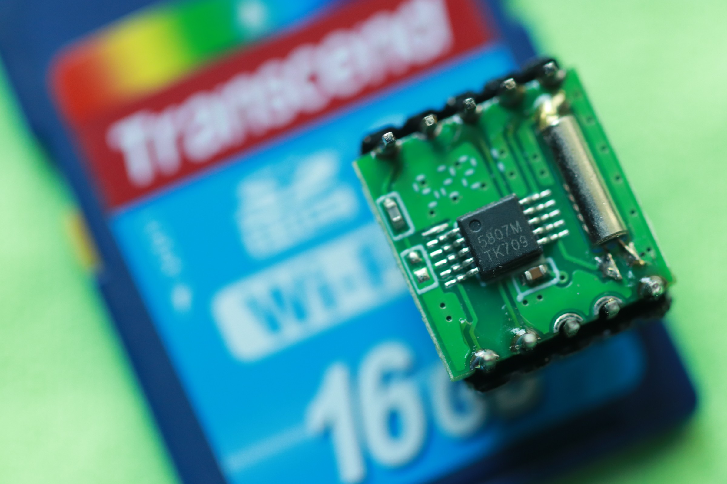
The I2C address used to address the RDA5807 will be 0x20 for sequential and 0x22 for random access. In the below program the tuner SEEK the channel UP or DOWN and capable of controlling VOLUME control in 15 steps.
REM ALL THE REM COMMENTS ARE NOT HAVING LINE NUMBER TO SAVE MEMORY
REM RDA5807M I2C STEREO FM TUNER
REM 88~108 MHz BAND
REM WITH CHANNEL AND VOLUME ADJUSTMENT
REM USE - for CH- and + for CH+
REM USE 1 for VOLUME- and 2 for VOLUME+
REM LINE# 10 DEFAULT RADIO CHANNEL FREQUENCY IN MHz
REM LINE# 20 DEFAULT RADIO TUNER VOLUME TO SET
REM LET FREQH = (FREQ*10-870)/4
REM LET FREQL = ((((FREQ*10-870).AND.3)*64).OR.010H)
10 FREQ = 91.1
20 VOLU = 1
30 I2CSTART
40 I2CPUT (20H)
50 I2CPUT (0D0H)  : I2CPUT (05H)
60 I2CPUT ((FREQ*10-870)/4) : I2CPUT ((((FREQ*10-870).AND.3)*64).OR.010H)
70 I2CPUT (08H)   : I2CPUT (00H)
80 I2CPUT (088H) : I2CPUT (0B0H.OR.VOLU)
90 I2CSTOP
100 X=GET
110 IF X= 45 THEN SEEK = 0C1H : ? VOLU," <<",CR, : GOSUB 1000
120 IF X= 61 THEN SEEK = 0C3H : ? VOLU," >>",CR, : GOSUB 1000
130 IF (X= 49).AND.(VOLU>0) THEN VOLU = VOLU-1 : GOSUB 2000
140 IF (X= 50).AND.(VOLU<15) THEN VOLU = VOLU+1 : GOSUB 2000
150 GOTO 100
200 END
1000 I2CSTART
1100 I2CPUT (20H)
1200 I2CPUT (SEEK)  : I2CPUT (01H)
1300 I2CSTOP
1400 RETURN
2000 I2CSTART
2100 I2CPUT (22H)
2200 I2CPUT (05H)
2300 I2CPUT (088H) : I2CPUT (0B0H.OR.VOLU)
2400 I2CSTOP
2500 ? VOLU, CR,
2600 RETURN
All the REM statements without line numbers will be discarded and will not occupy the target computer RAM memory.
FM TUNER:
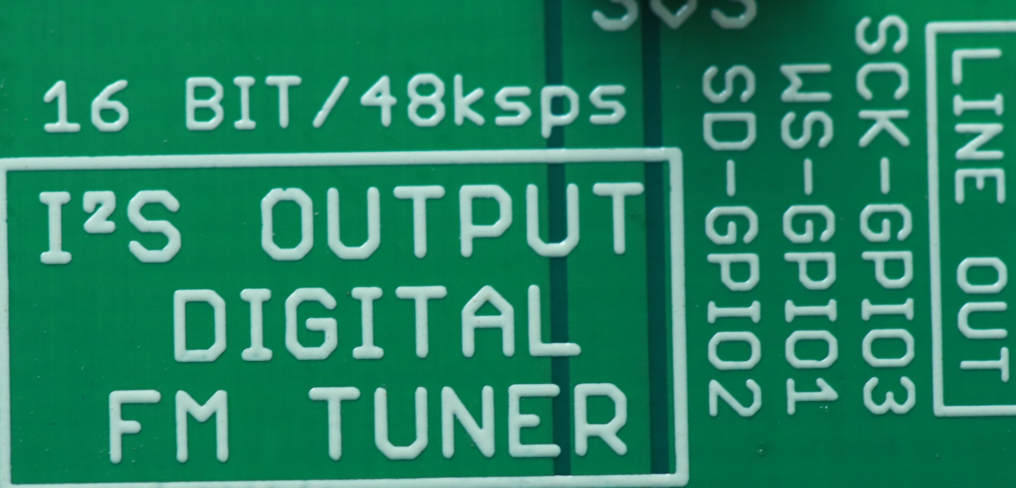
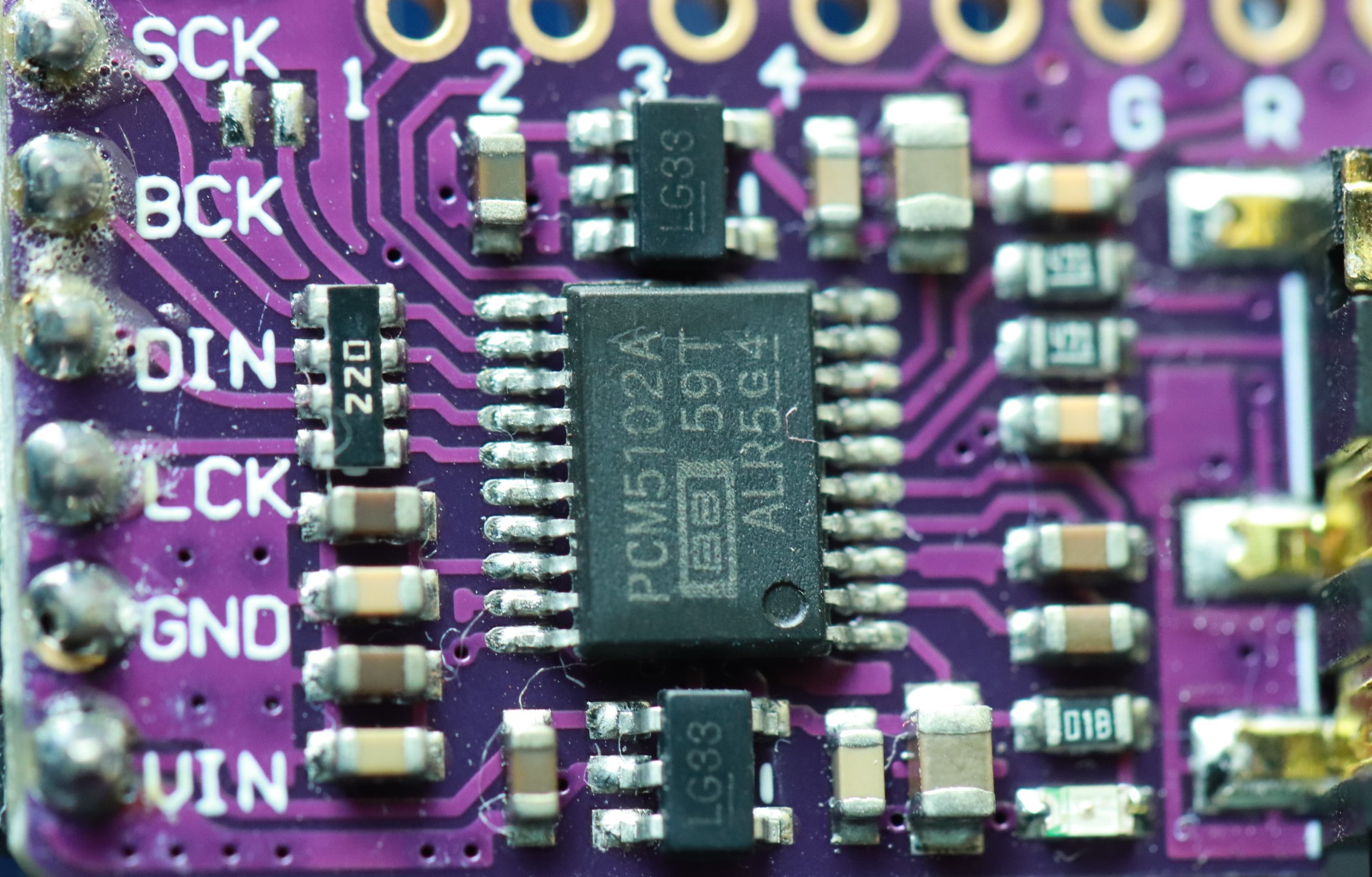
RDA7088N - SOP16
I2S Output [ 16bit signed audio at 48 kilo samples per second stereo output]
REM RDA7088 I2C FM TUNER WITH CHANNEL AND VOLUME ADJUSTMENT
REM USE - for CH- and + for CH+
REM USE 1 for VOLUME- and 2 for VOLUME+
10 FREQ = 91.9
20 VOLU = 7
30 FREQH = (FREQ*10-870)/4
40 FREQL = ((((FREQ*10-870).AND.3)*64).OR.010H)
50 I2CSTART
60 I2CPUT (20H)
70 I2CPUT (0D0H)  : I2CPUT (05H)
80 I2CPUT (FREQH) : I2CPUT (FREQL)
90 I2CPUT (08H)   : I2CPUT (00H)
100 I2CPUT (088H) : I2CPUT (0B0H.OR.(VOLU.AND.0FH))
110 I2CPUT (002H) : I2CPUT (080H)
120 I2CSTOP
130 X=GET
140 IF X= 45 THEN SEEK = 0C1H : GOSUB 1000
150 IF X= 61 THEN SEEK = 0C3H : GOSUB 1000
160 IF X= 49 THEN VOLU = VOLU-1 : GOSUB 2000
170 IF X= 50 THEN VOLU = VOLU+1 : GOSUB 2000
180 GOTO 130
200 END
1000 I2CSTART
1100 I2CPUT (20H)
1200 I2CPUT (SEEK)  : I2CPUT (01H)
1300 I2CSTOP
1400 RETURN
2000 I2CSTART
2100 I2CPUT (22H)
2200 I2CPUT (05H)
2300 I2CPUT (088H) : I2CPUT (0B0H.OR.(VOLU.AND.0FH))
2400 I2CSTOP
2500 PRINT VOLU,
2600 RETURN
16bit Singned Stereo audio output at 48 kilo samples per second digital output via SCK, WS and SD pins.
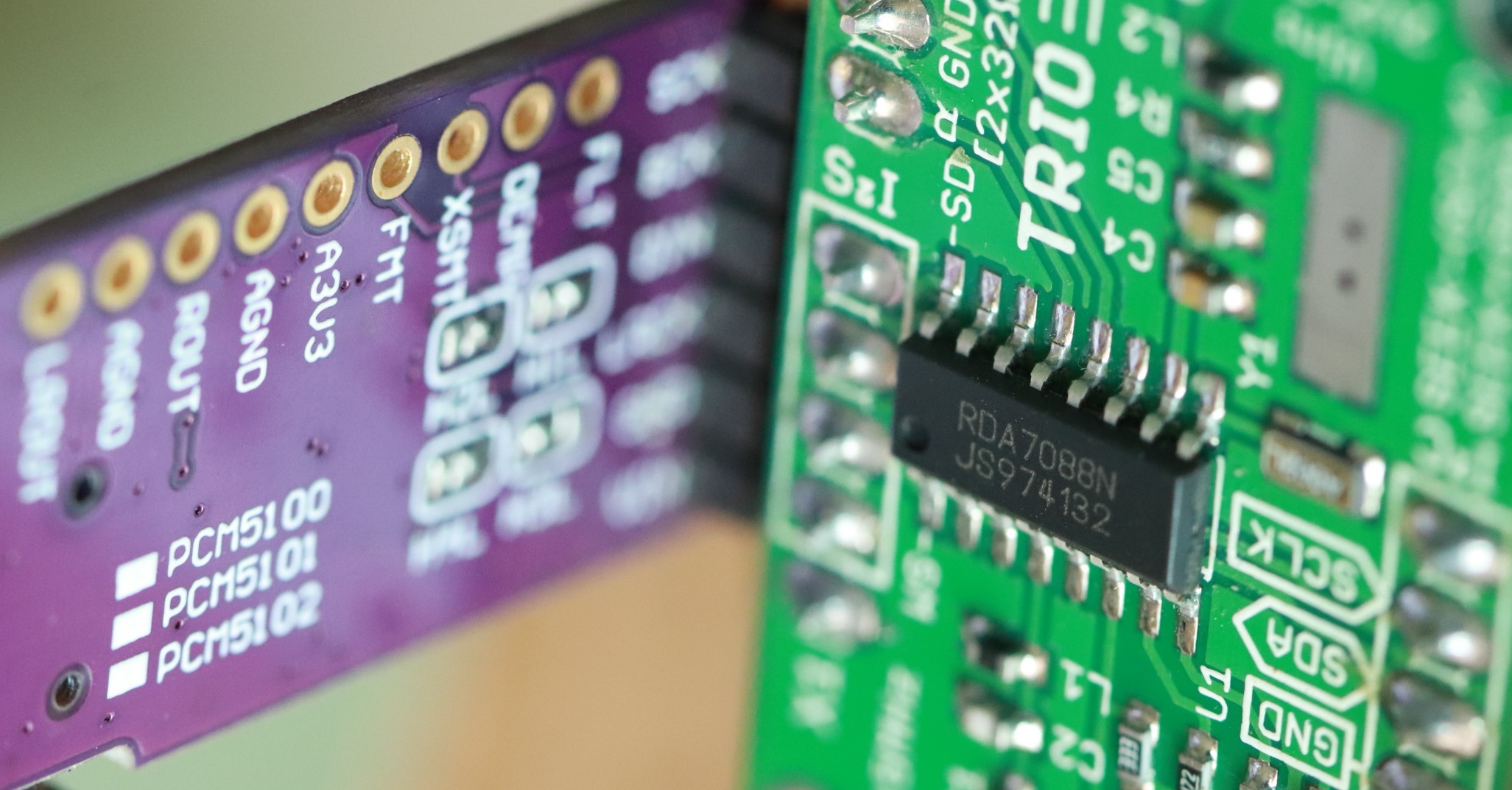
The following I2S audio DACs were tested at 16bit 48ksps configuration.
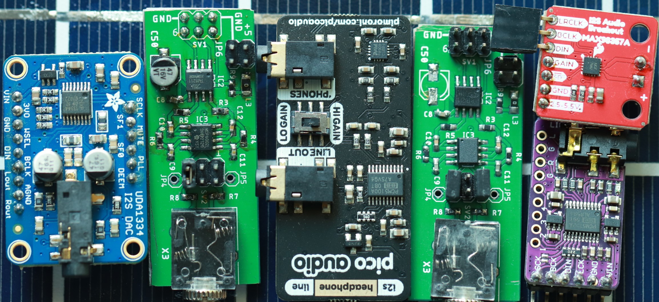
It is better to use external powered audio amplifier with volume control along with any of the I2S audio DAC.
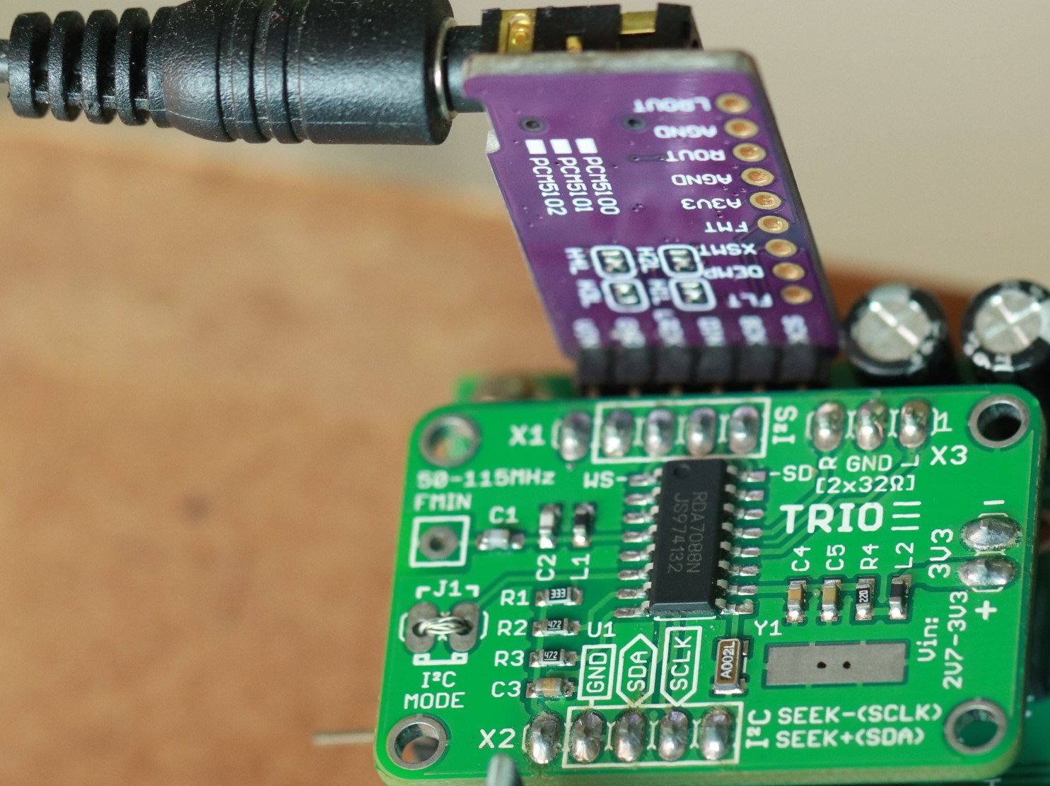
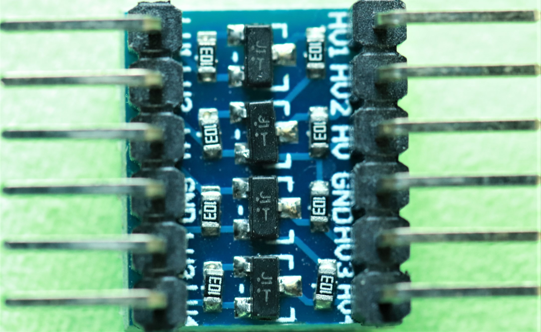
We need to have I2C bus level shifter for reliable and safer operation. Single chip computer operates at 5V and FM tuner operates around 3V. We need to connect SCL-P1.5 & SDC-P1.6 pins to FM tuner I2C bus through bi-directional two channel level shifter.
PWM at P1.2:
We can also generate Musical Notes sound using PWM function of BASIC-52 computer. The PWM output is availabe at Port1 pin P1.2. Please refer to the BASIC-52 manual for more technical details.
01 REM MUSIC
02 REM PC SPEAKER
10 FOR I=1 TO 10 :  PWM 1761,1761,100 :  PWM 1398,1398,100 :  NEXT
15 FOR I=1 TO 10 :  PWM 1000,1000,100 :  PWM 2000,2000,100 :  NEXT
20 PWM 2095,2095,300
30 FOR I=1 TO 10 :  PWM 1761,1761,100 :  PWM 1398,1398,100
40 REM K=GET :  IF K>0 THEN I=40
50 NEXT I
60 END
Since the bottom side of the board is empty, we can easily implement onboard USB-TTL circuit. So we need not to use an external USB-TTL board externaly. Just connecting USB port 5V power, GND, D+ and D- we can connect to PC/Laptop.
We can operate the single chip computer with integrated USB-TLL by just connecting 4 pins of the USB port VCC, GND, D+ & D-
It is much convenient, compact and easy way to connect to PC/Laptop or Smartphone