 Alastair Young
What is it?
A digital control knob providing 128 unique results evenly spaced around a full circle. It is designed as a control panel knob and includes a nut and washer, but can be adopted for other uses. The module communicates via the I2C bus with 16 addresses available.
This is an alternative to using a potentiometer and analog pin, allowing full-turn and multi-turn operation, and is not impacted by temperature variations. The library includes optional automatic saving of logical zero and multiturn offset to EEPROM so that the system will remember these settings after power down or reset.
Now also supported on the Raspberry Pi.
It differs from the more common incremental rotary encoder which has only two or four values in a rotation and is designed to measure full rotations and direction. This measures angles.
From the datasheet
Until now, the choice of an absolute encoder meant an expensive, and larger sized product. Through the use of combinatorial mathematics, the absolute code pattern of the Bourns® Absolute Contacting Encoder (ACE™) is placed on a single track for a very economical, energy efficient and compact product. Bourns® ACE™ provides an absolute digital output that will also retain its last position in the event of a power failure. An intelligent alternative to incremental encoders and potentiometers, the Bourns® ACE™ is ideally suited for many industrial, automotive, medical and consumer product applications.
It is, as far as I know, the smallest and cheapest gray code absolute encoder available today.
Why did you make it?
I used these to build a head-following mechanism for my Dalek dome and eye, using hand-made pcbs. I found the sensor online and say it could provide the rotational position sensing I needed, but there was no Arduino support, so I developed the code to support that.
Two were used to convert wiper motors into high powered servos

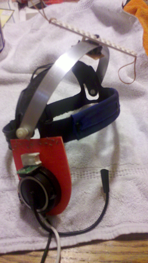
A third was used to detect the operator's head rotation in a motion control headset
A fourth is now installed in a control module and is used to enter PID tuning variables.
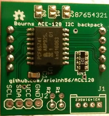
To support the ACE128 I wrote an arduino library to handle the I2C communications and gray code translation. The device itself generates gray code which has to be converted to normal numbers before use, and that takes some binary math - especially if you connect the pins in a different order from the datasheet.
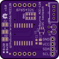
My hobby is progressing to manufactured PCBs and SMD soldering, so I pulled this design out and made some up. To my delight, the first batch all work!
What makes it special?
The ACE-128 is the smallest and cheapest absolute encoder available today. It uses some really ingenious mathematics in its design. This library and package are a unique solution for easily including digital knobs into Arduino projects.
You may prefer this to using a potentiometer and analog pin in applications where:
- temperature sensitivity of the potentiometer is causing the value to drift. As the device uses mechanical contacts it is not susceptible to environmental variations and will retain its value when powered down.
- you need full turn angular measurement
- you need multiple turns for a wider range
- you need precise control - with approx 3 degrees between positions and a very slight tactile feedback you can get the number you want without overshoot.
You may prefer this to using a rotary encoder where:
- absolute position is important (rotary encoders sense relative movement - typically full rotations and direction only)
- you need the system to remember the relative zero when powered down
- finer resolution than incremental rotary encoders (most measure 90 degree increments)
What's this doing on Hackaday?
I'm selling these on Tindie and Hackaday seems like the right place to put support documentation. I haven't used Hackaday before so we'll see how it goes.


/i/91176/products/2019-09-21T19%3A16%3A58.365Z-SAM_0730%20%282%29.JPG)
/i/91176/products/2019-09-21T19%3A16%3A58.365Z-SAM_0732%20%282%29.JPG)


 Norbert Fekete
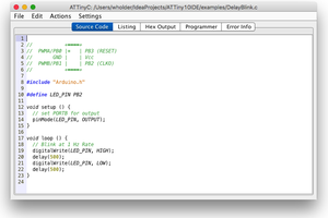
 Wayne Holder
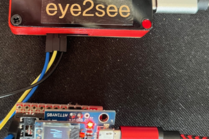
 Mark Henderson
 Ford Sleeman
Hello! Are there instructions somewhere on how to use this in true absolute encoder sense? In that If pos is at 128 or something, I turn it off and then back on, and let's say I moved the encoder in this time-frame now it's at position 200 or something, it will read 200? Is this a true absolute encoder in that sense or is it an incremental encoder that saves its last state?
To clarify - I mean move the encoder while it is off.