 electronicsworkshops
Introduction
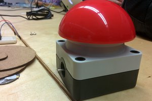
A WiFi smart button is a simple yet versatile device that leverages the capabilities of the ESP8266 (or similar modules) to connect to a WiFi network and communicate over MQTT (Message Queuing Telemetry Transport) to perform specific actions. These buttons can be used for various purposes, such as triggering smart home devices, automation, or sending notifications.
FOR FULL PROJECT :
https://electronicsworkshops.com/2024/01/30/wifi-smart-button/
Here’s an overview of the key components and functionalities of a WiFi smart button:
Components
- ESP8266 (e.g., ESP-12F): This microcontroller provides the processing power and WiFi connectivity for the smart button.
- Button: A physical button that can be pressed to initiate an action or send a command.
- Resistor: A pull-down resistor ensures that the GPIO pin connected to the button has a defined state when the button is not pressed.
- MQTT Broker: A server that manages the communication between the smart button and other MQTT-enabled devices. It facilitates the exchange of messages.
- WiFi Network: The smart button connects to a local WiFi network, allowing it to communicate with other devices on the same network.
Functionality:
- Button Press Detection: The smart button constantly monitors the state of its button. When the button is pressed, it triggers an action.
- WiFi Connection: The ESP8266 connects to a pre-configured WiFi network, allowing the smart button to be part of the local network.
- MQTT Communication: The smart button uses the MQTT protocol to communicate with an MQTT broker. It can publish messages (e.g., button pressed) and subscribe to topics to receive commands or updates.
- Action Triggering: Upon detecting a button press, the smart button can perform various actions, such as sending an MQTT message to a specific topic, triggering a smart home device, or initiating an automation sequence.
- Debouncing: To eliminate signal noise and ensure accurate button press detection, a debounce delay is often implemented in the code.
Development Steps:
- Hardware Setup: Connect the button, resistor, and ESP8266 on a breadboard, establishing the physical interface of the smart button.
- Code Development: Write code for the ESP8266 using the Arduino IDE or PlatformIO. The code includes WiFi connection setup, MQTT communication, and button press detection.
- Upload Code: Use a USB-to-Serial adapter or a dedicated programming board to upload the code to the ESP8266.
- Testing: Monitor the serial output in the Arduino IDE to ensure proper WiFi and MQTT connection. Test the button to verify that pressing it triggers the desired actions.
- Integration: Integrate the smart button into your smart home system or automation setup by configuring MQTT topics and actions on other devices.
Schematic Diagram
Schematic_IOT-Smart-Button_2024-01-30Download

PCB Diagram

3D Diagram


Order Directly from PCB WAY
I have already uploaded all these required manufacturing files in PCBWAY website. You can easily go to the below link and place you order, and get your Own Home Automation PCB manufactured from one of the best pcb manufacturer PCBWAY
Customization:
You can customize the smart button based on your specific needs. This may include adding more buttons, incorporating additional sensors, or extending its capabilities to control specific devices in your smart home ecosystem.
Overall, a WiFi smart button provides a cost-effective and flexible solution for creating custom home automation scenarios and interacting with your smart home environment.
FOR FULL PROJECT :
https://electronicsworkshops.com/2024/01/30/wifi-smart-button/

 Christoph Gerneth
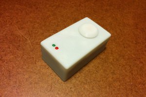
 deqing
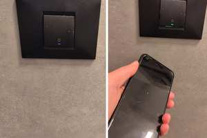
 avishorp
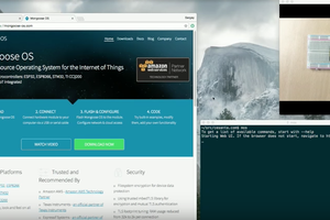
 MongooseOS
please add switch
simple 5 -8 switch setup https://en.wikipedia.org/wiki/DIP_switch
this can reprogramic button in future