 sky-guided
Since a key goal of this project is to run standalone -- no o-scope, no bench PSU, no amperage panel meter -- it's crucial to have some sort of indication of whether the circuit was in oscillation or just sitting idle.
Overall power draw reliably reflects the circuit's state. When not oscillating, there's near zero draw -- just LEDs, leakages, etc. While running the draw is more like 2-3 amps, and can be reduced down to as little as ~1.2A by lowering mosfet gate bias.
The normal approach
I had initially planned to use the pretty typical current monitoring method of a differential op-amp measuring voltage across a low value shunt resistor. Since I'm looking for a threshold current indicator rather than a continuous analog signal, the op-amp is fed into a comparator, against a reference voltage.
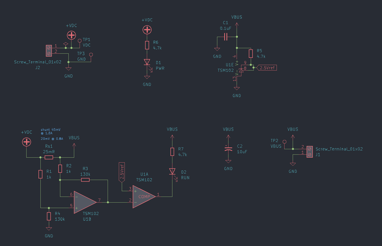
Yes, this diagram is kind of sloppy, but you won't need to linger on details here anyway. If the text is unreadable due to aliasing you can click to embiggen.
The TSM102 IC seemed like a neat combo-wombo of packaging two comparators, two op-amps, and a 2.5V reference all in one. It's also relatively inexpensive and can run off of a 40V Vcc. Purpose-built current monitor ICs also exist, but I didn't necessarily want to add a 5V regulator just for one chip, plus I thought the extra op-amp/comparator channels might also be useful for other functionality.
As mentioned in the previous project log, PCBWay sent me a sponsored board and solder stencil! Assembly was quick and easy. Thanks, PCBWay!
Well?
It didn't work.
Output voltages from the op-amp do move in response to changes in the drive power, but not in any way that's intended. I suspect that the choice of 25mΩ shunt resistor is just way too low for this application, and is getting drowned out by common-mode influences and amplifier limitations. Using 130kΩ resistors as part of the op-amp network was definitely a warning sign that things might be getting a bit too off-road. 45mV seemed an ok enough differential when I thought a 1.8A current threshold would be good, but lowering that threshold down to 800mA / 20mV certainly didn't help. (Or maybe I'm just not very good at this, and there's a fundamental design error that's gone unnoticed.)
That's all ok though, because I had a better idea.
Going Wireless
While testing out the (still-not-yet-documented) arc start module, I had to start up the main driver circuit and decided to not even hook up my scope leads for monitoring, since I figured that the primary inductor oscillation was electromagnetically noisy enough to be perceptible without a direct connection.
And that's when the inspiration hit.
Just by wrapping a clippy test lead into a li'l coil, there was more than enough inductive coupling from the primary to wirelessly light an LED. In fact, this video is of my second test of this method -- the first time I used a raw 5mm LED which burned out within a few minutes from being overdriven. (The LED shown is an "E-Cell" breadboard-friendly LED + resistor, sold by DFrobot. Super handy prototyping aid.)
This video also shows how ghostly the toroid looks with daylight filtering in through living room windows. Very different from the dimmed-room beauty shots!
IMO this monitoring method is better than a fixed yes/no threshold on current draw, since the LED brightness visibly changes in proportion to the drive intensity. It's also a much more direct measurement of what the coil is actually doing.
Feeding an inductive pickup directly into an indicator LED is either the cleverest or the most knucklehead way of solving the status monitoring problem. Probably both at the same time, really.
I can design a PCB coil trace as part of the finalized circuitboard assembly, for zero added cost. That brings the subcircuit component count from ten (including one not-recommended-for-new-designs IC) all the way down to a mere two.
Nice.
Coming next, we finally grapple with push-button arc start.
Discussions
Become a Hackaday.io Member
Create an account to leave a comment. Already have an account? Log In.
good work
Are you sure? yes | no