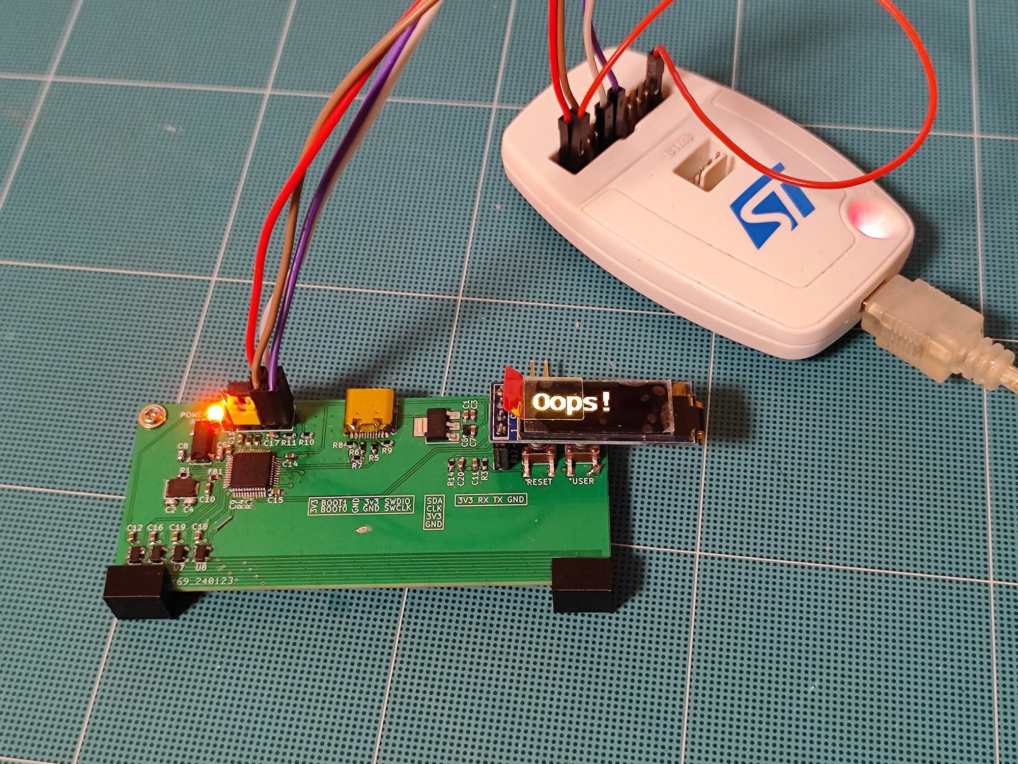
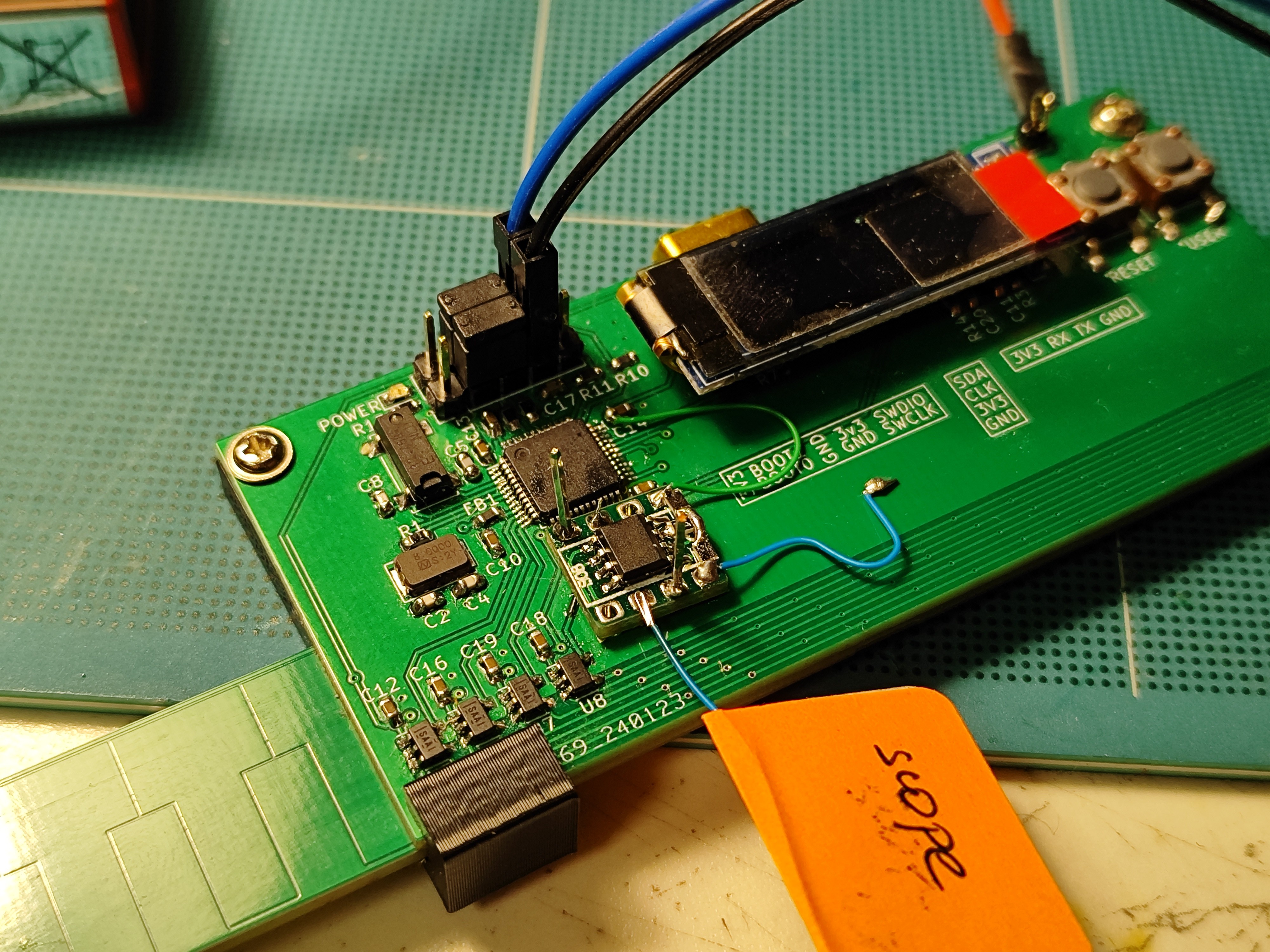
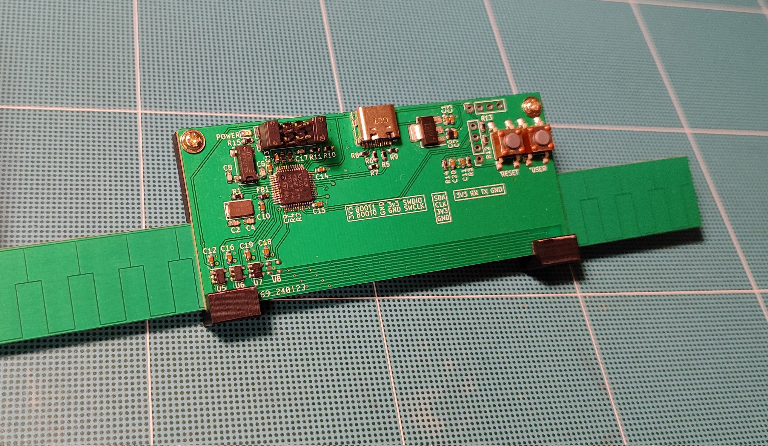
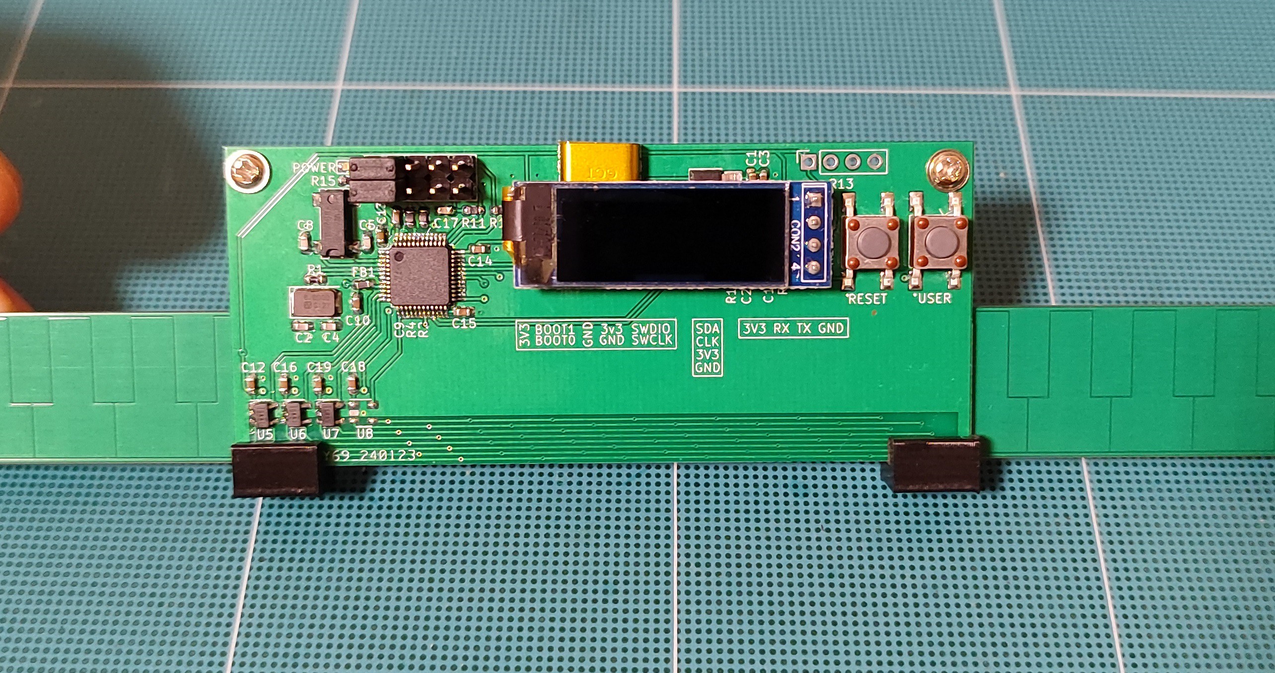
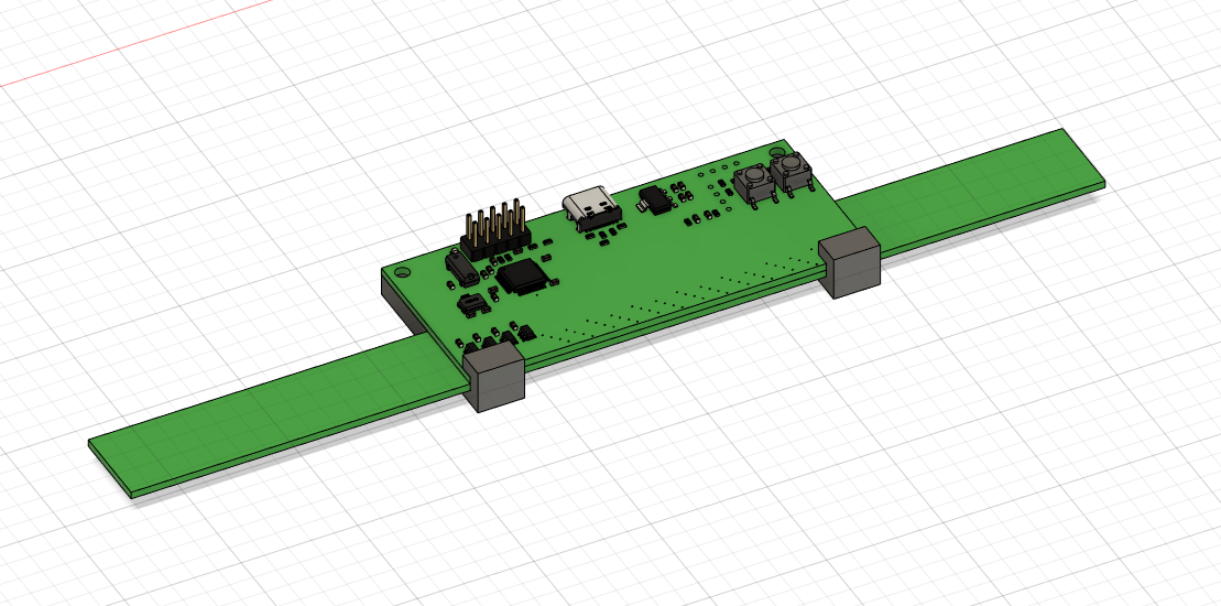
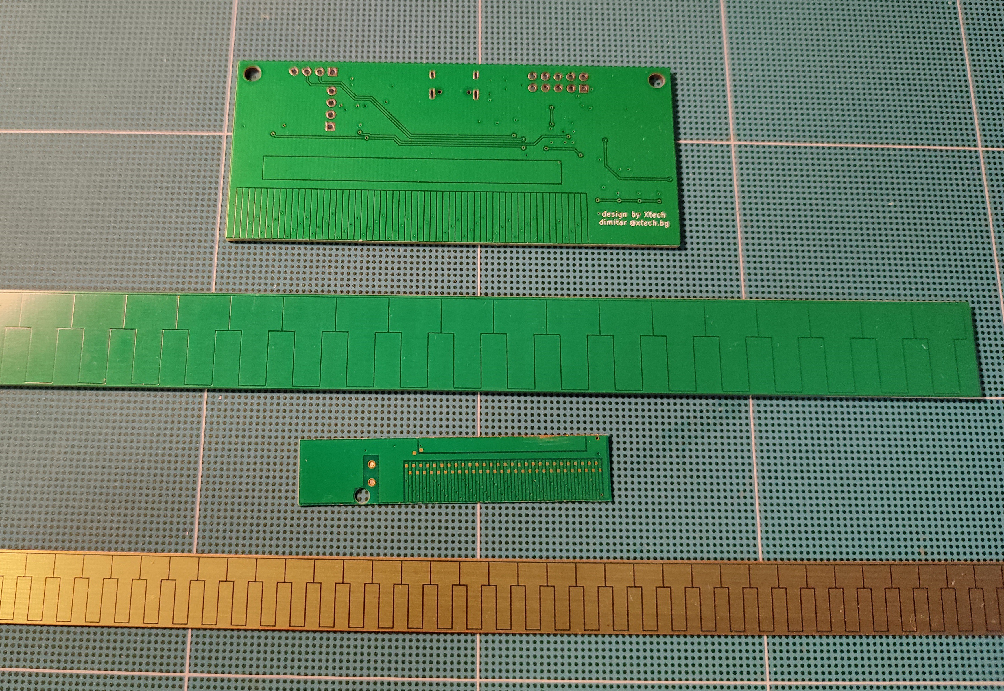
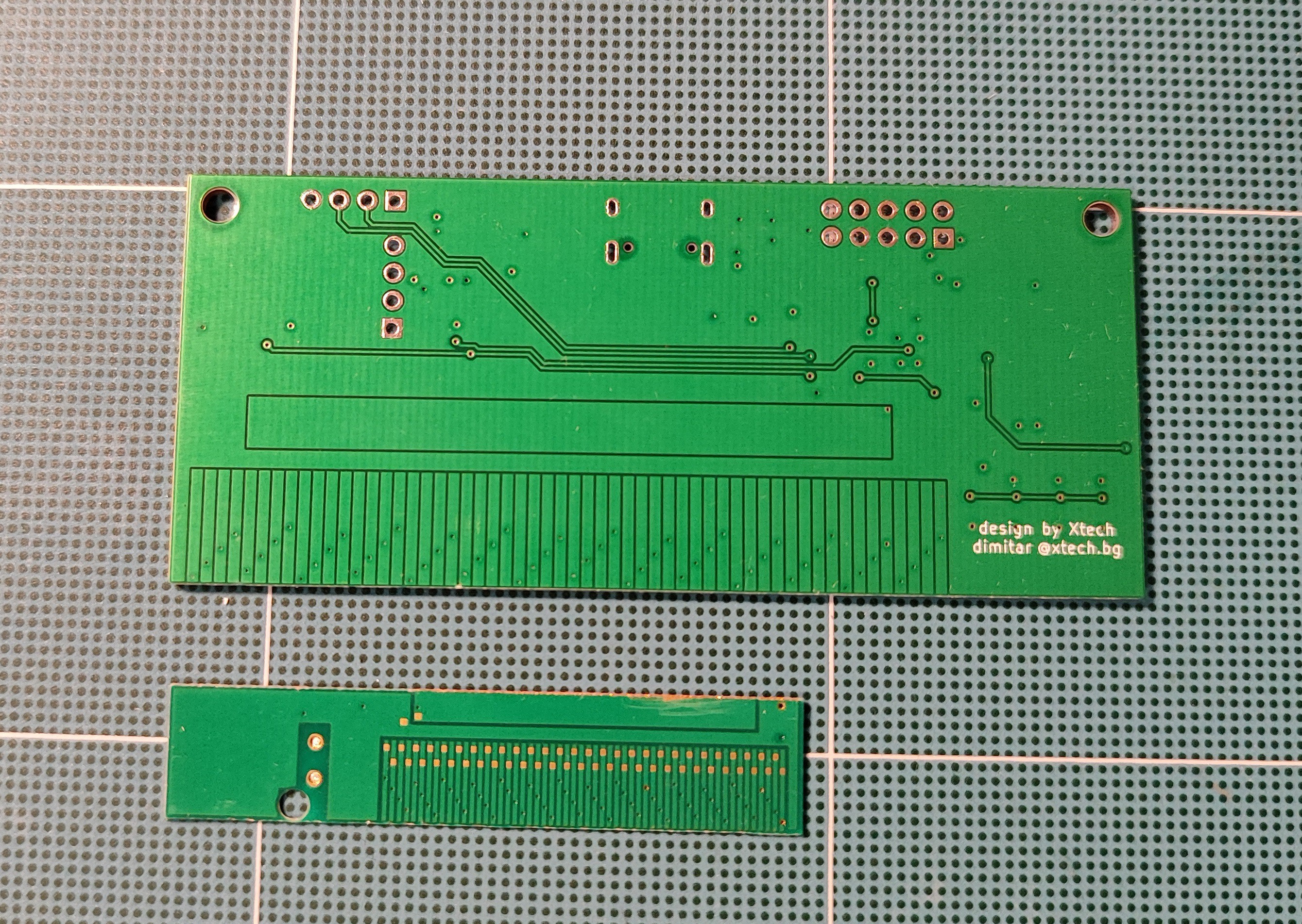
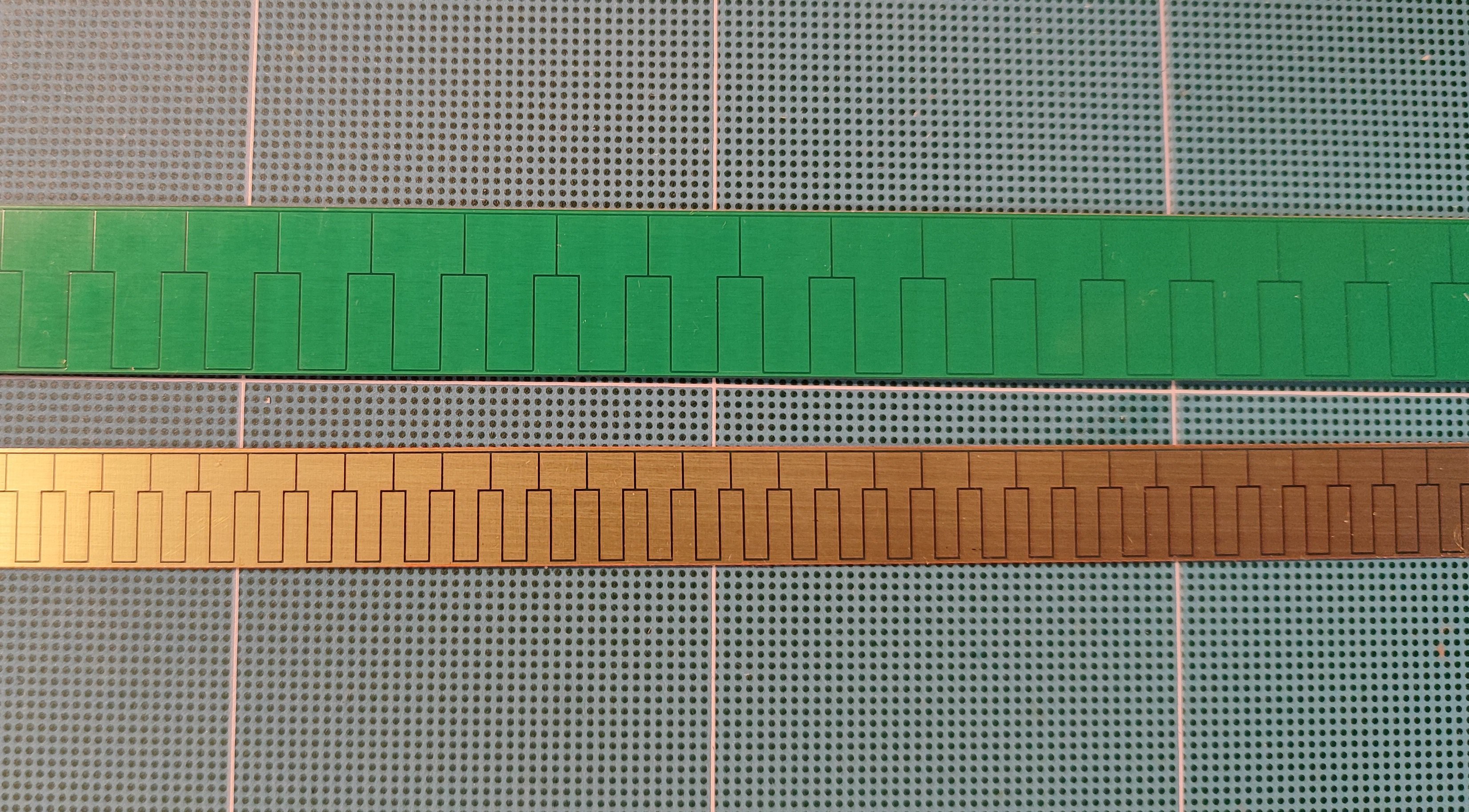
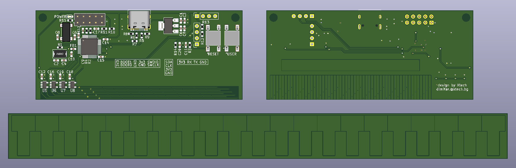
• Notes for the next version.

    Dimitar04/21/2024 at 16:45 0 comments

    Hey!

    I am waiting for some parts to arrive and in the meantime I decided to get the display running. Unfortunately I messed up the footprint and wiring was backwards. A quick work with the cutters and the soldering iron I turned the display 180° and it worked just fine! Now you can't push the buttons - but this I can fix on the v0.2 of the board.

    Shout out to afiskon for creating a lib that runs on STM32 for the SSD1306 controller. You can find the code at his git hub repo. It was a breeze integrating it!

    Cheers!
    M

  • Signal conditioning - part 1.

    Dimitar04/16/2024 at 11:13 0 comments

    Hello all,

    I have asked for help on the electronics stack exchange on what would be the best approach for the measurement of the resulting signal would be and also to solve the mystery of the negative voltage. I was given a task to make buffer so that a proper snapshot of the signal could be taken. This is the schema:

    And this is how it looked on the board, some "mad" soldering skills there :D

    And the resulting signals is as follows:

    Offset of nearly 2V

    We still have a little bit of 60Hz oscillation in there, but nothing too bad I guess.

    And now we wait,
    Cheers

  • Mechanical stuff

    Dimitar04/12/2024 at 19:41 2 comments

    At first I was very pleased with concept I came up with

    Since I was about to hookup a scope and a debugger, I made a plan to move the scale instead of the sensor board.

    In the CAD world it worked amazing, but in real world we have an issue. The long boards are not flat at all.

    This had two side effects, it made sliding of the scale hard and "sticky". And the second and more problematic: we can't keep even gap between the plates. Since the capacitance is directedly effected by space between two electrodes the signal strength varies a lot.

    In the caliper I dissected, the T-scale PCB was very thin. At first I thought it would be because it is less material - easy to install and cheaper. Now I find that it has another reason: when it gets glued to the metal chassis it will conform to it and the gap will be maintain. 

    With mass produced digital calipers they want to bring the price down as much as possible. They would not do anything unless absolutely needed.  The fact they decided to put his two extra parts (some sort of guards), speaks a lot about the necessity to keep this gap clean and even. 

    For the prototype I still find it useful to move the t-scale, but I have to come up with an idea to maintain this gap small and constant. 

    Cheer,
    M

  • Read out of HW v0.1

    Dimitar04/11/2024 at 13:53 0 comments

    Hello all,

    I have cut the trace going from the sense pad to the ADC pin of the STM32F103 to be able to get a good reading with a scope. 

    When I aligned the T scale with the "positive" pads I get the following signal on the scope.  

    If I move to one side I get this

    and when I move it to the other I get this

    So the sine wave is being shifted from one side to the other, signals are being generated the way they are supposed to.

    This is great news! This means that we have successfully validated the footprints for our caliper. 

    Next step that (I have overlooked on HW v0.1) is signal conditioning. We will need to shift this signal up since is going to -300mV and also would be nice to add a splash of amplification. 

    On that note if someone has any suggestion how to do that, please write me a comment or drop me a message!

    Cheers!

    M

  • The real world

    Dimitar04/10/2024 at 17:21 0 comments

    Hey,

    We have seen from my previous log what the theory of operation should be. Now we will take a caliper apart and see that signals are actually generated and take some measurements. 

    I took this snapshot with my scope. We can see that the pattern repeats every 1.98ms and one pulse takes 60uS

    From first glance we could assume that this is PWM and in a sense it is, but its not the one we have seen while driving LEDs for example. Lets look the steps one by one and describe them. 

    1. All of the 60uS are HIGH, we have only one step like this in the beginning.

    2. 15uS HIGH, then 15uS LOW and the rest 30uS are HIGH, this step repeats twice .

    3. First half i.e. 30uS is LOW and the rest is HIGH, this repeats 13 times.

    4. 45uS is LOW and only 15 HIGH, only once. 

    5. All 60uS are spent LOW, once in the middle.

    6. 15uS LOW 15us HIGH and the rest 30uS are low, this repeats twice.

    7. 30uS HIGH 30uS LOW, this repeats 12 times.

    8. 45uS HIGH and 15uS LOW just once in the end of the pattern. 

    Of course we have a complimentary signal that is the opposite.

    I don't have any ideas how I could 4 signals like this shifted 90 deg of each other using the timers on the STM32F103, so the best approach for me would be to do it with bit banging since all of the pins are connected to one port. 

    Next step is to reproduce this pattern on my own hardware!

    Cheers,
    M.

  • A bit more theory

    Dimitar04/06/2024 at 12:34 0 comments

    Hey,

    I write this post, so that people smarter than me can take a look and double check my assumptions. But I will start from the very beginning, so that everyone no matter your level of expertise can follow as well.  

    First we need to know how does quadrature encoding work. 

    To make our encoder work we need two things direction and impulse count. To get these we use two signals. We can count pulses either on A or B. To determine direction we just see which of the two signals goes high first A or B.

    CW

    or CCW

    More or less we do the same thing with out calipers but with sine waves and we get to have a bit more precision. 

    In the patent the T-scale is called "stationary part" and the part that holds the MCU is called "displaceable part" or "sensing part".

    Lets take a look at the "displaceable part". On the bottom are located a set of pads. The signals on the first 8 pads repeats along the pattern from left to right. See animation bellow.

    To make my life a bit easier the explanation will be given with group of 6 pads instead of 8 but the principal remains the same.

    Note: the drawing are made using this web site https://www.geogebra.org/

    Using PWM a sine wave is generated on each of the pads. We can further split out group of 6 into two, positive and negative sub groups. Inside each group the sine wave's period is shifted by 85°. The sine wave of the first negative pad is shifted 180° compared to the sine wave of the first pad of the positive sub group. In effect they cancel each other out. The same is valid for the second and the third pads in the sub groups. 

    The adder that you see is a pad located on the "stationary part". It is the bottom part of the "T" that forms the T-scale. This pad couples with the pads underneath it in effect adding the signals together. You can see the resulting sinewave with the dotted red line. 

    So the question is what happens when we move the adder pad to the right. 

    The adders starts to pick up the inverse sine wave of the orange pad. Since the positive and negative orange pads cancel each other out, the orange sine wave gets "squished". The resulting sine wave in the dotted red line gets shifted to the right. 

    If we assume that the center point is where the "adder" is only on top of positive pads, we can determine its shift by the change of phase of the resulting signal. Also the amount of phase shift can tell us the distance the "sensing part" has moved.

    This is the basics. But now a few other questions remain:

    •  How to zero the caliper?
    •  How to calibrate it?

  • First prototype is ready!

    Dimitar02/14/2024 at 19:34 0 comments

    Hello all,

    I got the first board assembled! Everything seems to come together really nicely. I am missing one differential driver, but I will get another one soon. Let the coding begin!

    With a display it looks even better!

  • 3D models

    Dimitar02/12/2024 at 19:00 0 comments

    I have uploaded 3D models of the board and t-scale here. Also I added a model of a clip to hold the whole thing together, so it is easier to operate.

  • PCBs are here!

    Dimitar02/12/2024 at 15:19 0 comments

    You can see that my board is quite bigger. Not to brag or anything... Everything seems to be up to scale. Waiting for the parts to arrive.

  • Design

    Dimitar02/10/2024 at 19:56 0 comments

    From the image above you can see the front, the back and the t-scale for my caliper. Bellow I will list a few things I considered while making this design. 

    • I chose the STM32F103 used in the blue pill because it is capable, cheap and schematic is available. People love it. Hopefully I could get help with the code if needed. 
    • I made the MCU board with 2 layer PCB, the t-scale is single layer board. I did not want to make the paths and vias small. Since I knew the proportions I decided to make everything larger than the one you will find in a store both caliper. All of this will make the board cheap to manufacture. A set is $2.25 with shipment from China.
    • It is populate on one side and the components are fairly large. I decide not to get a stencil. The component count is small and the size of the them is relatively large. I think I will get away with manually applying the solder paste. I don't get paid for this projects, so cheap as possible is the name of the game. 
    • The through hole components are located on the top side of the board, so they don't interfere with the scale moving. Two holes are present for mounting.
    • The 2x5 pin horizontal connector is for boot select, power and debugging. 
    • The 4 pin horizontal connector is an UART with power. If someone wants to implement a text based protocol for communication. 
    • The 4 pin vertical connector is made for a OLED 0.91" display (i2c). It should cover the central part of the PCB.
    • USB 2.0 full speed with USB C connector for good measure.
    • Two buttons, reset and a user button.
    • Last but not least a power indicating LED. I always regret not putting a LED that indicates if my board is power or not.

    Here are some links: schematics, BOM, footprints, gerbers.