 Dimitar
Hey,
I write this post, so that people smarter than me can take a look and double check my assumptions. But I will start from the very beginning, so that everyone no matter your level of expertise can follow as well.
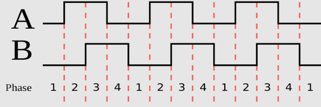
First we need to know how does quadrature encoding work.
To make our encoder work we need two things direction and impulse count. To get these we use two signals. We can count pulses either on A or B. To determine direction we just see which of the two signals goes high first A or B.
CW
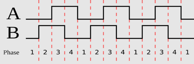
or CCW
More or less we do the same thing with out calipers but with sine waves and we get to have a bit more precision.
In the patent the T-scale is called "stationary part" and the part that holds the MCU is called "displaceable part" or "sensing part".
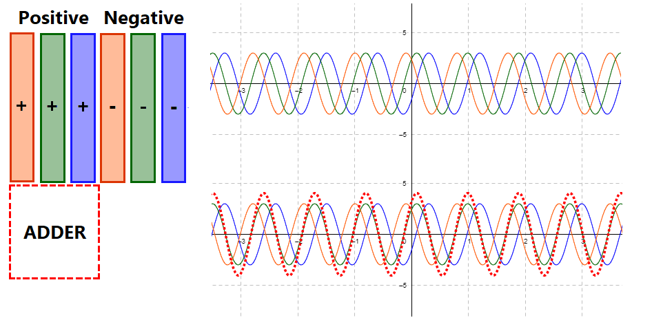
Lets take a look at the "displaceable part". On the bottom are located a set of pads. The signals on the first 8 pads repeats along the pattern from left to right. See animation bellow.

To make my life a bit easier the explanation will be given with group of 6 pads instead of 8 but the principal remains the same.
Note: the drawing are made using this web site https://www.geogebra.org/
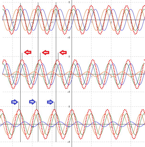
Using PWM a sine wave is generated on each of the pads. We can further split out group of 6 into two, positive and negative sub groups. Inside each group the sine wave's period is shifted by 85°. The sine wave of the first negative pad is shifted 180° compared to the sine wave of the first pad of the positive sub group. In effect they cancel each other out. The same is valid for the second and the third pads in the sub groups.
The adder that you see is a pad located on the "stationary part". It is the bottom part of the "T" that forms the T-scale. This pad couples with the pads underneath it in effect adding the signals together. You can see the resulting sinewave with the dotted red line.
So the question is what happens when we move the adder pad to the right.
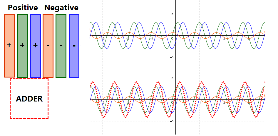
The adders starts to pick up the inverse sine wave of the orange pad. Since the positive and negative orange pads cancel each other out, the orange sine wave gets "squished". The resulting sine wave in the dotted red line gets shifted to the right.
If we assume that the center point is where the "adder" is only on top of positive pads, we can determine its shift by the change of phase of the resulting signal. Also the amount of phase shift can tell us the distance the "sensing part" has moved.
This is the basics. But now a few other questions remain:
- How to zero the caliper?
- How to calibrate it?
Discussions
Become a Hackaday.io Member
Create an account to leave a comment. Already have an account? Log In.
Are the multiple repetitions of the 8 bar pattern just to improve precision by averaging, or is there a vernier type pattern involved? Is the width of 8 bars on the sensor exactly equal to the width of one T bar on the stationary part?
Are you sure? yes | no
Hey thank you for your interest.
The multiple repetition of the 8 bars pattern improves the capacitor size. You can think of it like you have one big cap just split into bars.
The with of the bottom of the T scale is the width of 4 bars + spacing between the bars + 1 extra space.
If you look at the docs I have added on the github page you will find a university paper describing a pattern for absolute encoding of position of the slider.
Cheers,
M
Are you sure? yes | no