Bottom Line Up Front
CCTalk uses a single data-line to transmit and receive data. An interface circuit is needed before connecting with your PC’s serial port. Let’s talk about alternatives, the actual circuit and then breadboard one.
TL;DR
Directly from part 3 of the specification:
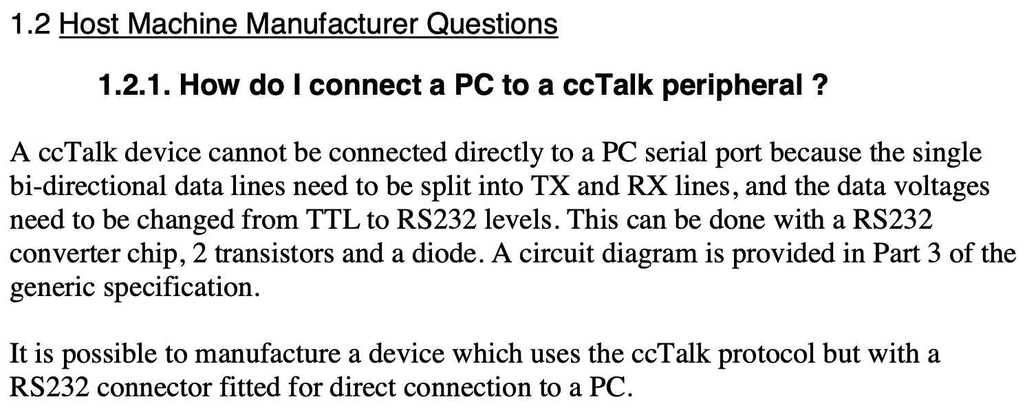
And we can graphically show where the ccTalk interface circuit goes:

Note then, that you use RealTerm (a program on your PC), a USB serial adaptor, wires for the transmit and receive wires, the circuit, another wire for the ccTalk data-line, to connect to the coin acceptor. Easy Peasy.
Ok, ccTalk uses a single wire to transmit and receive (serial) data.But, I don’t think you can just twist your serial port’s Tx and Rx lines together and then wire them onto the ccTalk data-line. That said, there’s a YouTube video that explains exactly how to do this:
I'll insert his link below.
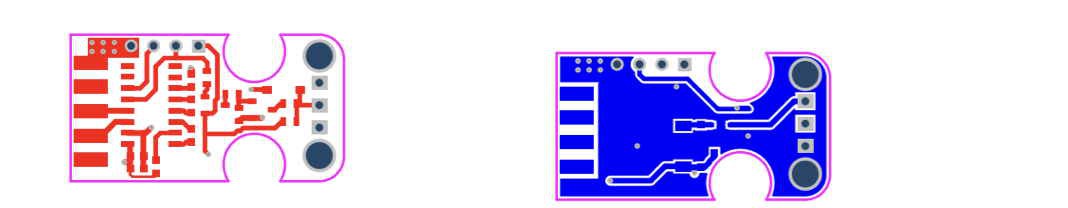
Further, there is a GitHub project to create your very own PCB. So cool, but I don’t think it’s necessary:
So between the gentleman that ties his Tx and Rx lines and a custom PCB, I prefer to follow the specification. In fact, three levels of interface circuits are provided from simple to more advanced. But really it is not that advanced (the figure is from Part 3 of the ccTalk specification):
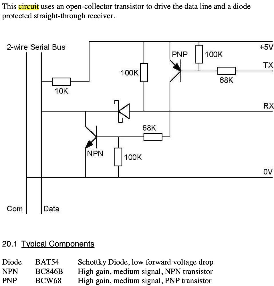
Looking at the circuit, I have the resistors, a Schottky diode, and a bunch of random NPN & PNP transistors. So let’s build this! No wait, let’s simulate the circuit first. Let’s use Falstad.
Reference the GitHub project
https://github.com/srdjanStankovic/CCtalk-converter/tree/master
Reference the YouTube video: ccTalk serial adapter
Discussions
Become a Hackaday.io Member
Create an account to leave a comment. Already have an account? Log In.