 Sagar 001
I am in the search of making a battery powered lab bench power supply, so that with a small form factor it becomes easy to carry while travelling on a project trip. This allows me to check and confirm the electronics components. But I need at least 2 lithium ion batteries in series so that I can efficiently use the buck and boost circuits in order to get a fixed high or low voltage. So, I faced many problems in design, the first one is to charge the batteries with a 12v adapter. Since it's 8.4v in series with 4.2v each li–ion battery. For this I need a charge circuit which can charge 8.4volts and 4.2 separately. Usually a battery changing circuit measures battery health, state of charge and then charge with constant current or constant voltage modes. Balance charging is also a crucial factor and plays an important role here if more than one battery is in series, but I don’t want to utilize that function here, because I am using identical cells from the same batch and manufacturer. So the internal chemical composition and charge properties are also identical in this case.
If you don’t have a balance charger and cells are identical, then the best practice of charging is to first charge the both cells separately to a constant voltage and then connect both of them in series and charge. In this way the initial voltage difference of the cells remains the same. And by chance I found an integrated circuit (TP5100) for that which can charge single and double cells (two in series). All the other battery protection, overcharge and modes are discussed below.
TP5100 Battery charger:
TP5100 is a step-down switching double 8.4V / 4.2V single lithium battery charge management chip and ideal for portable devices. Meanwhile, TP5100 built-in input overcurrent, undervoltage protection, over temperature protection, short circuit protection, battery temperature monitoring, reverse battery protection. TP5100 has a wide input voltage 5V-18V(which covers the 12v adaptor range). The battery trickle charging into pre-charge, constant current, constant-voltage three phase, pre-charge current trickle charge current is adjusted through an external resistor, the maximum charging current of 2A. TP5100 using frequency of 400kHz switching mode makes it highly efficient, and still maintains a smaller amount of heat in the large current charging.
Features:
Dual / single 8.4V / 4.2V rechargeable lithium battery
Built-in power MOSFET, a switching mode of operation
Programmable charge current, 0.1A - 2A
Programmable pre-charge current, 10% - 100>#/span###
Wide operating voltage, maximum reach 18V
LEDs for monitoring state of charge
Trickle charging mode
Modes of charging:
Let’s dive deep into the charging process and see what is happening during the changing process of a Li-ion circuit.
Trickle Charging:
Trickle charging (also known as pre-charging) occurs in two stages: It is a type of battery protection feature which is only enabled if somehow the battery gets over discharge.
Say if nominal voltage is 3.7v, and battery is over discharged (such as below 2.8V), recovery charging is performed first to prevent the battery from being damaged by excessive current. At this time, the software is not yet started, and it is a hardware-controlled behaviour. The "trickle charging" in this stage refers to the charging process after the battery is over-discharged and before it returns to the boot voltage. The current in trickle charging is 1/10 of the max charging current, which is 0.1C (If max charge current is 1A as an example, the trickle charging current is 100mA).
The commonly mentioned trickle charging refers to the charging process that continues for a period of time. It is a type of constant voltage charging and limits the value of charging current; once the battery reaches its normal voltage (3.7v), the trickle changing mode is shut down and Constant current charging mode is enabled.
Constant Current and Constant voltage charging:
During the standard charging process, the battery is charged with a constant current equal to the maximum charging current . As the battery voltage rises steadily, the charging process switches to constant voltage charging (at near about 4.15v) when the voltage approaches the set maximum voltage. At this point, the charging current gradually decreases until it reaches 1/10 of the maximum charging current, at which point the charging process ends. The constant voltage changing mode is used to keep the battery healthy and not to degrade faster.
Charge current rating is mentioned on the battery, Defined by the C rating. C is a method of representing current with respect to the nominal capacity of the battery. For example, if the capacity of the battery is 1000mAh, then 1C is equal to a charging current of 1000mA (1A).
Charge Termination:
There are two typical charging termination methods: the minimum charging current method and the timer method (or a combination of both). The minimum current method monitors the charging current during the constant voltage charging stage and terminates the charging process when the charging current decreases to between 0.02C and 0.07C. The second method starts timing when the constant voltage charging stage begins and terminates the charging process after two hours of continuous charging. In modern era, the charge termination in mobiles has not stopped even if it’s showing 100% health, at this time charging continues with a very small current to increase the overall battery life.
Most smartphones now have fast charging, where the initial charging speed is relatively fast due to a higher current. However, this results in lower battery saturation. In the later stages, low current changing is used to gradually replenish the battery to achieve higher saturation.
Circuit Diagram:
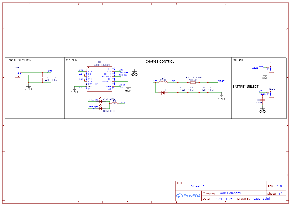
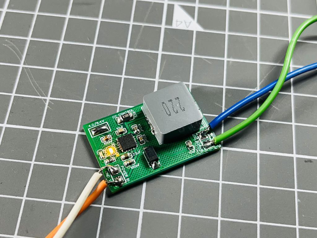
The circuit flow is given in the diagram below, buck conversion is used to charge the batteries. In this way the overall charging process become very efficient and fast. Two pins are given on the PCB to select the battery voltage 1s/2s. In the controlling circuit inductor is used to set the buck frequency and 100mOHM resistor to set the output charging current. This IC supports a max of 2A charging current at 8.4volts. Charging current depends upon the value of resistor, Table for selection current is given on the bottom silk layer of the PCB. Two Led's are used to check the battery status. And the filtration circuitry also plays an important role to reduce the power line and operating noise of the system.
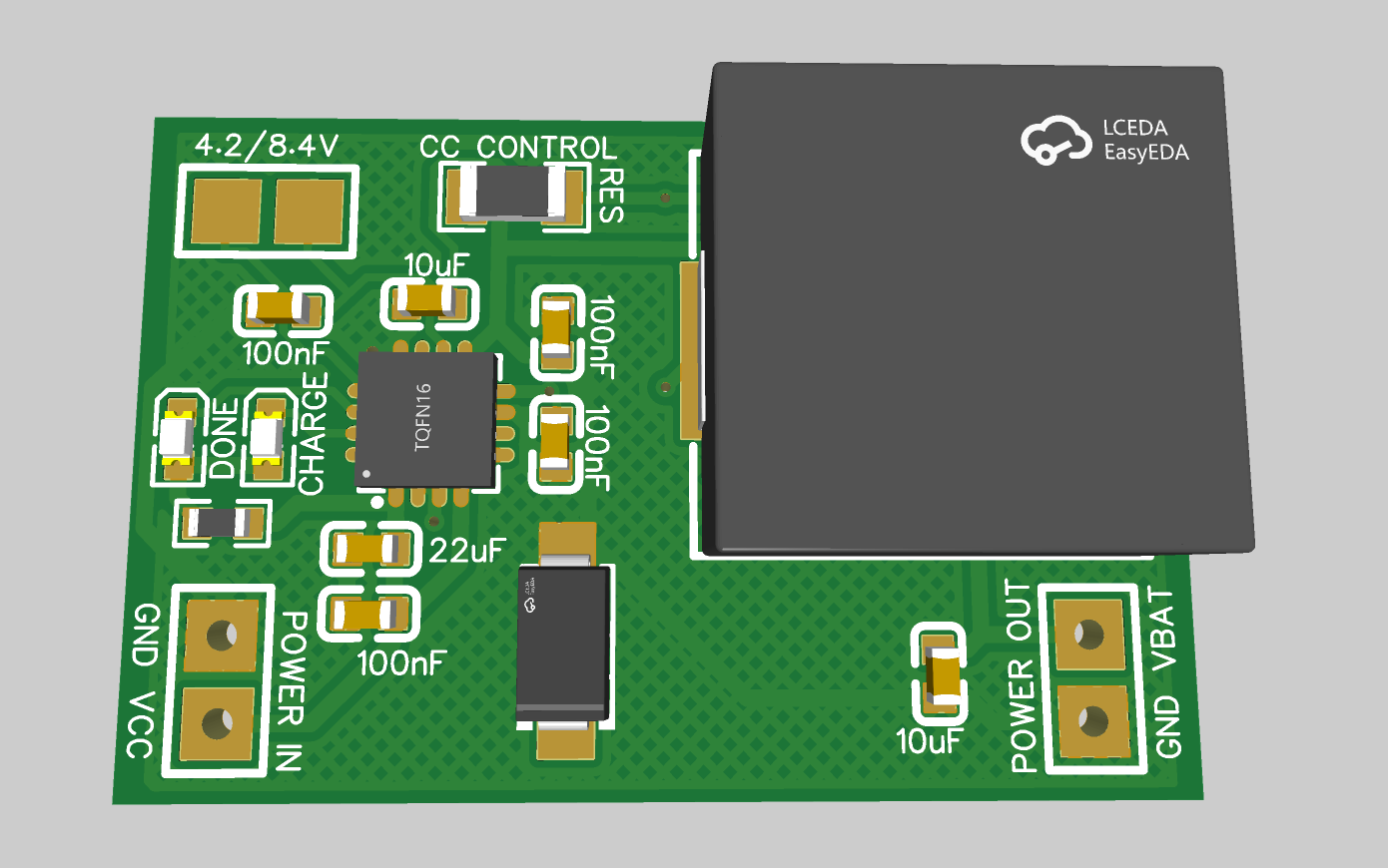
PCB design:
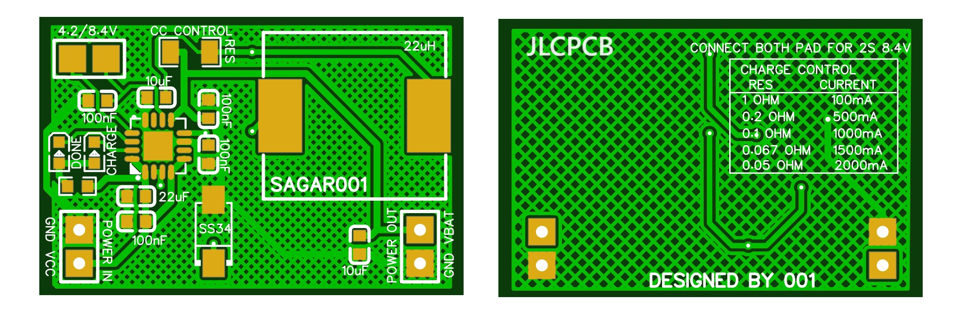
I implement the design by keeping all the noise and stabilization problems in mind. Tracks are made with enough calculations to carry max current hence delivering maximum power and reduce overall heat effects. To keep all the effects of switching section minimal on the input and output the PCB is divided according to the input to output flow. I kept the form factor as small as possible, which makes this design more practical and easier to use as a standalone battery charging device. For input and output connections Solder pads are given on the both side.
To order same PCB, download all the required files from here, I always prefer to use JLCPCB and their assembly services. JLCPCB is the China based PCB manufacture provide services in PCBA, SMT, Stencil, 3D printing and Metal parts. Sign-up now and order your first PCB, get free coupons to order PCBs from the link given here. Just upload the files and select the required board parameters, BOM and CPL files can be used to order fully assembled boards.
Assembly Instructions:
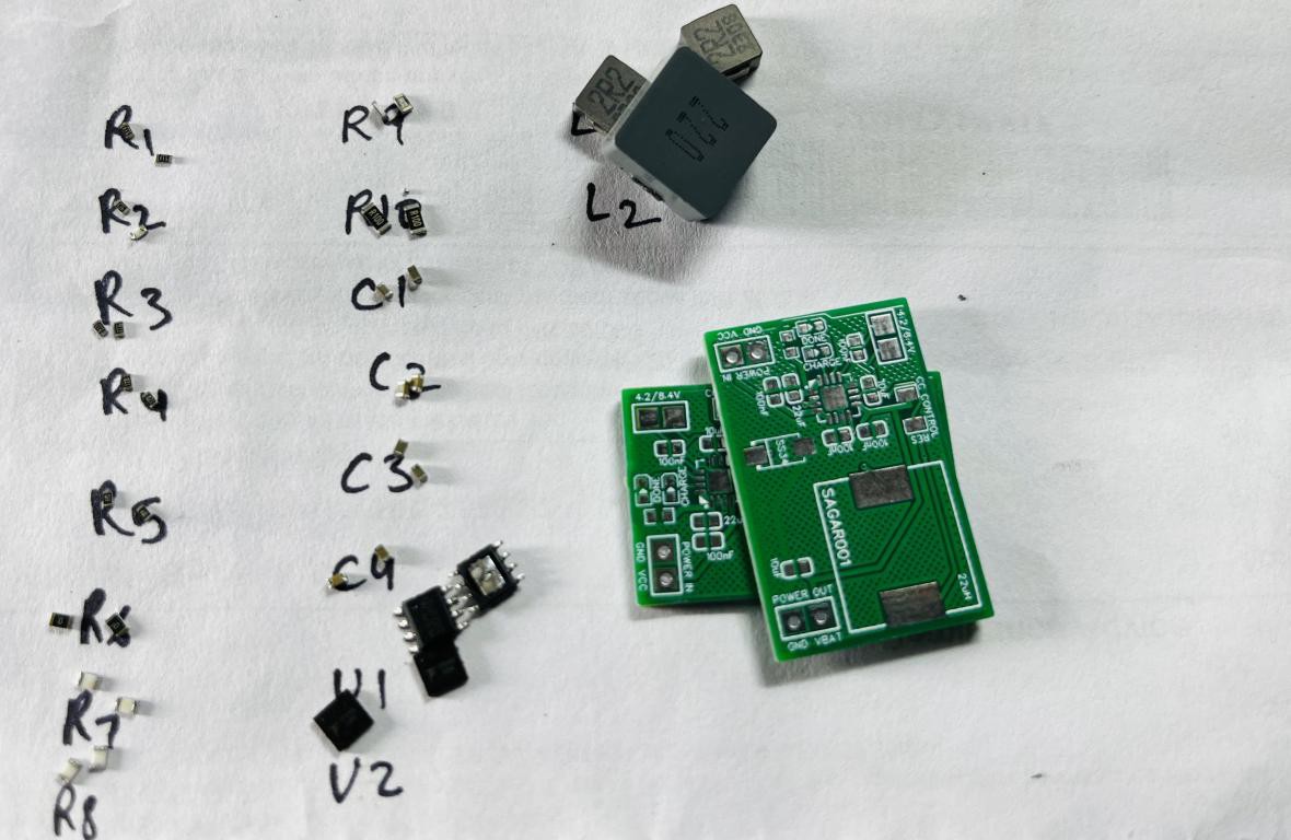
When soldering, the best practice is to mount IC first. Then small capacitors, resistor and then Inductor. Because the IC pad has lot of small pins which are very hard to solder with hand. If you don’t want to assemble the board then JLCPCB is the best to option to go with. JLCPCB is the only manufacturer offering SMT assembly services in lowest prices. And we don’t have to worry about the components, JLCPCB can source components from LCSC.
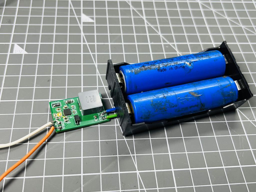
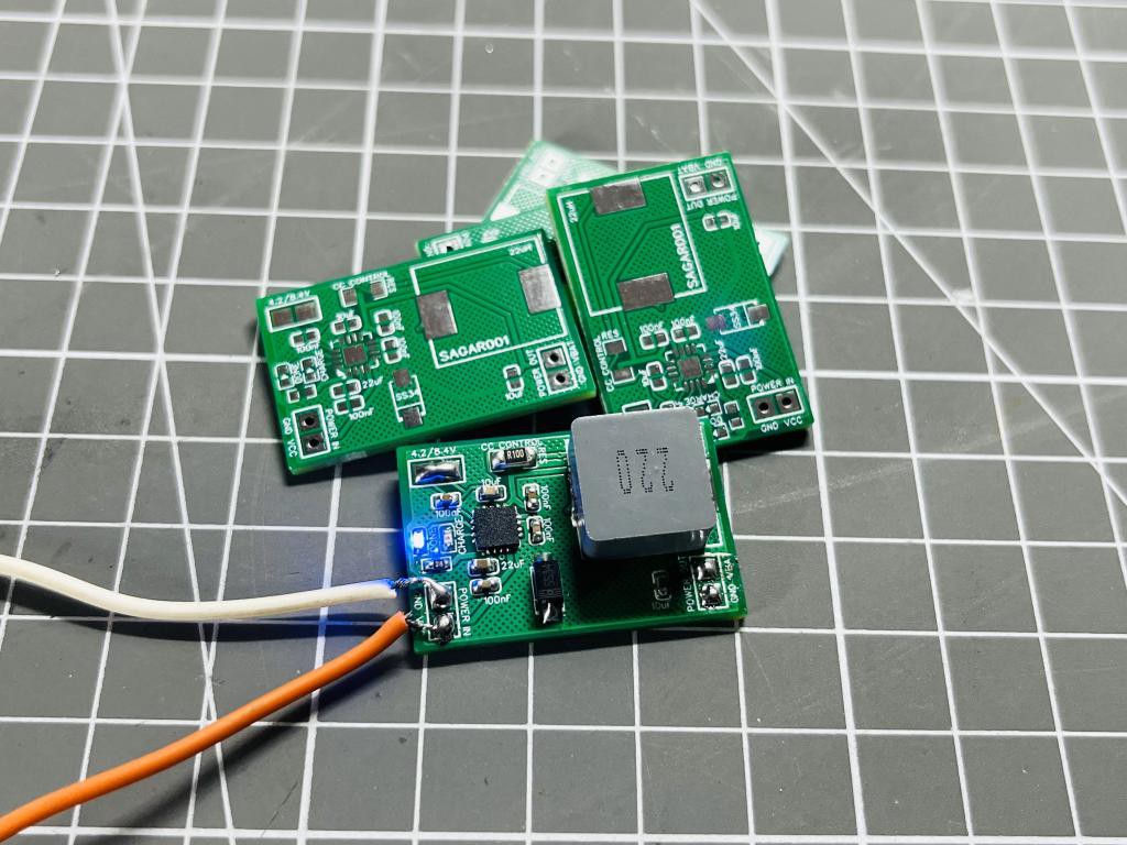
Testing:
I have done the testing with 1s and 2s battery packs, as stated earlier this for 2s operation this modules do not support balance charging. So to charge a 2S battery, two identical battery packs can be used from the same manufacturer. The results are amazing in comparison with other battery charging modules. All the protection features of the IC are tested well and in working. For a 1s battery pre-charged at 4.1v the max charging current is measured around 300mA and for 2s battery 500mA. The charging current is small because the batteries are pre-charged and in constant current mode the charging current keep reducing as charging proceeds