 Sagar 001
TP4056 is the one of the most popular modules available in very cheap prices to charge the Li-ion batteries. And to protect the batteries from overcharge, over discharge and protect the batteries by charging with constant current and constant voltage method. It has onboard MOS based different IC for protection with TP4056. The module is quite good but the IC TP4056 dissipates a lot of heat while charging. Which I think is due to linear voltage regulator section inside the IC.
Which also limits the overall charging current, because it is very over valued to add a heat sink on this module. And I think it is not the efficient way of charging nowadays. As a solution to all of this I came here with a new module based on IP2312 and designed by me keeping the max current of 3A in mind. Yes! this board comes with fast charging and protection features and all of them are listed below. You can see the PCB files given below, which can be used to order this board from JLCPCB.
IP2312:

The protection features are the most essential part while working with LI-ion cell batteries. Because any higher voltage may damage the chemical process in the battery. Which may cause the lifetime damage of the cell. But in IP2312 the scenario is better than TP4056 because here every protection feature is included in the IC, so we don’t have to use any extra IC for discharge/charge protection. And why I am focusing on this because this IC has a buck converter section rather than a linear voltage regulation. IP2312 Boost Switching Charge Converter Operating Frequency 750KHz, the maximum charging current is 3A, 5V input, 3.7V/2A conversion. The conversion efficiency is 94%; the charging current can be set through an external resistor. The input voltage of IP2312 is 5V, and the input can intelligently adjust charging current to prevent the adapter from being pulled.
- Max input voltage: 4.5 to 5.5 volt
- Trickle charging current: 100mA
- Max charging current: 3A
- Nominal Charging current: 2.1A
- Overvoltage protection: Vin > 5.6
- Undervoltage Protection: Vin < 4.5
- Standby Current: 40uA
And comes with an extra feature of Trickle charging which I have discussed in the previous article. See how a Li-ion battery charging process works from here. Trickle mode is very important to increase the overall health of battery, and it is the process of charging of battery when it is over discharged. The whole process of constant current and constant voltage can be seen in the previous article.
Features:
- Synchronous switch step-down charging
- Charging efficiency 94% (3.7V/2A)
- Maximum charging current 3A
- Charging current can be adjusted by external resistor
- Support 4.20V/4.30V/4.35V/4.4V battery
- Support charging NTC temperature protection
- Supports LED charging status indication
- Input overvoltage and undervoltage protection
- Charging timeout protection
- Over-temperature protection
Circuit Diagram:
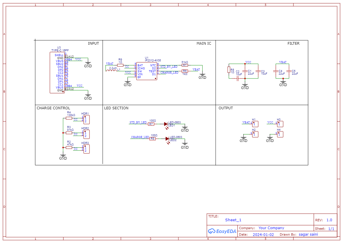
I made the hardware and circuit diagram according the battery voltage and current rating, Voltage remains constant for all here, but the charging current can be changed from the solder pads given on the back side of the PCB. By connecting the given pads to one another will set the resistor configuration to that particular current mode. And if left floating then 2A mode is selected automatically. NTC pin is given to connect a highly precise Negative temperature coefficient to monitor battery temperatures while charging, but here that function is not utilized because I am using this as a breakout board and the I have to change battery time to time. So, a good practice is to pull down that pin 51k resistor. I am also attaching the English format of datasheet, see all the design considerations once from here.
Filter section is most important part, which decides the overall noise and switching stabilization of circuit. This circuit is MOS based having parasitic capacitances at high frequency, transient parts in the supply may cause serious failure of the operation. So, at hardware the positioning and value of input/output capacitors play important role.
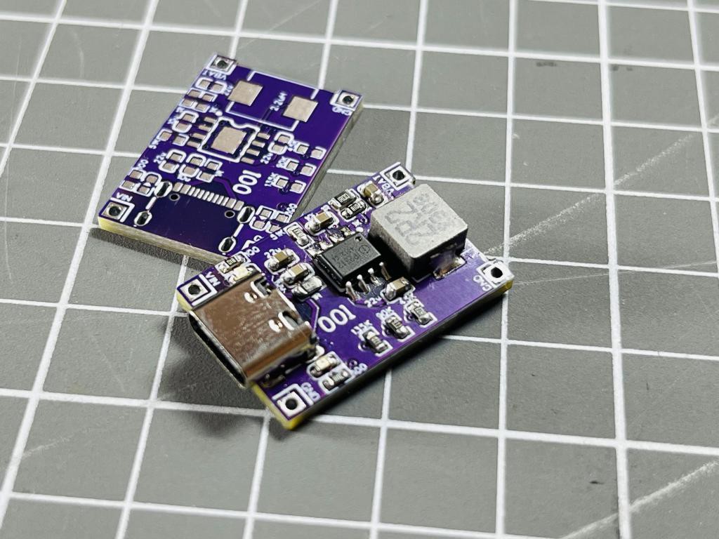
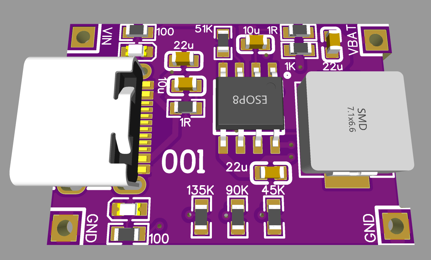
PCB files:
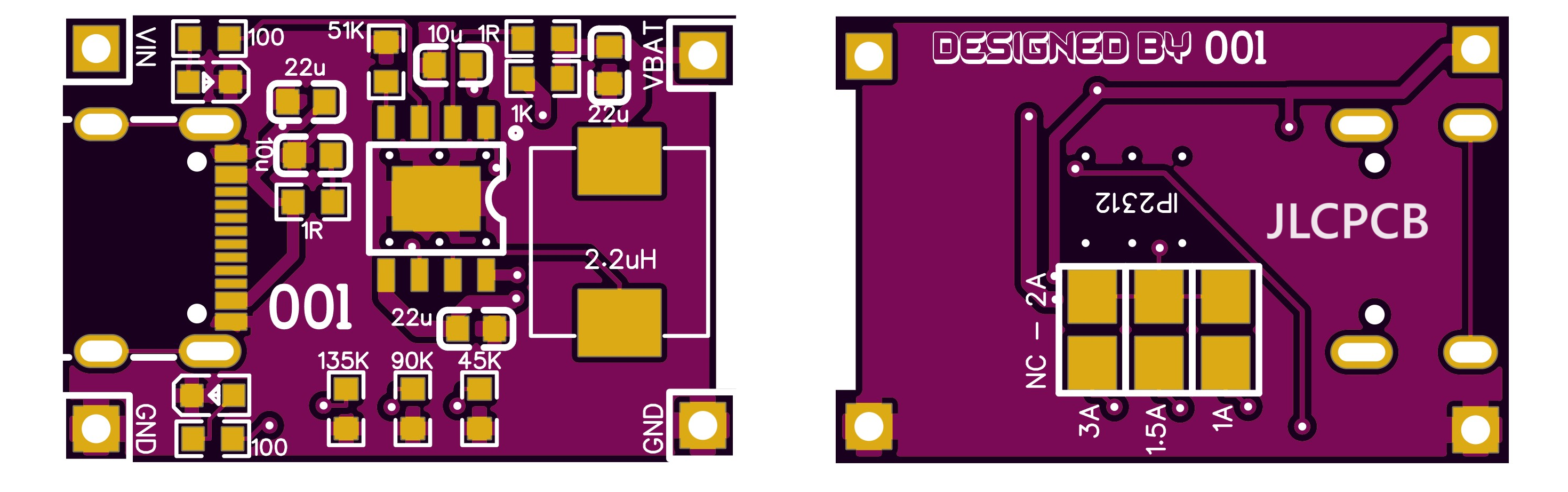
This is the Hardware level design I have implemented keeping all the noise and stabilization problems in mind. Tracks are made with enough calculations to carry max current hence delivering maximum power and reduce heat effects. Two onboard status Led’s is to monitor battery charging. And to keep all the effects of switching section minimal on the input and output the PCB is divided according to the input to output flow. I kept the form factor same as TP4056 board, which makes this design more practical and easier to use as a standalone battery charging device. For input power USB type C and solder pads are given same as TP4056 design.
To order same PCB, download all the required files from here, I always prefer to use JLCPCB and their assembly services. JLCPCB is the China based PCB manufacture provide services in PCBA, SMT, Stencil, 3D printing and Metal parts. Sign-up now and order your first PCB, get free coupons to order PCBs from the link given here. Just upload the files and select the required board parameters, BOM and CPL files can be used to order fully assembled boards.
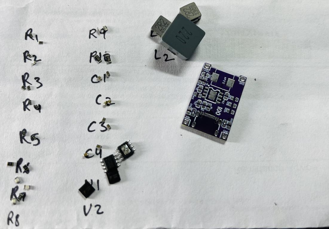
BOM and Assembly Considerations:

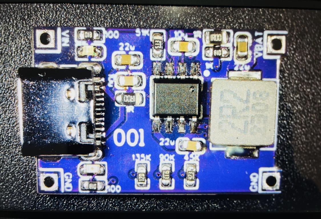
When soldering, the best practice is to mount IC and USB connector first. Then small capacitors, resistor and then Inductor. Because the IC pad and USB connector are very hard to solder with hand. If you don’t want to assemble the board then JLCPCB is the best to option to go with. JLCPCB is the only manufacturer offering SMT assembly services in lowest prices. And we don’t have to worry about the components, JLCPCB can source components from LCSC.
Testing:
I powered on the board after assembling with a power supply set to max current limit of 100mA so that if anything goes wrong, it will not damage anything. But worked in the first go, all the connections are correct, but always check the VCC and GND lines continuity before powering ON. So, I connected a 3.9V LI-ION battery having max charge voltage of 4.2V. The default charging current is set, I have not made any connection in backside given pads. The charging current rating should match the battery rating, so I always recommend to use a high C rating battery, while charging with 3A.
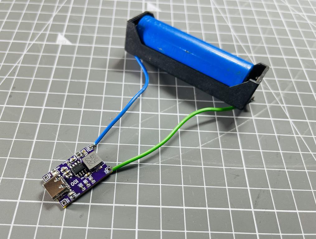
I supplied the board with my variable power supply and I noted that as battery voltage keeps on increasing the charging current reduce. So, we can say the max charging current 3A is constant for a little while when battery is fully discharge and then reduced to nominal value of 1.5-1A. See the comparison given below between TP4056 and IP2312.
When charging the battery at full potential a very little heat is produced, which satisfies the 94% efficiency of this IC. I also have tested all protection features and all of them are working very normally. It is always recommended to check the output voltage of board which should be in the range of 4.15-4.22 volts for Li-ion battery.
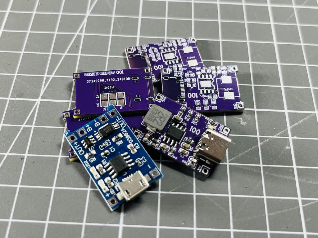
Comparison with TP4056:
I have tested both the boards with same battery one after the another, the battery is charged to 4.0 volts initially. The results are obtained to charge the same battery for 10 seconds with these boards. So, we can say battery voltage is constant in this 20 second testing period.
With TP4056 the max charging current is 450mA and with TP2312 the same battery charging current is measured nearly 1A. In all, it doubles the charging rate, increase the overall efficiency and covers almost all protection features.