 gokux
gokuxintro
Hi, in this project we are going to make a motion detection alarm with IMU 6050, it is a 3-Axis Accelerometer and Gyro Sensor module. By using this, if small movement is detected by the IMU , it will trigger a sound in the buzzer . Basically it will alert you if an object moves even if it is supposed to be stationary , like a door , home appliance ,or drawer. You can attach this device to any surface with a double tape . It is also useful for monitoring children and elderly people.

How to use it
Activation sequence
After powering on the alarm will not be activated.For activating this alarm you need to press down the push button then you will hear one beep sound which indicates the activation sequence is successful.
Stand by sequence
After pressing the button we will have 4 seconds to place this alarm , any movement happening during this 4 seconds will be ignored .
Detection sequence
After the stand by sequence you will hear two beep sounds which indicate the Detection sequence is started . From here the alarm is fully armed. Any small movements happening in 3 axis of the device will be detected and trigger this alarm continually for 10 seconds . After this alarm will be offline we need to reboot the alarm with the power switch and again go through the activation sequences.
We can customize the stand by time , alarm duration, and movement threshold (sensitivity) from the code.so let's get into it
[ product type image with info graphics]
Supplies
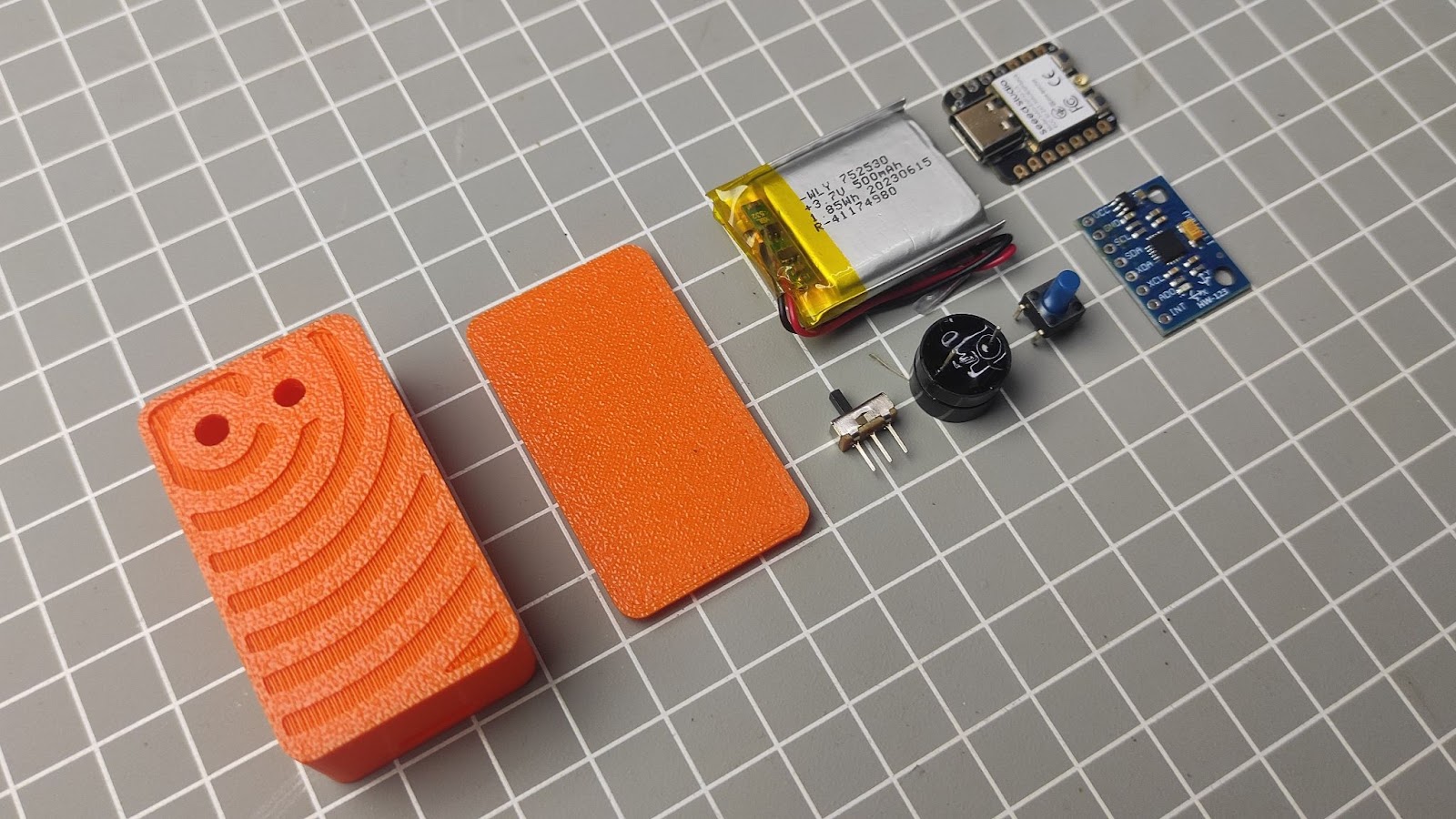
Parts
- Seeed studio xiao esp32c3
- MPU-6050 3-Axis Accelerometer and Gyro Sensor
- 500mah 3.7v battery (identical battery with 600mah)
- Slide switch
- Push switch
- Buzzer
Tools
Glue gun
Soldering iron
3d printer
Step 1 Modeling in Autodesk Fusion 360 and 3d printing
[ wire frame photo of the model ]
Used Fusion 360 to plan and design my project. The main body is designed to hold the battery and electronics without needing screws—it just snaps into place. To make sure everything stays secure, I used some hot glue. I found some accurate models of the modules online. that made the design process much easier, all design files are given below
I'm not going in depth into the design process but i will show you how i achieved this design on the front side of the 3d print
[ Details of modeling the front pattern ]
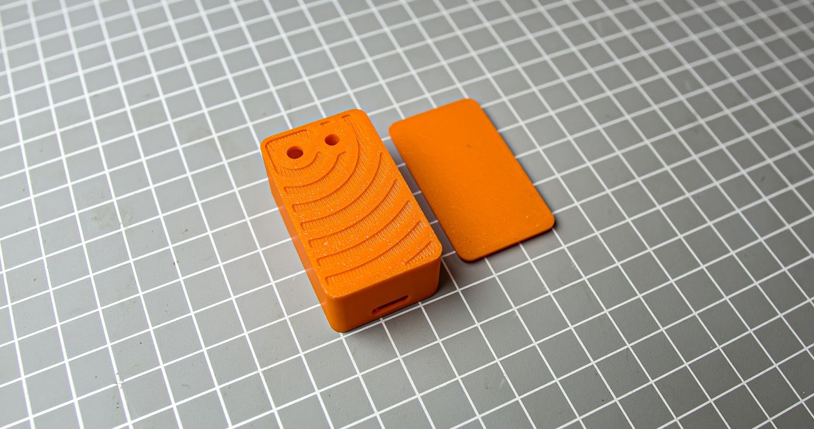
After the design i 3d printed all the parts
Step 2 Uploading Code to XIAO
I always like to upload the code to the microcontroller before assembly. Here we are using a tiny Xiao ESP32C3 from the Seeedstudio.i choose this because i have to make this device small as possible , xiao is very small version of ESP32C3 , also it has battery protection chip built-in so be we dont need external BMS on it, so we can save space in it
I am using Arduino IDE for flashing the code. Follow these tutorials for setting up IDE for XIAO ESP32C3 and learn more about this board. Make sure to install Adafruit_MPU6050.h library before compiling .
https://www.youtube.com/watch?v=qNzlytUdB_Q&t=944s
Code
#include <Wire.h>
#include <Wire.h>

#include <Adafruit_MPU6050.h>

Adafruit_MPU6050 mpu;  // Create the sensor object

const int buttonPin = 2;

const int buzzerpin = 11;

const int standbyDelay = 4000;

const int alarmDuration = 10000;

const int movementThreshold = 12;

unsigned long buttonPressTime = 0;

unsigned long activationStartTime = 0;

bool alarmActive = false;

bool inStandby = false;

void setup() {

  Serial.begin(9600);

  while (!Serial) {

    delay(10);

  }

  Serial.println("Motion detection alarm system starting...");

  pinMode(buttonPin, INPUT_PULLUP);

  pinMode(buzzerpin, OUTPUT);

}

void loop() {

  // Button press handling and activation sequence

  if (!digitalRead(buttonPin)) {

    buttonPressTime = millis();

    Serial.println("Button pressed");

  } else if (buttonPressTime > 0 && millis() - buttonPressTime >= activationTime) {

    activationStartTime = millis();

    alarmActive = true;

    inStandby = true;  // Enter standby mode

    digitalWrite(buzzerpin, HIGH);

    delay(500);

    digitalWrite(buzzerpin, LOW);

    Serial.println("Alarm activation sequence initiated");

    buttonPressTime = 0;

  }

  // Standby sequence (no sensor readings)

  if (inStandby && millis() - activationStartTime >= standbyDelay) {

    for (int i = 0; i < 2; i++) {

      digitalWrite(buzzerpin, HIGH);

      delay(250);

      digitalWrite(buzzerpin, LOW);

      delay(250);

    }

    Serial.println("Detection sequence started");

    inStandby = false;  // Exit standby mode

    // Activate MPU6050 only after standby

    if (!mpu.begin()) {

      Serial.println("Failed to find MPU6050 chip");

      while (1) {

        delay(10);

      }

    }

  }

  // Motion detection and alarm (now using sensor readings)

  if (!inStandby && alarmActive) {

    sensors_event_t a, g, temp;

    mpu.getEvent(&a, &g, &temp);  // Read sensor data

    int totalAccel = sqrt(a.acceleration.x * a.acceleration.x +

                           a.acceleration.y * a.acceleration.y +

                           a.acceleration.z * a.acceleration.z);

    Serial.print("Total acceleration: ");

    Serial.println(totalAccel);

    if (totalAccel >= movementThreshold) {

      Serial.println("Motion detected!");

      unsigned long alarmStart = millis();

      while (millis() - alarmStart <= alarmDuration) {

        digitalWrite(buzzerpin, HIGH);

        delay(500);

        digitalWrite(buzzerpin, LOW);

        delay(500);

      }

      Serial.println("Alarm stopped");

      alarmActive = false;  // Reset for next activation

    } else {

      Serial.println("No motion");

    }

  }

}
Step 3 Wiring Diagram
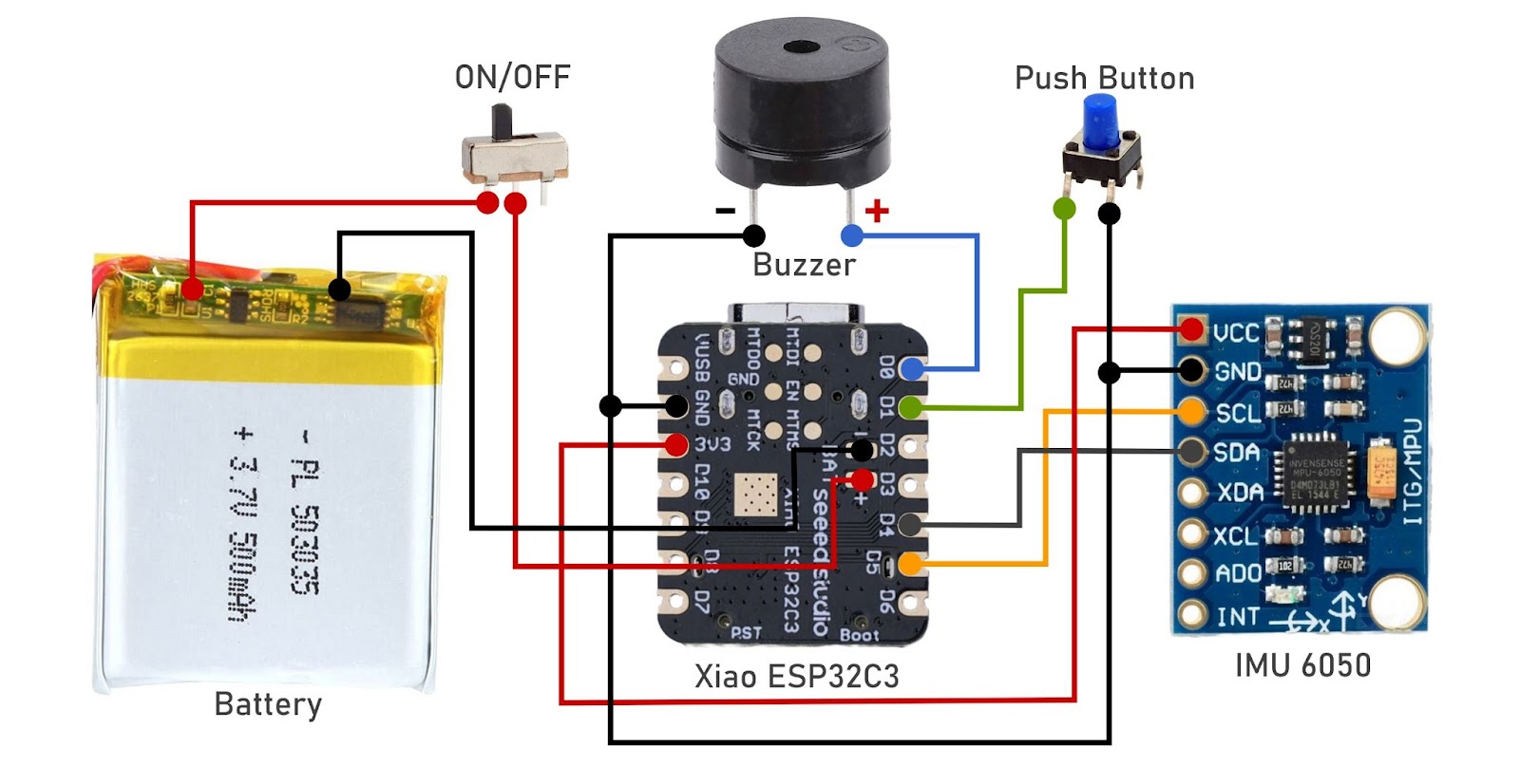
The brain of this project is xiao ESP32C3 which is paired with an IMU 6050 sensor , a small push button on D1. and a buzzer connected on the D0. We also have a slide switch for power control. Everything is powered by this 3.7v 500mah battery. Now let's look at the detailed build instructions in the next step.
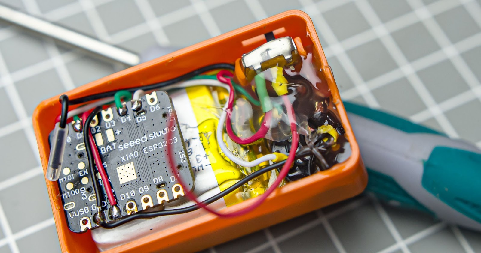
Step 4 Assembly and Wiring
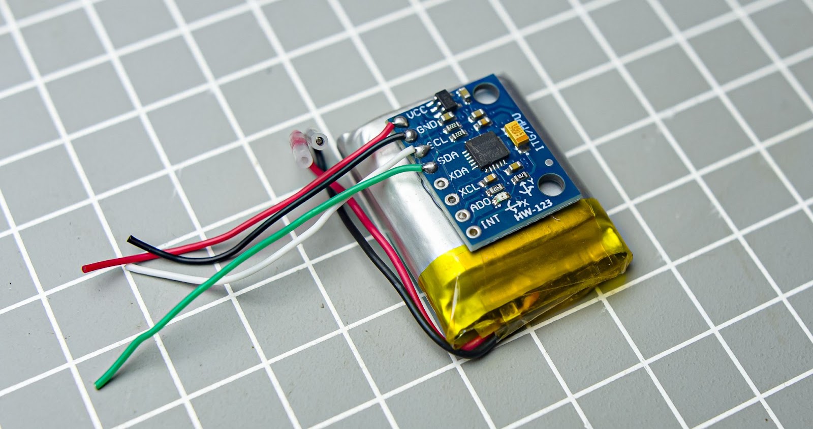
Step 1
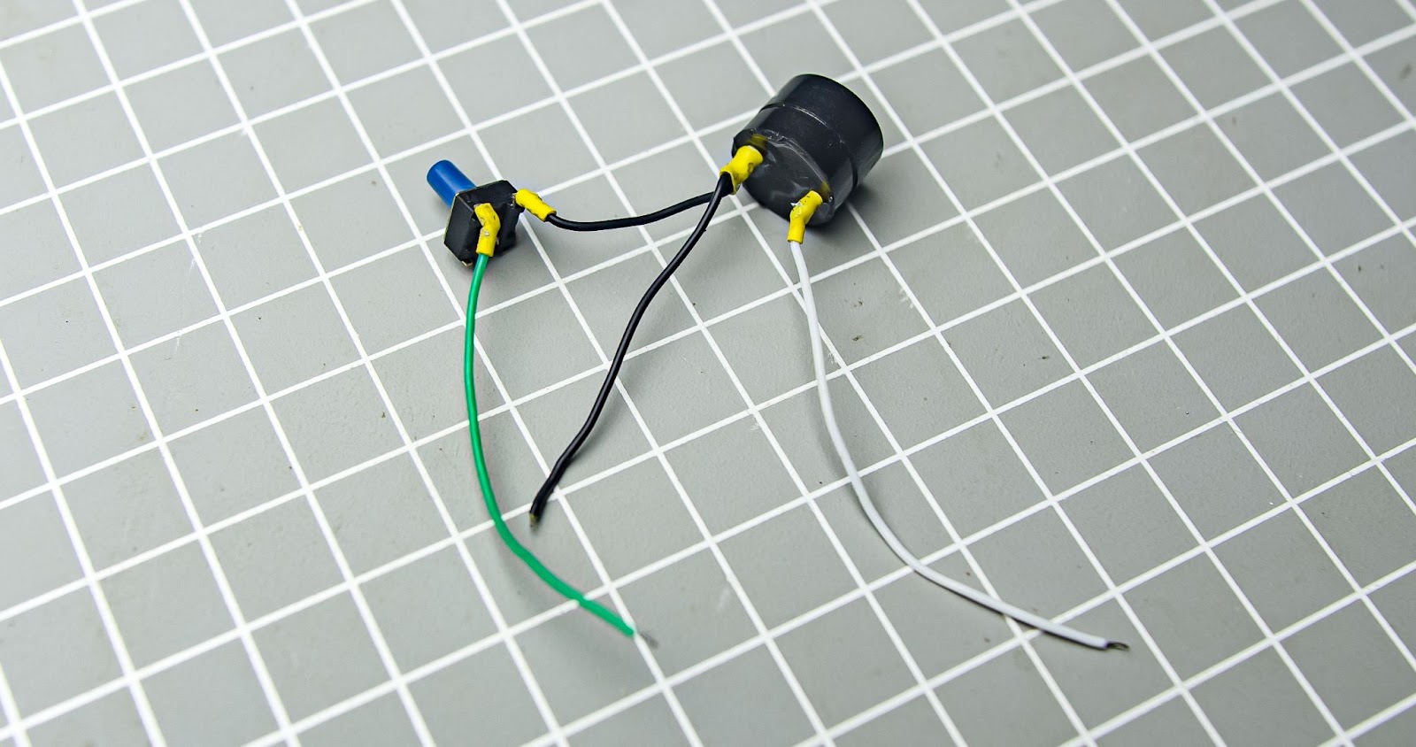
Solder 4 small wires in to the imu6050 sda scl vcc gnd also not the wire colors

Step 2
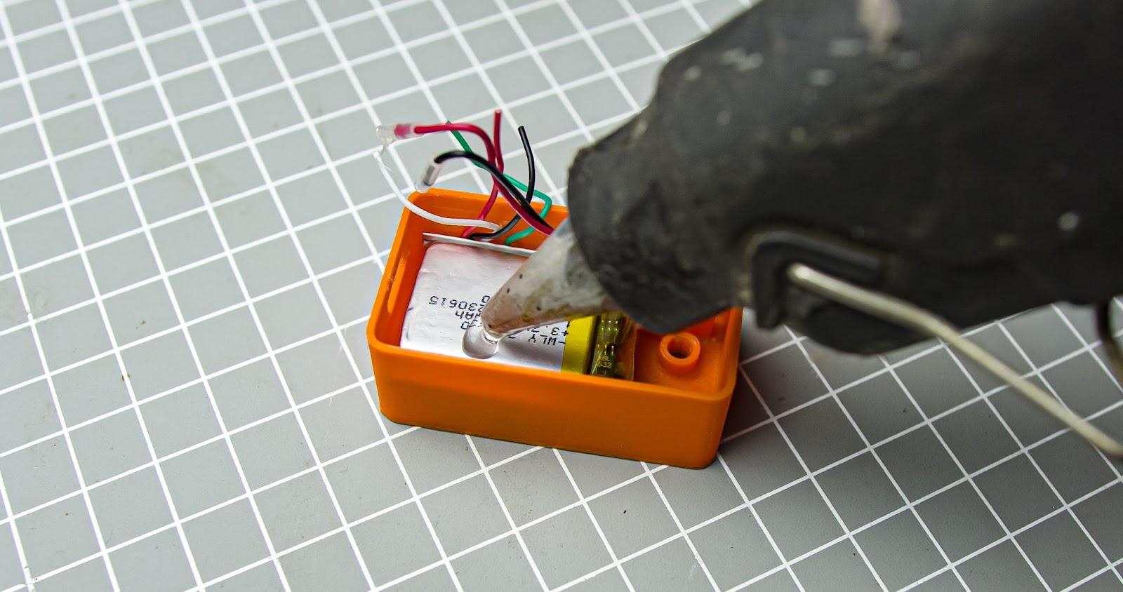
Glue the IMU in the battery
Step 3
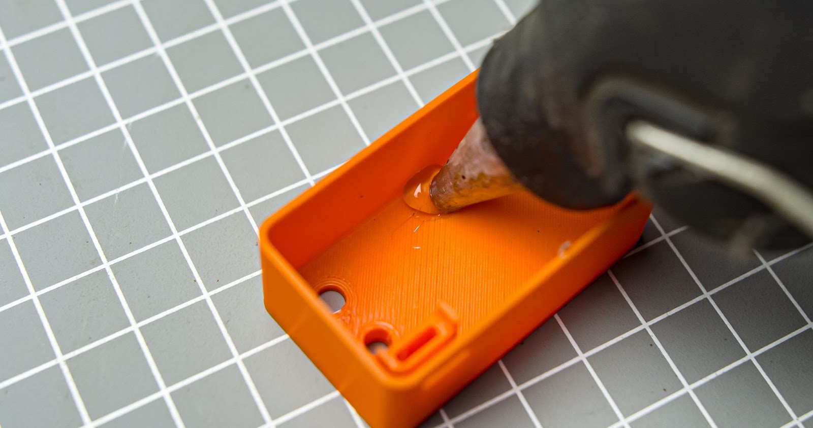
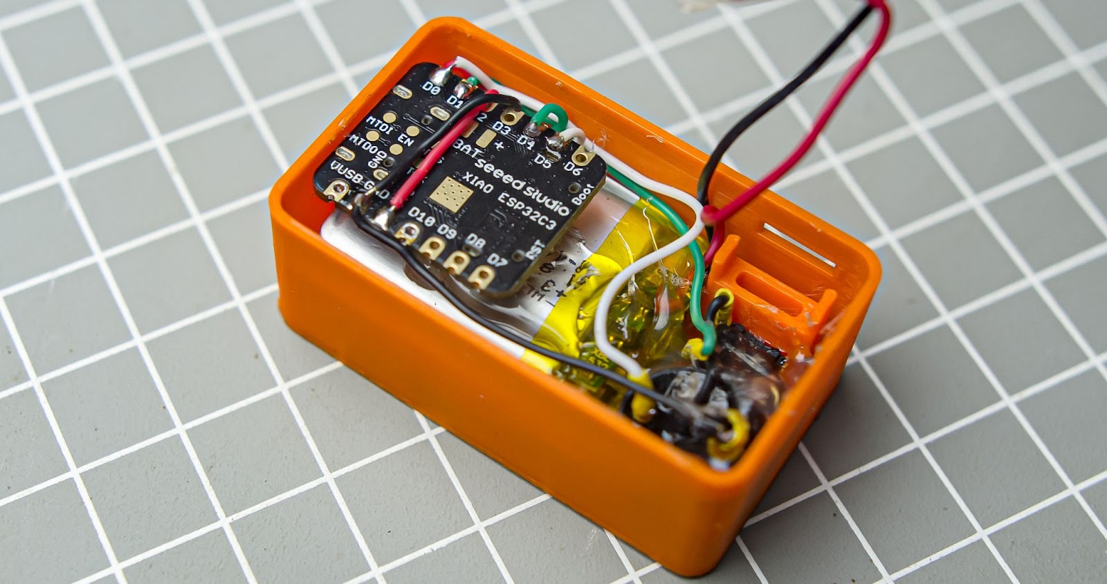
Put some glue on the main body and place the battery and IMU into it
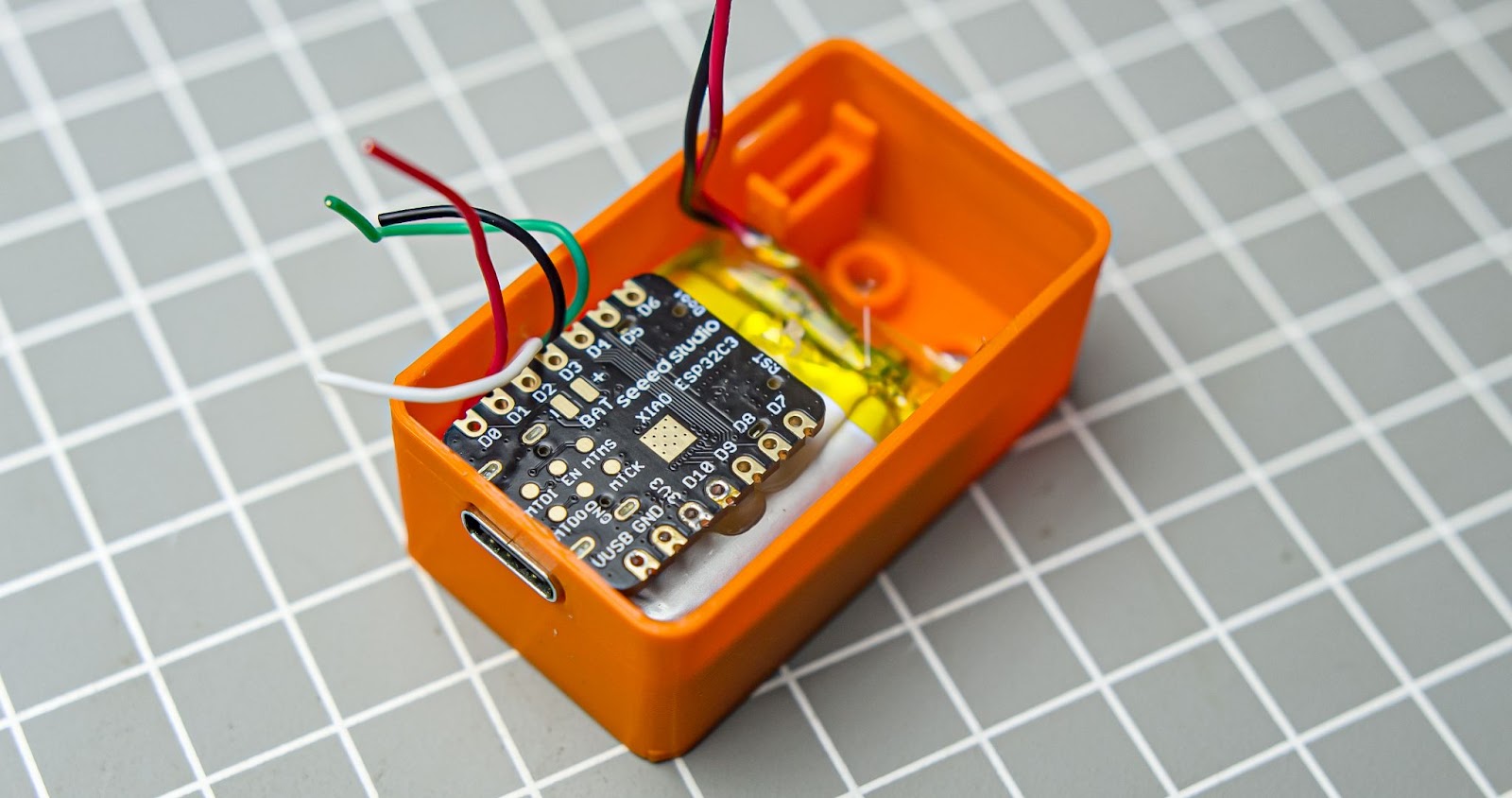
Step 4
Glur the xiao in top of the battery also along the usb c port through gap in the 3d print
Step 5
Cut and solder all 4 wire form the IMU 6050
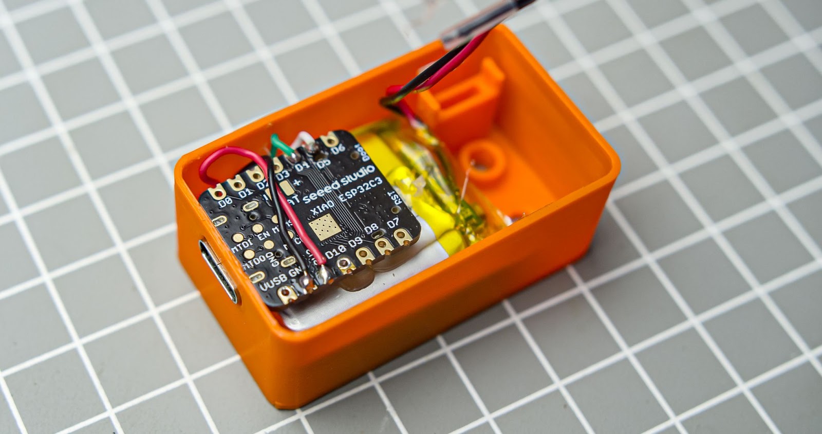
Step 6
Solder wired to the push button and buzzer , i connected button and buzzard ground in to a common ground
Step 7
Glue the push button and buzzer in to the 3d print
Step 8
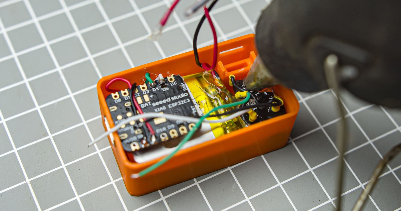
Solder the wires in to the buzzer and button and ground to the xiao
Step 9
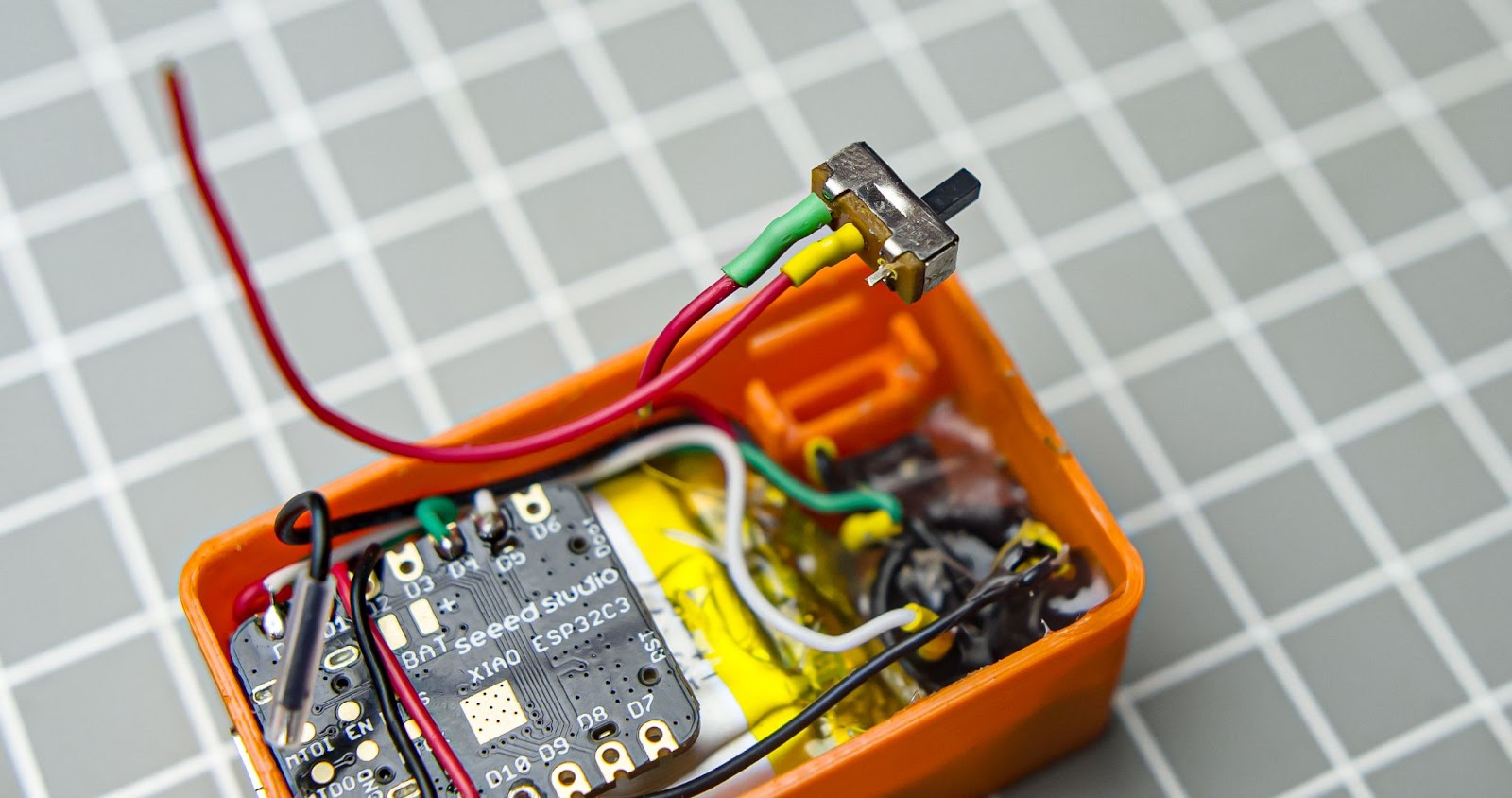
Cut the battery +ve wire and solder it to the power switch and another end of the power switch in to the +ve of battery input of xiao Connect the battery -ve wire directly in to the battery -ve input o the xiao and glue the switch

Step 10
Close the back body with cap

Test and Final Thoughts
Follow the steps given in the intro to learn the operations. you can use double-tap stick it into any surface. I used a Xiao esp32c3 for future-proof-design because without any hardwire change we can convert it to a lot of devices like notifying alarm triggers with phone notifications or performing other tasks like if you open the door it will switch on the room lights etc. I can implement this function on upcoming firmware updates for now this is all we have. thanks for checking out this project
