 JP Gleyzes
The initial board
The initial circuit was published bye "Mdog" and did exist into two versions "solo" and "4axis".
Both of these boards rely on the Ti LMD1845 H bridge circuit.
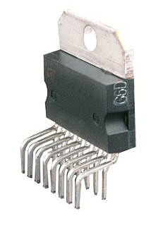
The LMD18245 is a full-bridge power amplifier with 2• DMOS Power Stage Rated at 55V and 3A
The initial boards produced by Mdog were single side PCBs. I refurbished, into this project, the "µstep solo" with dual sided PCB.
In 2009 I wrote the firmware of the boards in assembler for PIC16F57. This firmware proved to be very reliable and efficient. I publish the source code into this project today!
hardware
schematics
Here are the schematics of the µstep solo board:
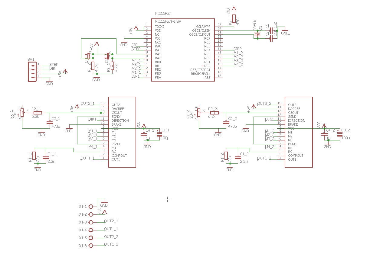
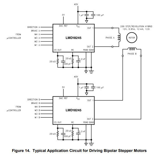
As you can see two LMD18245 are used to control, each, one motor winding. The electronics is directly copied from the datasheet.
A PIC 16F57 is used to control the LMD18245 and to interface with "external world" via classical step and dir signals.
External logic signals are TTL 5V but can work with 3.3V logic (this has proven to work with my laser cutter retrofit which is indeed using two of µstep solo boards to run controlled by an ESP32 at 3.3V).
pcb
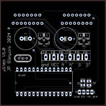
PCB was designed from Mdog's board and updated to a more compact dual sides form factor:

PCBWay kindly proposed to sponsor this project and has produced professionnal looking boards.
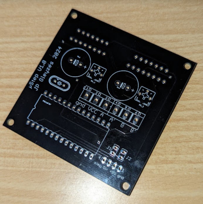
You can get this PCB on my PCBWay's shared project : https://www.pcbway.com/project/shareproject/_step_solo_Stepper_motor_control_board_3A_30b05dd2.html
Soldering is very easy. My only recommendation is to put the microcontroller on a DIL socket to be able to remove it easily to flash the firmware. (see later).
Here is the board finished: (you should note that the electrolytic capcitors are too big... but who cares !

Firmware
Original firmware was written by Mdog in C language.
The current firmware has been ported by myself from C to assembler. The reason is to get a much better control of timing which prevents "clicking noise" into the motor when high speed is required.
Here are the release notes and main specifications:
; µstep V2.0 firmware - PIC based microstepping motor controller
; copyright (C) 2009 Jean-Pierre Gleyzes <freedom2000 at free.fr>

; based on
; PICStep v2.0 Firmware - PIC based microstepping motor controller
; Copyright (C) 2004 Alan Garfield <alan@fromorbit.com>

; evolutions from PicStep's design :
; fully ported on PIC16F57 (baseline PIC : no interruptions, different pinout...)
; adapted to Mdog's µstep board design
; includes 1/2, 1/4, 1/8, 1/16 µstep mode
; includes different DAC tables for LMD18245T drivers
; includes idle mode current reduction :
    ; after 30s 75%
    ; after 90s 40%
; new in V2 possible control of current reduction mode with Mach3 "Current Hi/Low" signal
    ; when set to 1 --> forces DAC to previous full power values (no loss of step !)
    ; when 0 AND more than 10s inactivity on ALL axes : 75% power
    ; when 0 AND more than 30s inactivity on ALL axes : 40% power

; performances :
; step interrupt detection
    ; 0 to 1 edge on pin RA1
    ; time min to detect step interrupt :              6 cycles     -->      t0 =  1.2 µs (with current reduction mode)
    ; time min to detect step interrupt :              4 cycles     -->      t0 =  0.8 µs (without current reduction mode)
    ; time max to detect and process interrupt :     43 cycles     --> t0 + t1 =  8.6 µs (with current reduction mode)
    ; time max to detect and process interrupt :     32 cycles     --> t0 + t1 =  6.4 µs (without current reduction mode)
    ; timemax to detect and process time out :        63 cycles    --> t0 + t2 = 12.6 µs
    ; timemax to recover from current reduction max 43 cycles   -->      t3 =  8.6 µs (under Mach3 control "Current Hi/Low" signal set to 1

; step width MUST be greater than 1.2 µs to be detected (with current reduction mode)
; step width MUST be greater than 0.8 µs to be detected (without current reduction mode)
; step frequency MUST NOT be greater than 1/8.6 MHz = 116279 Hz in order to NOT loose steps (with current reduction mode)
; step frequency MUST NOT be greater than 1/6.4 MHz = 156250 Hz in order to NOT loose steps (without current reduction mode)
; so to be safe :
    ; use Mach3 kernel speed up to 100 kHz (maximum possible value of Mach3 in 2009 !!!)
    ; set Step Pulse width to 2 or 3 µs under Mach3

; V2.1 added self test mode : don't connect your PC // port. (compile with "self_test_mode" enabled)
; Just connect the motor and the alimentations (5V + motor) and the motor will very gently turn without step and dir signals.
This fimware was optimized to run with Mach3 but runs also perfectly well with FluidNC control or any Step/dir control board.
As you can see, step duration of >1.2µs is enough to trigger one step!
Options for compiling this fimware are simple:
Choose the table to control your motor (sinus table is the best choice if you don"t understand other choices!)
; please select only one option from the following

#define        SINUS_ENABLED        ; choose the classical Sinus table
;#define    POWER_TORQUE_ENABLED    ; choose the maximum power, maximum precision table
;#define        reverse_polarity        ; for interpCNC board (reversed polarity)
Another cool feature is to reduce motor current when no step signal is sent to the board after 30s. The position will be kept but at a lower current into thte coils. This will cooldown your motors whitout loosing steps nor position. Working current will be resumed as soon as a new step is triggered.
#define     TIMEOUT_ENABLED        ; enable power reduction after 30s timeout of inactivity

;#define        Mach3_idle_current_control ; allows control of cirrent reduction with Mach3 (signal "Current Hi/Low" on pin RC6 of Port C)

;#define        self_test_mode        ; allows to auto generate step signal to auto test the driver without PC
Comment these lines to go back to standard mode without any idle current control.
Firmware is available into my github pages. You will find there the original Mdog's source code in C. (i don't recommend using this firmware although it's easier to read than assembler!)
If you don't want to compile the assembler code then the .hex file is available here : µstep .hex file with current reduction timeout
Flashing the firmware
You will need a PICkit programmer connected like this:

You can use a breadboard and dupond wires to connect the PI16F57 to the pickit conenctor. Then use PICkit software to upload the firmware.
Your board is finished and ready to be used.